Hayward Pools Swimming Pool Pump Stratum Vrs Users Manual ( VR1000) Owners
2015-02-09
: Hayward-Pools Hayward-Pools-Hayward-Pools-Swimming-Pool-Pump-Stratum-Vrs-Users-Manual-564650 hayward-pools-hayward-pools-swimming-pool-pump-stratum-vrs-users-manual-564650 hayward-pools pdf
Open the PDF directly: View PDF ![]() .
.
Page Count: 16

PN: ISVR1000 Rev: M
USE ONLY HAYWARD GENUINE REPLACEMENT PARTS
Pomona, CA Clemmons, NC Nashville, TN
Tel: 908.351.5400 www.haywardpool.com
Model VR1000
OWNERS MANUAL
OPERATION, & PARTS
Basic safety precautions should always be followed, including the following: Failure to follow instructions can cause severe
injury and/or death.
This is the safety-alert symbol. When you see this symbol on your equipment or in this manual, look for one of the
following signal words and be alert to the potential for personal injury.
WARNING warns about hazards that could cause serious personal injury, death or major property damage and if
ignored presents a potential hazard.
CAUTION warns about hazards that will or can cause minor or moderate personal injury and/or property damage
and if ignored presents a potential hazard. It can also make consumers aware of actions that are unpredictable and unsafe.
The NOTICE label indicates special instructions that are important but not related to hazards.
THIS MANUAL CONTAINS IMPORTANT INFORMATION ON THE OPERATION,
AND SAFE USE OF THIS EQUIPMENT.
THIS MANUAL IS INTENDED FOR THE END USER OF THIS PRODUCT.
Page 2 of 16 STRATUM™ Model VR1000 P/N: ISVR1000 Rev: M
USE ONLY HAYWARD GENUINE REPLACEMENT PARTS
Pomona, CA Clemmons, NC Nashville, TN
Tel: 908.351.5400 www.haywardpool.com
IMPORTANT SAFETY INSTRUCTIONS
READ AND FOLLOW ALL INSTRUCTIONS IN THIS OWNER’S MANUAL
AND ON EQUIPMENT.
Before installing or servicing this electrical equipment, turn power supply OFF.
KEEP SAFETY LABELS IN GOOD CONDITION AND
REPLACE IF MISSING OR DAMAGED.
WARNING – To reduce risk of injury, do not permit children to use or climb on the pumps and filters. Closely supervise children at all
times. Components such as the filtration system, pumps, and heaters must be positioned to prevent children from using them as a means of access to
the pool.
CAUTION – This vacuum release system is intended for use on permanently installed swimming pools and may also be used with hot
tubs and spas. Do NOT use with storable pools. A permanently installed pool is constructed in or on the ground or in a building such that it
cannot be readily disassembled for storage. A storable pool is constructed so that it is capable of being readily disassembled for storage and
reassembled to its original integrity.
Though this product is designed for outdoor use, it is strongly recommended to protect the electrical components from the weather. Select a well-
drained area, one that will not flood when it rains. It requires free circulation of air for cooling. Do not install in a damp or non-ventilated location. If
installed within an outer enclosure or beneath the skirt of a hot tub or spa, adequate ventilation and free circulation of air must be provided to prevent
overheating of the components.
WARNING – All electrical wiring MUST be in conformance with all applicable local codes, regulations, and the
National Electrical Code (NEC). Risk of Electric Shock. Hazardous voltage can shock, burn, cause death or serious property
damage. To reduce the risk of electric shock, do NOT use an extension cord to connect unit to electric supply. Provide a
properly located outlet. All electrical wiring MUST be in conformance with applicable local and national codes and
regulations. Before working on pump or motor, turn off power supply to the pump.
WARNING – To reduce the risk of electric shock replace damaged wiring immediately. Locate conduit to prevent abuse from lawn
mowers, hedge trimmers and other equipment.
WARNING – All electrical wiring MUST be in conformance with all applicable local codes, regulations, and the National Electrical Code
(NEC) including a Ground Fault Circuit Interrupter (GFCI) in circuit. For size of GFCI required and test procedures for GFCI, see
manufacturer’s instructions. Pump MUST be permanently connected to GFCI.
WARNING – Failure to bond pump to pool structure will increase risk for electrocution and could result in injury or death. To reduce the
risk of electric shock, the electrician must comply with installation instructions and must bond the pump accordingly. In addition, the electrician
must also conform to local electrical codes for bonding requirements.
Notes to the electrician:
Use a solid copper conductor, size 8 or larger. Run a continuous wire from external bonding lug to reinforcing rod or mesh. Connect a No. 8 AWG
(8.4 mm2) solid copper bonding wire to the pressure wire connector provided on the motor housing and to all metal parts of swimming pool, spa, or
hot tub, and to all electrical equipment, metal piping (except gas piping), and conduit within 5 ft. (1.5 m) of inside walls of swimming pool, spa, or
hot tub. IMPORTANT - Reference NEC codes for all wiring standards including, but not limited to, grounding, bonding and other general wiring
procedures. NOTE - The National Electrical Code (NEC) permits use of a cord with a maximum 3 ft. (1 m) length. If your pump is equipped with a
cord complying with the NEC, the preceding four (4) hazards apply.
WARNING – Suction Entrapment Hazard.
Suction in suction outlets and/or suction outlet covers which are, damaged, broken, cracked, missing, or unsecured can cause severe injury
and/or death due to the following entrapment hazards:
Hair Entrapment- Hair can become entangled in suction outlets.
Limb Entrapment- A limb inserted into an opening of a suction outlet or suction outlet cover that is damaged, broken, cracked, missing,
or not securely attached can result in a mechanical bind or swelling of the limb.
Body Suction Entrapment- A differential pressure applied to a large portion of the body or limbs can result in an entrapment.
Evisceration/ Disembowelment - A negative pressure applied directly to the intestines through an unprotected suction outlet sump or
suction outlet cover which is damaged, broken, cracked, missing, or unsecured can result in evisceration (disembowelment).
Mechanical Entrapment- There is potential for jewelry, swimsuit, hair decorations, finger, toe or knuckle to be caught in an opening of a
suction outlet or suction outlet cover resulting in mechanical entrapment.
Page 3 of 16 STRATUM™ Model VR1000 P/N: ISVR1000 Rev: M
USE ONLY HAYWARD GENUINE REPLACEMENT PARTS
Pomona, CA Clemmons, NC Nashville, TN
Tel: 908.351.5400 www.haywardpool.com
WARNING - To reduce the risk of entrapment hazards:
o When suction outlets are less than a 18” x 23” equivalent, a minimum of two functioning suction outlets per pump
must be installed. Suction outlets in the same plane (i.e. floor or wall), must be installed a minimum of three feet
(3’) [1 meter] apart, as measured from near point to near point.
o Dual suction outlets shall be placed in such locations and distances to avoid “dual blockage” by a user.
o Dual suction fittings shall not be located on seating areas or on the backrest for such seating areas.
o The maximum system flow rate shall not exceed the flow rating of any listed (per current revision of ASME/ANSI A112.19.8) suction
outlet cover installed.
o Never use the Pool or Spa if any suction outlet component is damaged, broken, cracked, missing, or not securely attached.
o Replace damaged, broken, cracked, missing, or not securely attached suction outlet components immediately.
o In addition two or more suction outlets per pump installed in accordance with latest APSP (formally NSPI) Standards and CPSC
guidelines, follow all National, State, and Local codes applicable.
This vacuum release system is designed to prevent body suction entrapment, but not evisceration.
WARNING – Failure to remove pressure test plugs and/or plugs used in winterization of the pool/spa from the suction outlets
can result in an increase potential for suction entrapment as described above.
WARNING – Failure to keep suction outlet components clear of debris, such as leaves, dirt, hair, paper and other material
can result in an increase potential for suction entrapment as described above.
WARNING – Suction outlet components have a finite life, the cover/grate should be inspected frequently and replaced at
least every ten years or if found to be damaged, broken, cracked, missing, or not securely attached.
WARNING – All suction and discharge valves MUST be OPEN when starting the circulation system. Failure to do so could result
in severe personal injury and/or property damage. All drains and suction outlets MUST have properly installed covers, securely attached using
the screws supplied with the covers. If screws are lost, order replacement parts from your supplier.
WARNING – Hazardous Pressure. Pool and spa water circulation systems operate under hazardous pressure during
start up, normal operation, and after pump shut off. Stand clear of circulation system equipment during pump start up. Failure to
follow safety and operation instructions could result in violent separation of the pump housing and cover due to pressure in the
system, which could cause property damage, severe personal injury, or death. Before servicing pool and spa water circulation
system, all system and pump controls must be in off position and filter manual air relief valve must be in open position. Before
starting system pump, all system valves must be set in a position to allow system water to return back to the pool. Do not change
filter control valve position while system pump is running. Before starting system pump, fully open filter manual air relief valve.
Do not close filter manual air relief valve until a steady stream of water (not air or air and water) is discharged.
WARNING – Separation Hazard. Failure to follow safety and operation instructions could result in violent
separation of pump components. Strainer cover must be properly secured to pump housing with strainer cover lock ring. Before
servicing pool and spa circulation system, manual air relief valve must be in open position. Do not operate pool and spa
circulation system if a system component is not assembled properly, damaged, or missing. Do not operate pool and spa
circulation system unless filter air relief valve body is in locked position in filter upper body.
WARNING – Never operate or test the circulation system at more than 40 PSI.
WARNING – Fire and burn hazard. Motors operate at high temperatures and if they are not properly isolated from any flammable
structures or foreign debris they can cause fires, which may cause severe personal injury or death. It is also necessary to allow the motor to cool
for at least 20 minutes prior to maintenance to minimize the risk of burns.
WARNING – Failure to install according to defined instructions may result in severe personal injury or death.
DEFINITIONS:
Suction Outlet – The term Suction Outlet is a fitting, fitting assembly, cover/grate and related components that provide a means for water to exit the
pool and into the pump circulating system.
Inches of Mercury (in Hg) - A unit for measuring pressure below atmospheric (“suction” or “vacuum”) (1.0 inch Hg = .491 PSI)
Main Drain – See Suction Outlet
PSI – An abbreviation for pounds per square inch.
Page 4 of 16 STRATUM™ Model VR1000 P/N: ISVR1000 Rev: M
USE ONLY HAYWARD GENUINE REPLACEMENT PARTS
Pomona, CA Clemmons, NC Nashville, TN
Tel: 908.351.5400 www.haywardpool.com
General Information:
The VR1000 Vacuum Release System is designed as a pump controller. The system will protect pool and spa equipment from certain
mechanical failures, such as clogged drains and pipe breakage; which can cause premature pump motor failure. The system monitors
and recognizes a change in pressure and electrical power. When a change occurs, it will shut down the pump, and vent the suction
line. Automatic soft start should provide notice to swimmers or bathers on pump startup. The VR1000 meets the requirements of
ASTM Specification F2387-04. Meets ASME Standard 112.19.17. Meets UL Std 1563 as well as certified to Can/CSA Std. C27.2
No. 218.1.
The VR1000 system will automatically restart in most instances. Should a manual restart be required, pressing the “OK” button will
restart the system. “Unprotected Mode” Mode can be entered, after restart, by holding “NO” & “OK” buttons. “Unprotected
Mode” mode lasts 30 minutes, providing NO protection for swimmers or bathers. DO NOT ALLOW SWIMMERS OR
BATHERS IN THE POOL OR SPA WHEN THE SYSTEM IS IN “UNPROTECTED” MODE.
For proper installation and to avoid unnecessary service calls, read this manual carefully and completely.
WARNING – This product should be installed and serviced only by a qualified professional. Failure to install and/or
operate according to defined instructions and/or use of non-Hayward replacement parts will void the warranty.
CAUTION – All electrical wiring MUST be in conformance with all applicable local codes, regulations, and the National
Electrical Code (NEC).
Introduction:
This manual contains information for the proper operation of the Hayward VR1000 Vacuum Release System. The
instructions in this manual MUST be followed precisely.
NOTICE – The VR1000 is rated for 115 VAC 50/60Hz for up to a 1 horsepower pump motor or 208/230 VAC
50/60Hz for up to a 3 horsepower pump motor.
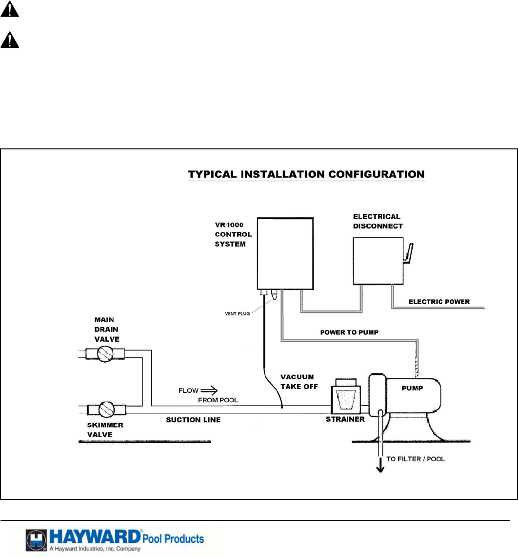
FIG 1
Page 5 of 16 STRATUM™ Model VR1000 P/N: ISVR1000 Rev: M
USE ONLY HAYWARD GENUINE REPLACEMENT PARTS
Pomona, CA Clemmons, NC Nashville, TN
Tel: 908.351.5400 www.haywardpool.com
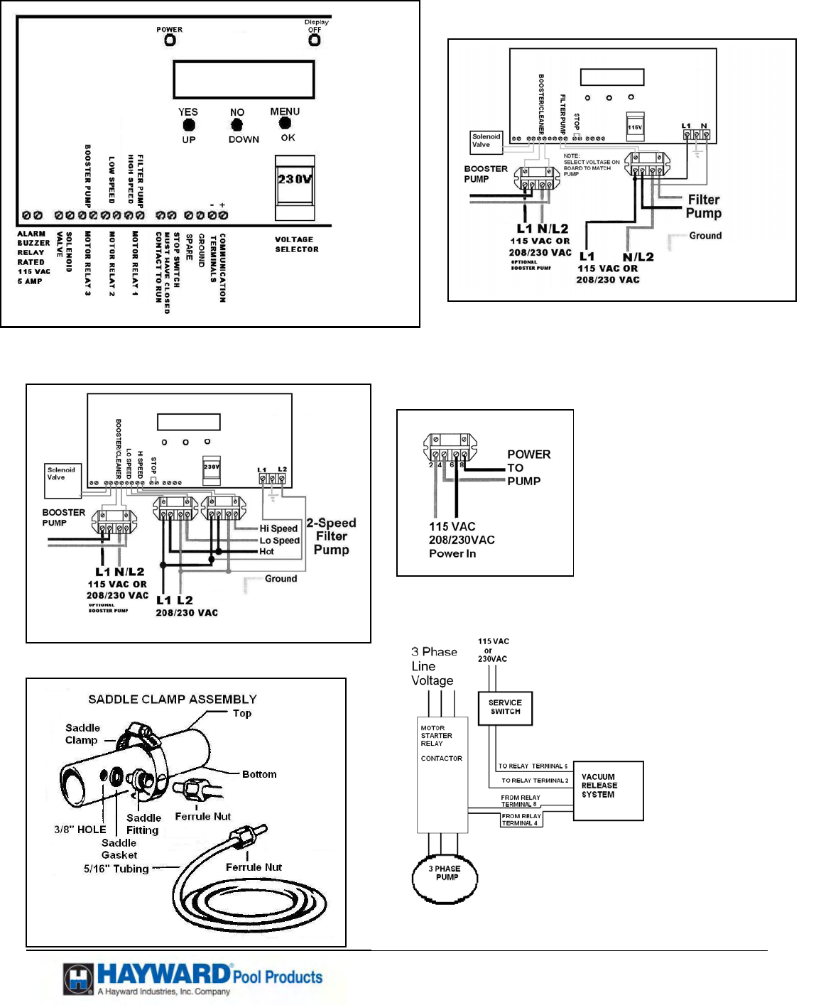
FIG 3
Internal Control
External
FIG 2
FIG 4
Internal
Control
FIG 5
FIG 7
THREE PHASE PUMP MOTOR
SUGGESTED CONNECTION
FIG 6
Page 6 of 16 STRATUM™ Model VR1000 P/N: ISVR1000 Rev: M
USE ONLY HAYWARD GENUINE REPLACEMENT PARTS
Pomona, CA Clemmons, NC Nashville, TN
Tel: 908.351.5400 www.haywardpool.com
HAYWARD POOL
PRODUCTS
02-02-07
12:00 P.M.
SET TIME AND
DATE? Y/N
SELECT POOL
TECH. MODE? Y/N
HAYWARD VR1000
CALIBRATING
VR1000 VER X.X
STARTING PUMP
VR1000 VER X.X
STABILIZING
VR1000 VER X.X
MONITORING
VR1000 VER X.X
STOP SWITCH
CUSTOMER SCREENS ON VR1000
No Action Required
No Action Required
No Action Required. However, setting the time and date can be done at this time.
(If the date and time is not maintained from the last time it was set, the battery
needs to be replaced.) If “YES” follow screen instructions
SET TIMER EVENTS is the only used when the VR1000 has been set to allow
control of pump on/off times.(or with use of a 2-speed pump) See Page 8 for screen
information.
No Action Required. Defaults to “CUSTOMER Mode” in 5 seconds.
See Technician Manual for options.
The following screens are shown for information only:
CUSTOMER SCREENS showing errors and exceptions:
The system will not start if the optional “STOP Switch” is pressed in.
Action Required: Reset “STOP Switch”
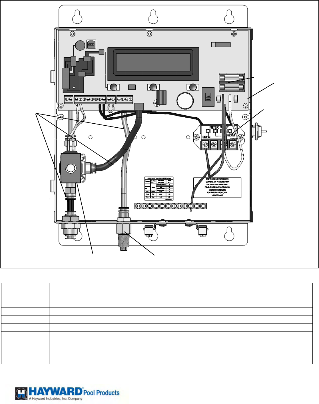
Sensor/Solenoid Venting Error. Remove and clean or replace the vent plug.
(This is the cone shaped device on the exterior/bottom of the box.) (See Fig 1) If
vent cleaning/replacement does not correct the problem, replace the solenoid
valve (See Fig 7). If neither option corrects the problem, replace the unit.
“No Stabilization" indicates that there is likely a problem with the pump. The
pump basket should be checked for debris. Other pumping issues can cause
stabilization problems.
Self Test Indicates the system is checking itself for proper operation of its
components. The pump may cycle and restart. No action is required.
VR1000 VER X.X
S/S VENT ERROR
VR1000 VER X.X
N
O STABILIZATION
VR1000 VER X.X
SELF TEST
SET TIMER
EVENTS Y/N
Page 7 of 16 STRATUM™ Model VR1000 P/N: ISVR1000 Rev: M
USE ONLY HAYWARD GENUINE REPLACEMENT PARTS
Pomona, CA Clemmons, NC Nashville, TN
Tel: 908.351.5400 www.haywardpool.com
SET TIME AND
DATE? Y/N
Over Window Vacuum indicates a vacuum level detected that is above normal for
the pool system. The system should restart.
Under Vacuum Window indicates a problem with the inlet water flow to the
pump. Low volume flow can be caused by line breaks, or low water levels. The
system should restart.
High Vacuum Alert indicates the system has stopped the pump, vented, and set
off the alarm.
CUSTOMER ACTION IS REQUIRED. Clear the cause of the problem. Then
press the “OK” button to restart the system.
System Won't Stabilize indicates the system has stopped the pump three times and
set off the alarm.
CUSTOM ACTION IS REQUIRED. Clear the cause of the problem. Then
press the “OK” button to restart the system.
Too Many Sen/Sol Errs Or No Prime indicates the system has vented and stopped
the pump three times and set off the alarm.
CUSTOM ACTION IS REQUIRED. Clear the cause of the problem. Then
press the “OK” button to restart the system.
• If the VR1000 has shut the pump down due to “HIGH VACUUM” and does not restart, due to debris in
the suction line, the line must be cleared. This is normally done through the use of a garden hose or other
method.
• If the green light is on, and the Red light is on with the Pump not running during a normal operational time
cycle, it is suggested that cutting the power to the system and then restoring the power will reset the system.
(This will assure the system program is operating.)
• The green light indicates power is on.
• The combination of a green light on and a yellow light on indicates that the system is monitoring the pool,
but the screen has been turned off due to a high temperature internally in the box.
CUSTOMER ACCESSIBLE MODES
To initiate a self-test through the use of the push buttons on the display push button “OK/MENU” and
release. This only causes the system test in “RUN MODE”. The self test is run by the customer just to
confirm the VR1000 is actively protecting the pool/spa. The system should restart and stabilize.
Set the time of day clock. In normal operation the time of day will be displayed on
the LCD.
When the board is first powered up the time and date are displayed. Pushing the
“Menu” button will step through the date and time of day set up.
Pushing the “NO” will go to next step. (5 Seconds of inactivity will go to next step.)
“YES” follow screen instructions.
NOTE: If system does not maintain date and time when the power fails or is disconnected, replace the
battery.
VR1000 OVER
WINDOW VACUUM
VR1000 UNDER
WINDOW VACUUM
HIGH VACUUM
ALERT
SYSTEM WON'T
STABILIZE
TOO MANY SEN/SOL
ERRS OR NO PRIME
Page 8 of 16 STRATUM™ Model VR1000 P/N: ISVR1000 Rev: M
USE ONLY HAYWARD GENUINE REPLACEMENT PARTS
Pomona, CA Clemmons, NC Nashville, TN
Tel: 908.351.5400 www.haywardpool.com
The timer events are used to control the ON and OFF times of the Filter Pump,
Booster Pump and Low Speed on a two speed Pump. Dip switch #4 Must be on to
allow the timers to be set. A “YES” will allow the following timer settings.
“YES” 7-day all the week long the pumps will run at the same times.
“NO” Each days timers must be set
The 7-day time clock has two (2) on/off programs per day, while each day only has
one program. All time clocks are selected either as “7-day” or “each day”. If “each day” is selected,
you will need to program “ON” times for every day and “OFF” times for every day, even if you
want them all to be the same. All times are adjusted in 1 minute increments.). If you program the
“ON” time equal to the “OFF” time (“12:01 AM to 11:59 PM”) the output will always be “ON”.
For the Booster pump timer “ON” time equals “OFF” time the pump will always be “OFF”
7 DAY MODE
“YES” will use the timing events currently stored in the VR1000
“NO” will allow setting the timers
Blinking time indicates that the timer is ready to be set.
“Down” will move On time earlier
“UP” will move On time later. Menu/OK to go to next screen.
Blinking time indicates that the timer is ready to be set.
“Down” will move On time earlier
“UP” will move On time later. Menu/OK to go to next screen.
Blinking time indicates that the timer is ready to be set.
“Down” will move On time earlier
“UP” will move On time later. Menu/OK to go to next screen.
Blinking time indicates that the timer is ready to be set.
“Down” will move On time earlier
“UP” will move On time later. Menu/OK to go to next screen.
Low Speed On will only appear if dip switch 3 is “ON”
This will allow setting the timing on the Low speed of a two speed pump.
A “N” will allow setting the On and Off time.
Follow the above instructions for the timer settings.
BST On is the timer for the Booster Pump. To set timer follow the above.
Repeat the above for the second timer cycle. For “OVERNIGHT” operation, set
the first timer cycle starting at midnight (12:01 AM) as the desired “ON” time
and then the desired AM “OFF” time. The second timer cycle should be set
from the desired PM “ON” time to midnight (11:59 PM) as the “OFF” time.
EACH DAY MODE
Note when each day mode is selected the timers must be set on a daily basis.
The week days will be stepped through to allow individual day setting.
Y= 7 DAY MODE
N
= EACH DAY MODE
ON = 04:00 AM
OFF=08:00 PM OK?
SET TIMER
EVENTS? Y/N
Low Speed On=
08:00 AM OK?
Daily On Hour =
4 AM
Daily On Min=
1
Daily Off Hour =
6 AM
Daily Off Min =
0
BST On=04:00PM
Off = 0400 PM OK?
On=0700AM Mon
Off= 0400PM OK?
Tue. = Mon
OK? Y/N

Page 9 of 16 STRATUM™ Model VR1000 P/N: ISVR1000 Rev: M
USE ONLY HAYWARD GENUINE REPLACEMENT PARTS
Pomona, CA Clemmons, NC Nashville, TN
Tel: 908.351.5400 www.haywardpool.com
OPERATIONS
Normal operational mode monitors pool conditions for proper operation.
The system operates in four basic states during normal pool monitoring.
STARTUP – PULSING
The vacuum solenoid valve is opened and closed several times to ‘soft start’ the system at startup time to warn
swimmers that the pump is running. A self-test then occurs to verify that the sensor / solenoid subsystem is
functioning properly. During this time a High Vacuum setting provides protection. As the pump starts priming
the system is providing protection for swimmers. STABILIZING is entered if the system experiences no errors.
With the pump off the system will take an initial voltage reading. This reading will be stored to allow low
voltage cut off of the pump. In no case will the low voltage be allowed to drop below 188VAC or 100VAC
(factory calibrated) depending on initial reading. The low voltage will turn the pump off until normal voltage is
restored.
STABILIZING
The pump is running and the vacuum sensor is monitoring the pool pump inlet vacuum. The High Vacuum
setting continues to provide protection. The pump will become fully primed and the vacuum should stabilize.
The operating vacuum will then be determined. Detection of vacuum being out of window from the calibrated
value or any other errors will result in entering the Vacuum Anomaly Detected state. The following state is
entered if the system operates properly.
MONITORING
Monitoring is when the pump is running and a stable vacuum has been established. Vacuum measurements are
taken at about 1000 samples per second, yielding a filtered vacuum value about every hundredth of a second.
The filtered vacuum values are compared to the established normal vacuum value. When this filtered vacuum
value is outside an established window Vacuum Anomaly Detected state is entered.
Continuous operation in Monitoring is periodically interrupted by a “self-test” where a change in vacuum must
be detected. If any problem is detected during “self-test,” the Vacuum Anomaly Detected state is entered.
Green light will display with power to the system. (If both the Yellow and Green light are on, the system has
turned off the display due to high temperatures internally in the box. The system is still in the operation.)
VACUUM ANOMALY DETECTED
The pump(s) and the vacuum solenoid valve are turned off within 0.1 seconds to help reduce the risk of certain
types of entrapment. The system may also reduce equipment damage due to a cracked pipe or low pool water
levels. Startup with Pulsing state will be entered after a short delay and the stabilization process is repeated
allowing the system to adapt to changing pool conditions, such as gradual obstruction of the filter. Three
occurrences of certain errors will cause the system to shut down the pump(s), sound the alarm(s) and update the
LCD display to indicate the reason. The audible alarm(s) may be silenced through following instructions on the
display or through the remote “stop” switch(s); or else the audible alarm(s) will be silenced automatically after
10 minutes. However manual intervention, including responding to certain questions via the LCD display and
function pushbuttons, is required in order to restart the system.
Page 10 of 16 STRATUM™ Model VR1000 P/N: ISVR1000 Rev: M
USE ONLY HAYWARD GENUINE REPLACEMENT PARTS
Pomona, CA Clemmons, NC Nashville, TN
Tel: 908.351.5400 www.haywardpool.com
SPARE PARTS
Item Part Number Description Qty
1 VRX100E Solenoid Valve 24 VAC 1.0
2 GLX-RELAY Contactor/Relay OMRON G7L-2A-BUB-JCB (24DC) 1.0
3 VRX100KIT2 Fitting Kit with saddle fitting (See Fig 6) 1.0
4 VRX100H 250ma Fuse 1.0
5 VRX100PAK Tubing Replacement Kit 1.0
6 VRX100F Vent Filter ¼” NPTM (Pack includes 8’ hose & fittings
to extend hose above water level)
1.0
7 CLX220J25 5/16” Tubing x 25’ Long (See Fig 6) 1.0
8 VRXPCBA Printed Circuit Board 1.0
1
2
4
5
6 FIG 8
8
Page 11 of 16 STRATUM™ Model VR1000 P/N: ISVR1000 Rev: M
USE ONLY HAYWARD GENUINE REPLACEMENT PARTS
Pomona, CA Clemmons, NC Nashville, TN
Tel: 908.351.5400 www.haywardpool.com
WARNING – Hazardous Pressure. Pumps, filters, and other equipment components of a swimming pool
filtration systems operate under pressure. Incorrectly installed and/or improperly tested filtration equipment and/or components
may fail resulting in injury and/or property damage.
Plumbing
Use Teflon tape to seal threaded connections on molded plastic components. All plastic fittings must be new or thoroughly cleaned before
use. NOTE: Do NOT use Plumber’s Pipe Dope as it may cause cracking of the plastic components.
When applying Teflon tape to plastic threads, wrap the entire threaded portion of the male fitting with one to two layers of tape. Wind the
tape clockwise as you face the open end of the fitting, beginning at the end of the fitting.
The pump suction and outlet ports have molded-in thread stops. Do NOT attempt to force hose connector fitting past this stop. It is
only necessary to tighten fittings enough to prevent leakage. Tighten fitting by hand and then use a tool to engage fitting an additional 1 ½
turns. Use care when using Teflon tape as friction is reduced considerably; do NOT over-tighten fitting or you may cause damage. If
leaks occur, remove connector, clean off old Teflon tape, re-wrap with one to two additional layers of Teflon tape, and re-install connector.
Fittings
Fittings restrict flow. For better efficiency, use the fewest possible fittings (but at least two suction outlets). Avoid fittings that could cause
an air trap. Pool and spa fittings MUST conform to the International Association of Plumbing and Mechanical Officials (IAPMO)
standards.
Electrical
WARNING – Ground motor before connecting to electrical power supply. Failure to ground pump motor
can cause serious or fatal electrical shock hazard.
WARNING – Do NOT ground to a gas supply line.
WARNING – TO AVOID DANGEROUS OR FATAL ELECTRICAL SHOCK, TURN OFF POWER
TO MOTOR BEFORE WORKING ON ELECTRICAL CONNECTIONS.
WARNING – Ground Fault Circuit Interrupter (GFCI) tripping indicates electrical problem. If GFCI trips
and won’t reset, consult electrician to inspect and repair electrical system.
WARNING – Fire Hazard. Match supply voltage to motor nameplate voltage.
Insure that the electrical supply available agrees with the motor’s voltage, phase, and cycle, and that the wire size is
adequate for the H.P. (KW) rating and distance from the power source. NOTE: All electrical wiring MUST be in
conformance with all applicable local codes, regulations, and the National Electrical Code (NEC).
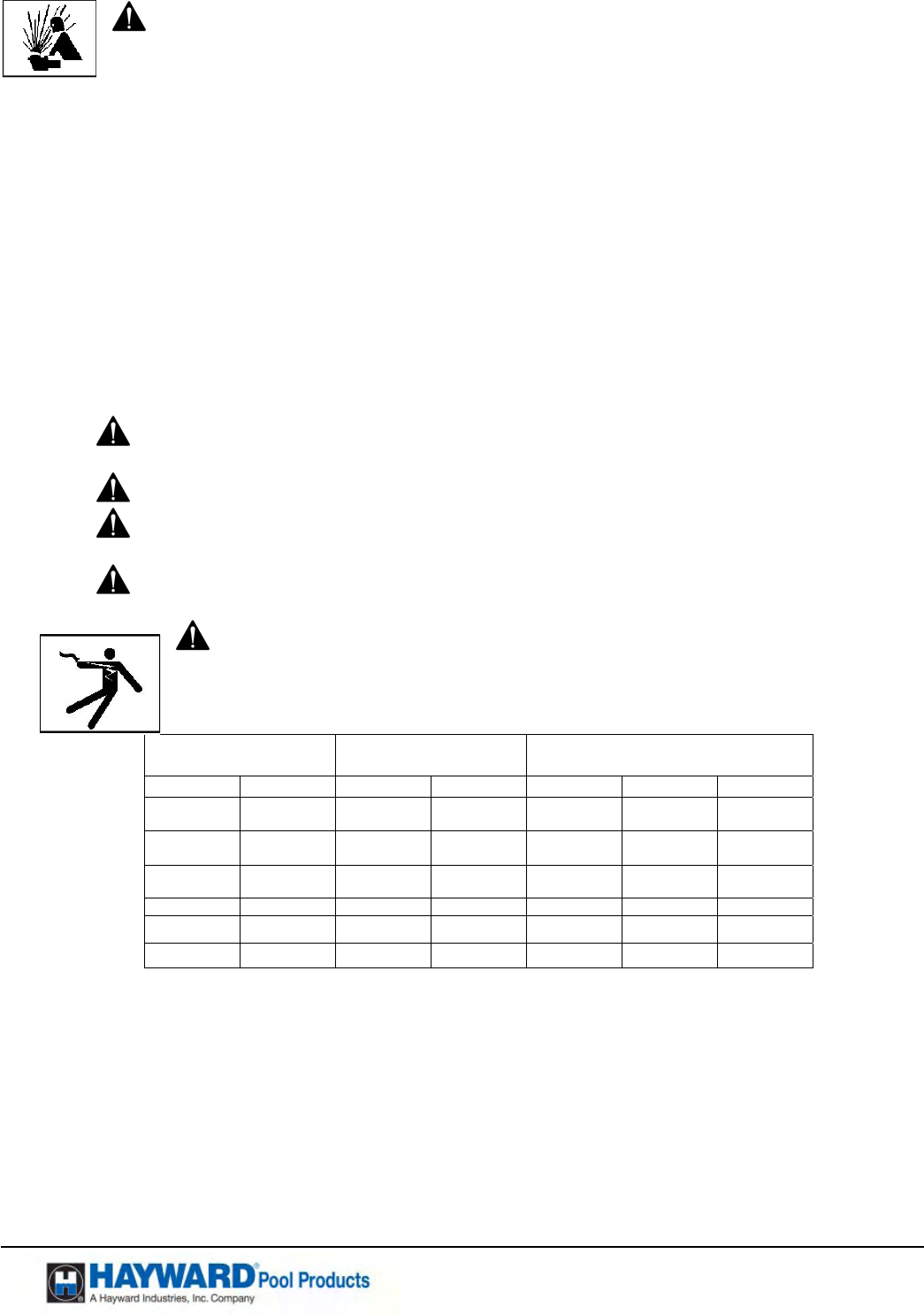
Brake Horsepower
BHP
Full Rate Horsepower
(FRHP) Motor Electric V/A
HP KW HP KW Voltage Amps Wire Size
.99 .74 .50 0.37
208-230
115
5.3-4.9
9.8
14 AWG
14 AWG
1.39 1.04 .75 0.56
208-230
115
6.0-5.5
11.0
14 AWG
14 AWG
1.85 1.39 1.00 0.75
208-230
115
8.5-7.8
15.6
14 AWG
12 AWG
2.40 1.80 1.50 1.12 208-230 11-10.2 14 AWG
2.70 2.02 2.00 1.50 208-230 13.0-11.8 12 AWG
3.60 2.69 3.00 2.25 208-230 16.0-15.8 12 AWG
Voltage at motor MUST NOT be more than 10% above or below motor name plate rated voltage, or motor may overheat, causing overload
tripping and reduced component life. If voltage is less than 90% or more than 110% of rated voltage when motor is running at full load,
consult power company.
Grounding/Bonding
Install, ground, bond, and wire motor in accordance with local and national electrical code requirements.
Permanently ground motor. Use green ground terminal provided under motor canopy or access place; use size and type wire required by
code. Connect motor ground terminal to electrical service ground.
Reference NEC codes for all wiring standards including, but not limited to, grounding, bonding and general wiring procedures.
Use a solid copper conductor, size 8 or larger. Run wire from external bonding lug to reinforcing rod or mesh. Connect a No. 8 AWG (8.4
mm2) solid copper bonding wire to the pressure wire connector provided on the motor housing and to all metal parts of swimming pool,
spa, or hot tub, and to all electrical equipment, metal piping (except gas piping), and conduit within 5 ft. (1.5 m) of inside walls of
swimming pool, spa, or hot tub.
Page 12 of 16 STRATUM™ Model VR1000 P/N: ISVR1000 Rev: M
USE ONLY HAYWARD GENUINE REPLACEMENT PARTS
Pomona, CA Clemmons, NC Nashville, TN
Tel: 908.351.5400 www.haywardpool.com
Wiring
WARNING – All electrical wiring MUST be in conformance with all applicable local codes, regulations, and the National
Electrical Code (NEC).
Pump MUST be permanently connected to circuit. If other lights or appliances are also on the same circuit, be sure to add their amp loads
before figuring wire and circuit breaker sizes. Use the load circuit breaker as the Master On-Off switch.
Install a Ground Fault Circuit Interrupter (GFCI) in circuit; it will sense a short-circuit to ground and disconnect power before it becomes
dangerous to pool users. For size of GFCI required and test procedures for GFCI, see manufacturer’s instructions. In case of a power
outage, check GFCI for tripping, which will prevent normal pump operation. Reset if necessary.
NOTE: If you do not use conduit when wiring motor, be sure to seal wire opening on end of motor to prevent dirt, bugs, etc., from
entering.
Start-Up & Operation
Prior to Start-Up
Notice: If it is necessary to perform a pressure test prior to initial use to ensure pump is functioning properly. The following criteria should
be maintained for this test:
1. Ensure all pump and system components are sealed properly to prevent leaks.
2. Remove any trapped air in the system by fully opening filter manual air relief valve until a steady stream of
water is discharged.
3. Allow no more than 40 psi (172 kPa) at a water temperature no higher than 100° F (38° C).
4. Run pressure test for no longer than 24 hours. Immediately inspect all parts to verify they are intact and
functioning properly.
5. Have a professional perform this test.
Fill strainer housing with water to suction pipe level. NEVER OPERATE THE PUMP WITHOUT WATER. Water acts as a coolant
and lubricant for the mechanical shaft seal.
ATTENTION – NEVER run pump dry. Running pump dry may damage seals, causing leakage, flooding, and voids
warranty. Fill strainer housing with water before starting motor.
ATTENTION – Do NOT add chemicals to pool/spa system directly in front of pump suction. Adding undiluted
chemicals may damage pump and voids warranty.
ATTENTION – Before removing strainer cover:
1. STOP PUMP before proceeding.
2. CLOSE VALVES in suction and outlet pipes.
3. RELEASE ALL PRESSURE from pump and piping system using filter manual air relief valve. See filter owner’s
manual for more detail.
WARNING – If pump is being pressure tested (40 PSI MAXIMUM), be sure pressure has been released before removing
strainer cover.
Priming Pump
CAUTION – All suction and discharge valves MUST be OPEN, as well as filter air relief valve (if available) on filter,
when starting the circulating pump system. Failure to do so could result in severe personal injury.
Release all pressure from filter, pump, and piping system. See filter owner’s manual.
If water source is higher than the pump, pump will prime itself when suction and outlet valves are opened. If water source is
lower than the pump, unscrew and remove strainer cover; fill strainer housing with water.
Clean and lubricate strainer cover O-ring with "Jack's 327" each time it is removed. Inspect O-ring and re-install on strainer
cover.
Replace strainer cover on strainer housing; turn clockwise to tighten cover.
NOTE: Tighten strainer cover by hand only (no wrenches).
Turn on power and wait for pump to prime, which may take up to five (5) minutes. Priming time will depend on vertical length of suction
lift and horizontal length of suction pipe. If pump does NOT prime within five minutes, stop motor and determine cause. Be sure all
suction and discharge valves are open when pump is running. See Pump Owners Manual For Troubleshooting Guide.
ATTENTION – Wait five (5) seconds before re-starting pump. Failure to do so may cause reverse rotation of motor and
consequent serious pump damage.
Close air relief valve after pump is primed.
Page 13 of 16 STRATUM™ Model VR1000 P/N: ISVR1000 Rev: M
USE ONLY HAYWARD GENUINE REPLACEMENT PARTS
Pomona, CA Clemmons, NC Nashville, TN
Tel: 908.351.5400 www.haywardpool.com
Maintenance
Clean strainer basket regularly. Do NOT strike basket to clean. Inspect strainer cover gasket regularly and replace as
necessary.
Keep motor clean. Insure air vents are free from obstruction to avoid damage. Do NOT use water to hose off motor.
Storage/Winterization
WARNING – Separation Hazard. Do not purge the system with compressed air. Purging the
system with compressed air can cause components to explode, with risk of severe injury or death to anyone
nearby. Use only a low pressure (below 5 PSI), high volume blower when air purging the pump, filter, or piping.
ATTENTION – Do NOT use anti-freeze solutions (except propylene glycol) in your pool/spa
system. Propylene glycol is non-toxic and will not damage plastic system components; other anti-freezes are highly
toxic and may damage plastic components in the system.
Drain all water from pump and piping when expecting freezing temperatures or when storing pump for a long time (see
instructions below). Gravity drain system as far as possible. Disconnect hose from VR1000 electrical box.
Keep motor dry and covered during storage. To avoid condensation/corrosion problems, do NOT cover or wrap pump with
plastic film or bags.
Storing Pump For Winterization
WARNING – To avoid dangerous or fatal electrical shock hazard, turn OFF power to motor before
draining pump. Failure to disconnect power may result in serious personal injury or death.
1. Drain water level below all inlets to the pool.
2. Remove drain plugs from bottom of strainer body, and remove strainer cover from strainer housing.
3. Disconnect pump from mounting pad, wiring system (after power has been turned OFF), and piping
system.
4. Once the pump is removed of water, re-install the strainer cover and drain plugs. Store pump in a dry area.
• After all the settings have been completed, a test consisting of three simulated entrapments must
be conducted to verify proper installation, calibration and operation.
• An entrapment can be simulated by partially closing or repositioning a valve so that there will be a
change in the flow pattern. That is, changing the pattern of flow from the suction outlet (Main Drain)
to the skimmer will simulate an entrapment.
• Periodic testing of the VR1000 can be performed by pushing the “OK” button. This will verify
proper installation and operation.
WARNING - Body Suction Entrapment Hazard
Suction in suction outlets can cause severe injury and/or death due to a differential pressure
applied to a large portion of the body or limbs. STRATUM™ “Unprotected” Mode: Is when the
p
ump is operating and the STRATUM™ is NOT providing any protection against Body Suction
Entrapment. Do not be allow Swimmers and Bathers in the pool and spa when the STRATUM™
is in “Unprotected” mode. The STRATUM™ only provides a layer of protection against Body
Suction Entrapment in monitoring mode.
NOTICE: The VR1000 will beep to indicate the unit is in unprotected mode.

Page 14 of 16 STRATUM™ Model VR1000 P/N: ISVR1000 Rev: M
USE ONLY HAYWARD GENUINE REPLACEMENT PARTS
Pomona, CA Clemmons, NC Nashville, TN
Tel: 908.351.5400 www.haywardpool.com
HAYWARD® LIMITED WARRANTY
This equipment was inspected before shipment from our plant. To original purchasers of this equipment, Hayward
Pool Products, 620 Division Street, Elizabeth, New Jersey, warrants its products free from defects in materials and
workmanship for a period of ONE (1) year from the date of purchase.
Parts which fail or become defective during the warranty period, except as a result of freezing, negligence, improper
installation, use, or care, shall be repaired or replaced, at our option, without charge, within 90 days of the receipt of
defective product, barring unforeseen delays.
To obtain warranty replacements or repair, defective components or parts should be returned, transportation paid, to
the place of purchase, or to the nearest authorized Hayward service center. For further Hayward dealer or service
center information, contact Hayward customer service department. No returns may be made directly to the factory
without the express written authorization of Hayward Pool Products
To original purchasers of this equipment, Hayward Pool Products warrants its vacuum release systems to be free
from defects in materials and workmanship for a period of ONE (1) year from the date of purchase.
Vacuum Release Systems which become defective during the warranty period, except as a result of freezing,
negligence, improper installation, use or care, shall be repaired or replaced, at our option, without charge.
All other conditions and terms of the standard warranty apply.
Hayward shall not be responsible for cartage; removal and/or reinstallation labor or any other such costs incurred in
obtaining warranty replacements.
The Hayward Pool Products warranty does not apply to components manufactured by others. For such products, the
warranty established by the respective manufacturer will apply.
Some states do not allow a limitation on how long an implied warranty lasts, or the exclusion or limitation of
incidental or consequential damages, so the above limitation or exclusion may not apply to you.
This warranty gives you specific legal rights, and you may also have other rights, which vary from state to state.
Hayward Pool Products
620 Division Street
*Supersedes all previous publications. Elizabeth, NJ 07207
Page 15 of 16 STRATUM™ Model VR1000 P/N: ISVR1000 Rev: M
USE ONLY HAYWARD GENUINE REPLACEMENT PARTS
Pomona, CA Clemmons, NC Nashville, TN
Tel: 908.351.5400 www.haywardpool.com
© Hayward Pool Products 2007
All rights reserved.
▲Retain this Warranty Certificate (upper portion) in a safe and convenient location for your records.
DETACH HERE: Fill out completely and mail within 10 days of purchase/installation, or REGISTER ONLINE AT WWW.HAYWARDNET.COM
---------------------------------------------------------------------------------------------------------
Mail to: Hayward Pool Products, 620 Division Street, Elizabeth, NJ 07207, Attn: Warranty Dept.
Please Print Clearly: Warranty Registration Card
Name__________________________________________________ Purchased Date:________________________________________________
Address________________________________________________ Purchased from:
City______________________ State_________ Zip____________ Company name________________________________________________
E-mail Address__________________________________________ Address_______________________________________________________
Phone No:______________________________________________ City__________________________ State_________ Zip_______________
Product Model Number _______VR1000_______________ Please send me more information on these other
products from Hayward:
Product Serial No. _____________________________________ □ Pump □ Filter □ Automatic Pool Cleaner □ Light
□ New Installation □ Replacement □ Chlorinator □ Skimmer □ Heater □ Heat Pump
Type of In-Ground Pool: □ Salt/Chlorine Generator □ Controls
□ Vinyl □ Fiberglass □ Gunite May we contact you for future product promotions and offerings? □ Yes □ No
Size of Pool______________________________________
© Hayward Pool Products 2007 REGISTER YOUR WARRANTY ON-LINE AT WWW.HAYWARDNET.COM
All rights reserved.
PRODUCT REGISTRATION
(Retain For Your Records)
DATE OF INSTALLATION ____________________
INITIAL PRESSURE GAUGE READING (CLEAN FILTER) _______________________
PUMP MODEL ________________ HORSEPOWER _______________________
FILTER MODEL ________________ SERIAL NUMBER _______________________
MODEL VR1000 SERIAL NUMBER _______________________

Page 16 of 16 STRATUM™ Model VR1000 P/N: ISVR1000 Rev: M
USE ONLY HAYWARD GENUINE REPLACEMENT PARTS
Pomona, CA Clemmons, NC Nashville, TN
Tel: 908.351.5400 www.haywardpool.com
THIS PAGE IS BLANK
