Healthrider Hrtl195090 Owners Manual NTL10850 214878
HEALTHRIDER-Treadmill-Club-Series_H155T
2014-07-19
: Healthrider Healthrider-Hrtl195090-Owners-Manual healthrider-hrtl195090-owners-manual healthrider pdf
Open the PDF directly: View PDF ![]() .
.
Page Count: 40
USER'S MANUAL
CAUTION
Read all precautions and instruc-
tions in this manual before using
this equipment. Save this manual
for future reference.
Serial
Number
Decal
Model No. HRTL19509.0
Serial No.
Write the serial number in the space
above for reference.
QUESTIONS?
If you have questions, or if parts are
damaged or missing, DO NOT
CONTACT THE STORE; please
contact Customer Care.
IMPORTANT: Please register this
product (see the limited warranty
on the back cover of this manual)
before contacting Customer Care.
CALL TOLL-FREE:
1-888-922-4222
Mon.–Fri. 6 a.m.–6 p.m. MT
Sat. 8 a.m.–4 p.m. MT
ON THE WEB:
www.healthriderservice.com
www.healthrider.com
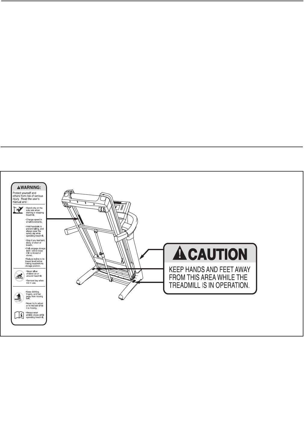
TABLE OF CONTENTS
WARNINGDECALPLACEMENT ..............................................................2
IMPORTANTPRECAUTIONS .................................................................3
BEFOREYOUBEGIN .......................................................................6
ASSEMBLY ...............................................................................7
OPERATIONANDADJUSTMENT ............................................................14
HOWTOFOLDANDMOVETHETREADMILL ..................................................26
TROUBLESHOOTING ......................................................................28
EXERCISEGUIDELINES ...................................................................32
PARTLIST ...............................................................................33
EXPLODEDDRAWING .....................................................................35
ORDERINGREPLACEMENTPARTS ..................................................BackCover
LIMITEDWARRANTY...............................................................BackCover
2
This drawing shows the locations of the warning
decals. If a decal is missing or illegible, call the
telephone number on the front cover of this
manual and request a free replacement decal.
Apply the decal in the location shown. Note:
The decals may not be shown at actual size.
WARNING DECAL PLACEMENT
HealthRider is a registered trademark of ICON IP, Inc.

3
1. Before beginning this or any exercise pro-
gram, consult your physician. This is espe-
cially important for persons over age 35 or
persons with pre-existing health problems.
2. It is the responsibility of the owner to ensure
that all users of this treadmill are adequately
informed of all warnings and precautions.
3. Use the treadmill only as described.
4. Place the treadmill on a level surface, with at
least 8 ft. (2.4 m) of clearance behind it and 2
ft. (0.6 m) on each side. Do not place the
treadmill on any surface that blocks air open-
ings. To protect the floor or carpet from dam-
age, place a mat under the treadmill.
5. Keep the treadmill indoors, away from mois-
ture and dust. Do not put the treadmill in a
garage or covered patio, or near water.
6. Do not operate the treadmill where aerosol
products are used or where oxygen is being
administered.
7. Keep children under age 12 and pets away
from the treadmill at all times.
8. The treadmill should be used only by per-
sons weighing 350 lbs. (159 kg) or less.
9. Never allow more than one person on the
treadmill at a time.
10. Wear appropriate exercise clothes when
using the treadmill. Do not wear loose
clothes that could become caught in the
treadmill. Athletic support clothes are recom-
mended for both men and women. Always
wear athletic shoes. Never use the treadmill
with bare feet, wearing only stockings, or in
sandals.
11. When connecting the power cord (see page
14), plug the power cord into a surge sup-
pressor (not included) and plug the surge
suppressor into a grounded circuit capable
of carrying 15 or more amps. No other appli-
ance should be on the same circuit. Do not
use an extension cord.
12. Use only a single-outlet surge suppressor
that meets all of the specifications described
on page 14. To purchase a surge suppressor,
see your local HealthRider dealer or call the
telephone number on the front cover of this
manual and order part number 146148, or see
your local electronics store.
13. Failure to use a properly functioning surge
suppressor could result in damage to the
control system of the treadmill. If the control
system is damaged, the walking belt may
slow, accelerate, or stop unexpectedly, which
may result in a fall and serious injury.
14. Keep the power cord and the surge suppres-
sor away from heated surfaces.
15. Never move the walking belt while the power
is turned off. Do not operate the treadmill if
the power cord or plug is damaged, or if the
treadmill is not working properly. (See
TROUBLESHOOTING on page 28 if the tread-
mill is not working properly.)
16. Read, understand, and test the emergency
stop procedure before using the treadmill
(see HOW TO TURN ON THE POWER on page
16).
17. Never start the treadmill while you are stand-
ing on the walking belt. Always hold the
handrails while using the treadmill.
WARNING: To reduce the risk of serious injury, read all important precautions and in-
structions in this manual and all warnings on your treadmill before using your treadmill. ICON as-
sumes no responsibility for personal injury or property damage sustained by or through the use of
this product.
IMPORTANT PRECAUTIONS

4
18. The treadmill is capable of high speeds.
Adjust the speed in small increments to
avoid sudden jumps in speed.
19. The pulse sensor is not a medical device.
Various factors, including the user's move-
ment, may affect the accuracy of heart rate
readings. The pulse sensor is intended only
as an exercise aid in determining heart rate
trends in general.
20. Never leave the treadmill unattended while it
is running. Always remove the key, unplug
the power cord, and switch the reset/off cir-
cuit breaker to the “off” position when the
treadmill is not in use. (See the drawing on
page 6 for the location of the reset/off circuit
breaker.)
21. Do not attempt to raise, lower, or move the
treadmill until it is properly assembled. (See
ASSEMBLY on page 7, and HOW TO FOLD
AND MOVE THE TREADMILL on page 26.)
You must be able to safely lift 45 lbs. (20 kg)
to raise, lower, or move the treadmill.
22. Do not change the incline of the treadmill by
placing objects under the treadmill.
23. When folding or moving the treadmill, make
sure that the storage latch is holding the
frame securely in the storage position.
24. Inspect and properly tighten all parts of the
treadmill regularly.
25. Never insert or drop any object into any
opening on the treadmill.
26. DANGER: Always unplug the power
cord immediately after use, before cleaning
the treadmill, and before performing the main-
tenance and adjustment procedures de-
scribed in this manual. Never remove the
motor hood unless instructed to do so by an
authorized service representative. Servicing
other than the procedures in this manual
should be performed by an authorized service
representative only.
27. The treadmill is intended for in-home use
only. Do not use the treadmill in any commer-
cial, rental, or institutional setting.
28. Over exercising may result in serious injury
or death. If you feel faint or if you experience
pain while exercising, stop immediately and
cool down.
29. Do not store the television in temperatures
below -40° F (-40° C) or above 140° F (60° C).
Do not operate the television in temperatures
below 23° F (-5° C) or above 90° F (35° C).
30. To protect the treadmill and television during
lightning storms, unplug the power cord from
the wall outlet and disconnect the cable sys-
tem. This will prevent damage due to light-
ning and power line surges.
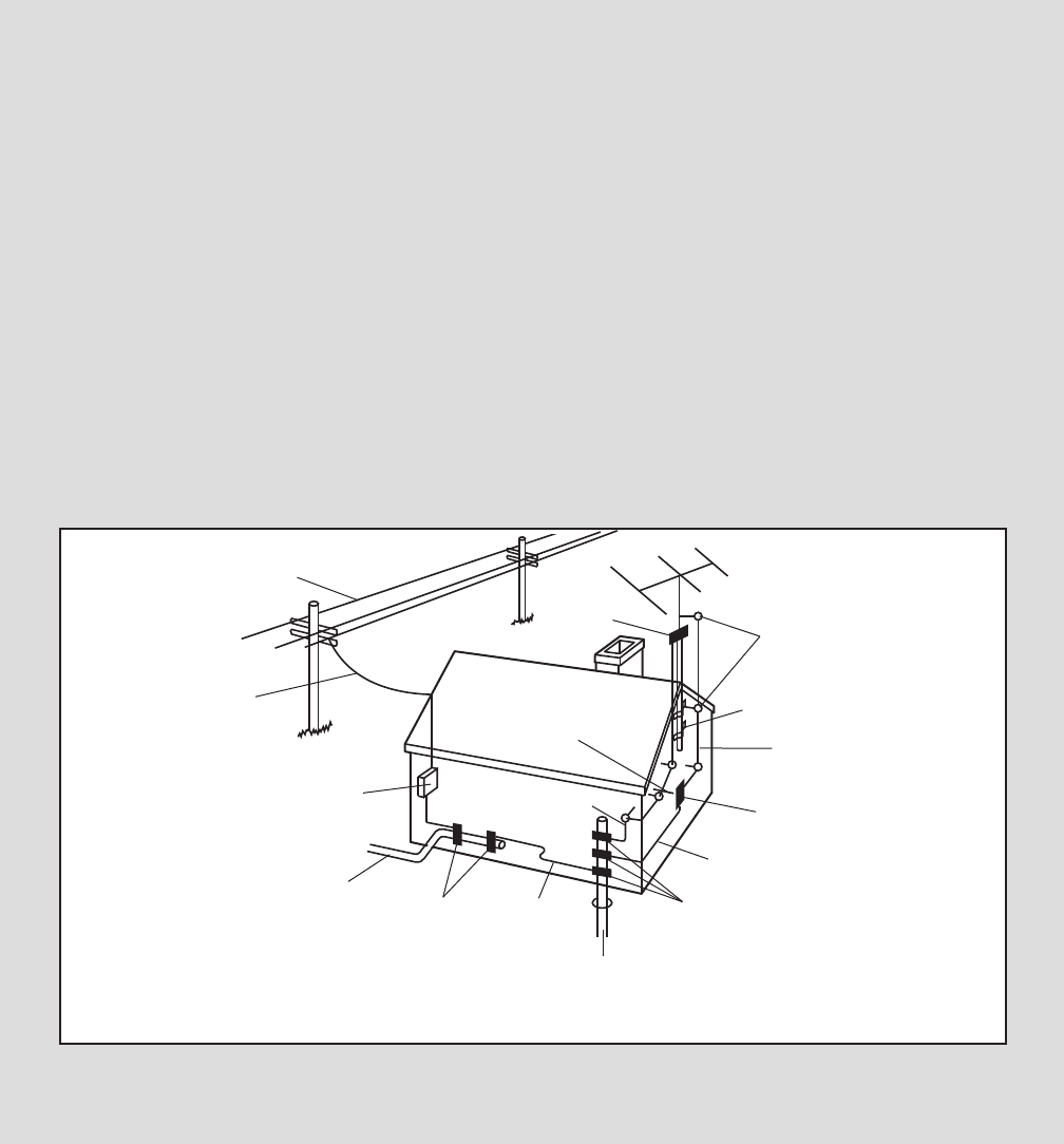
31. If an outside antenna or cable system is con-
nected, be sure that the antenna or cable sys-
tem is grounded to provide some protection
against voltage surges and built-up static
charges. Section 810 of the National
Electrical Code, ANSI/NFPA No. 70-1984, pro-
vides information with respect to proper
grounding of the mast and supporting struc-
ture, grounding of the lead-in wire to an an-
tenna discharge unit, size of grounding con-
ductors, location of antenna discharge unit,
connection to grounding electrodes, and re-
quirements for the grounding electrode.
32. An outside antenna system should not be lo-
cated in the vicinity of overhead power lines
or other electric light or power circuits, or
where it can fall into such power lines or cir-
cuits. When installing an outside antenna sys-
tem, extreme care should be taken to keep
from touching such power lines or circuits, as
contact with them might be fatal.
33. To reduce the risk of electric shock, do not re-
move the cover or the back of the television.
There are no user serviceable parts inside.
Refer servicing to qualified service personnel.
5
SAVE THESE INSTRUCTIONS
Power Lines
Ground
Clamps
Ground
Clamps
Ground
Clamp
Bonding
Jumper
Standoff
Insulators
Antenna
Lead-in Wire
Ground Wire
Ground
Wire
Antenna
Discharge Unit
To External 75 Ohm
Terminal of Treadmill
Mast
Service
Entrance
Equipment
Power Service Grounding
Electrode System (e.g.
Interior Metal Water Pipe)
Service
Entrance
Conductors
Optional Antenna Grounding Electrode Driven 8
Feet (2.44 m) Into The Earth (If Required By Local
Codes). See NEC Section 810–21 (f).
34. Upon completion of any service or repairs to
the treadmill or the television, ask the service
technician to perform safety checks to con-
firm that the unit is in proper operating condi-
tion.
• Use No. 10 AWG (5.3 mm2) copper, No. 8
AWG (8.4 mm2)aluminum, No. 17 AWG (1.0
mm2) copper-clad steel or bronze wire, or
larger as a ground wire.
• Secure an antenna lead-in and ground
wires to the house with stand-off insulators
spaced from 4 to 6 feet (1.22 to 1.83 m)
apart.
• Mount an antenna discharge unit as close
as possible to where the lead-in enters the
house.
• Use a jumper wire not smaller than No. 6
AWG (13.3 mm2) copper, or the equivalent
when a separate antenna-grounding elec-
trode is used. See NEC Section 810-21 (j).
Note to CATV system installer: This reminder is
provided to call the CATV system installerʼs at-
tention to Article 820-40 of the NEC that provides
guidelines for proper grounding and, in particu-
lar, specifies that the cable ground shall be con-
nected to the grounding system of the building,
as close to the point of cable entry as practical.
6
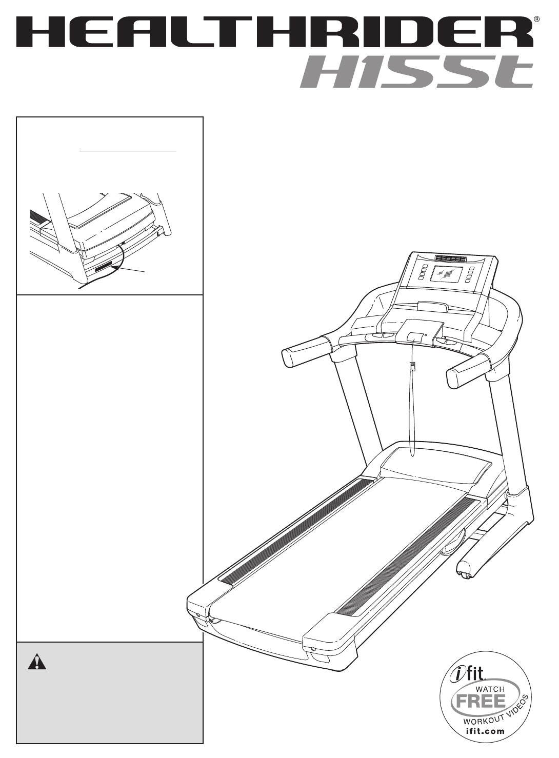
Thank you for selecting the revolutionary HealthRider®
H155T treadmill. The H155T treadmill offers an im-
pressive selection of features designed to make your
workouts at home more enjoyable and effective. And
when youʼre not exercising, the unique treadmill can be
folded up, requiring less than half the floor space of
other treadmills.
For your benefit, read this manual carefully before
using the treadmill. If you have questions after read-
ing this manual, please see the front cover of this man-
ual. To help us assist you, note the product model
number and serial number before contacting us. The
model number and the location of the serial number
decal are shown on the front cover of this manual.
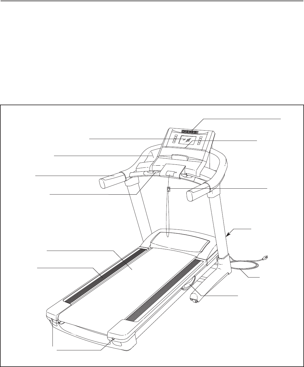
Before reading further, please look at the drawing
below and familiarize yourself with the labeled parts.
BEFORE YOU BEGIN
Handrail
Fan
Personal Television/Console Book Holder
Key/Clip
Reset/Off
Circuit Breaker
Walking Belt
Foot Rail
Power Cord
Adjustable Cushion
Idler Roller
Adjustment Bolts
Accessory Tray
Pulse Sensor
7
ASSEMBLY
To hire an authorized service technician to assemble the treadmill, call toll-free 1-800-445-2480. Assembly
requires two persons. Set the treadmill in a cleared area and remove all packing materials. Do not dispose of
the packing materials until assembly is completed. Note: The underside of the treadmill walking belt is coated
with high-performance lubricant. During shipping, some lubricant may be transferred to the top of the walking belt
or the shipping carton. This is normal and does not affect treadmill performance. If there is lubricant on top of the
walking belt, simply wipe off the lubricant with a soft cloth and a mild, non-abrasive cleaner.
Assembly requires the included hex keys and your own Phillips screwdriver and adjustable
wrench .
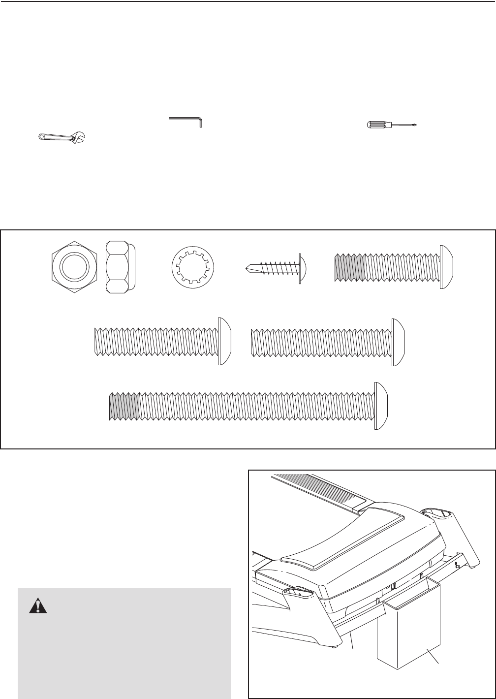
Use the drawings below to identify the assembly hardware. The number in parentheses below each drawing is
the key number of the part, from the PART LIST near the end of this manual. The number after the parentheses
is the quantity needed for assembly. Note: If a part is not in the hardware kit, check to see if it is preattached
to one of the parts to be assembled. To avoid damaging plastic parts, do not use power tools for assem-
bly. Extra hardware may be included.
3/8" Star Washer
(6)–10
3/8" x 3 3/4" Patch Bolt (5)–4
3/8" Jam Nut (7)–2
#8 x 3/4"
Tek Screw (24)–4
3/8" x 1 1/4"
Patch Bolt (2)–6
3/8" x 2" Bolt (4)–1
3/8" x 1 3/4" Bolt (3)–1
103
Cardboard
Stand
1
1. Make sure that the power cord is unplugged.
With the help of a second person, raise the front
of the treadmill and insert the crossbar on the
Base (103) into the cutout in the cardboard
stand as shown. Have the second person
hold the treadmill to prevent it from moving
forward or backward until assembly step 3 is
completed.
WARNING: Serious injury
may occur if the treadmill moves for-
ward or backward and falls off the card-
board stand. A second person must
hold the treadmill until assembly step 3
is completed to prevent the treadmill
from moving, tipping, or falling.
8
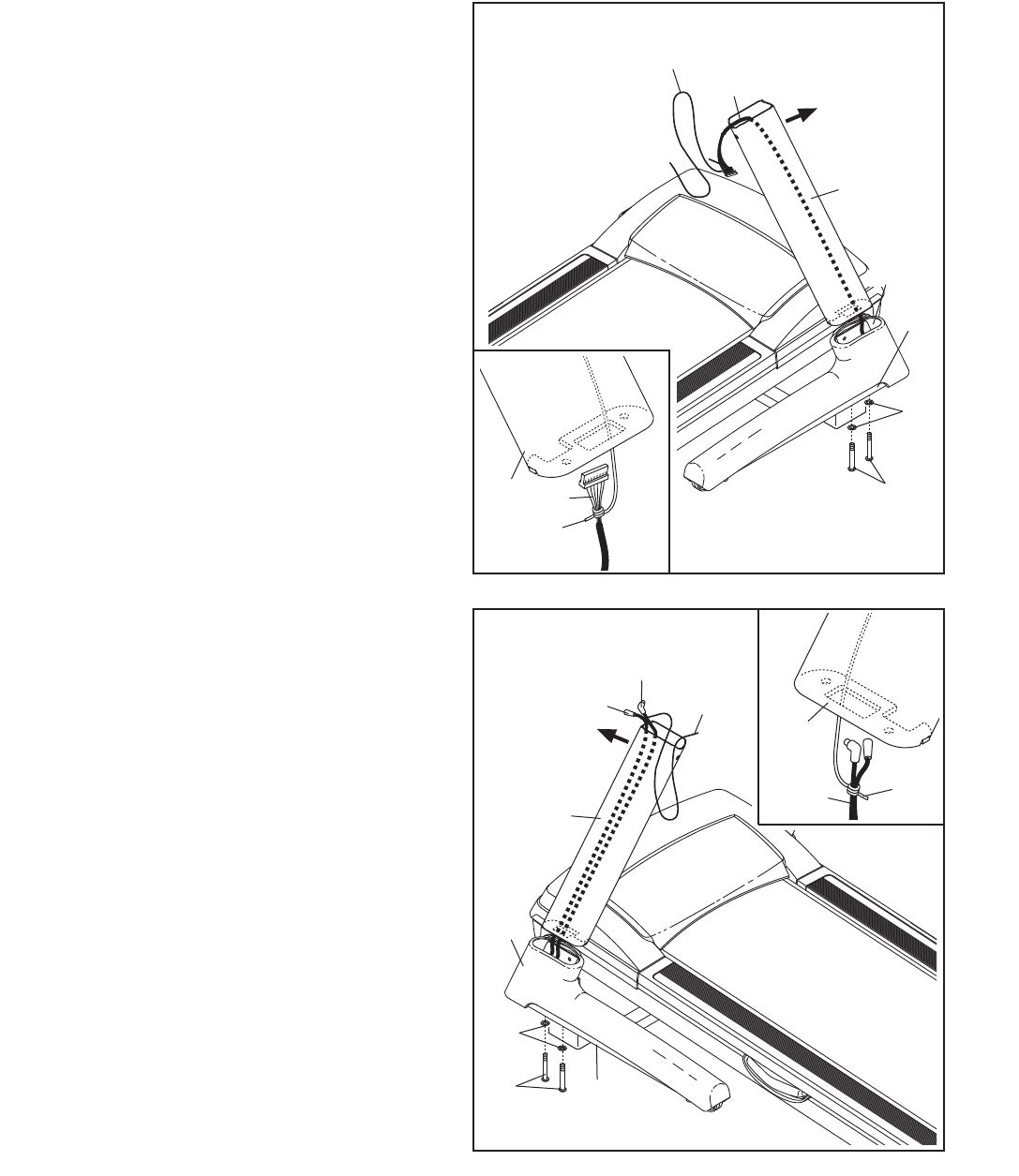
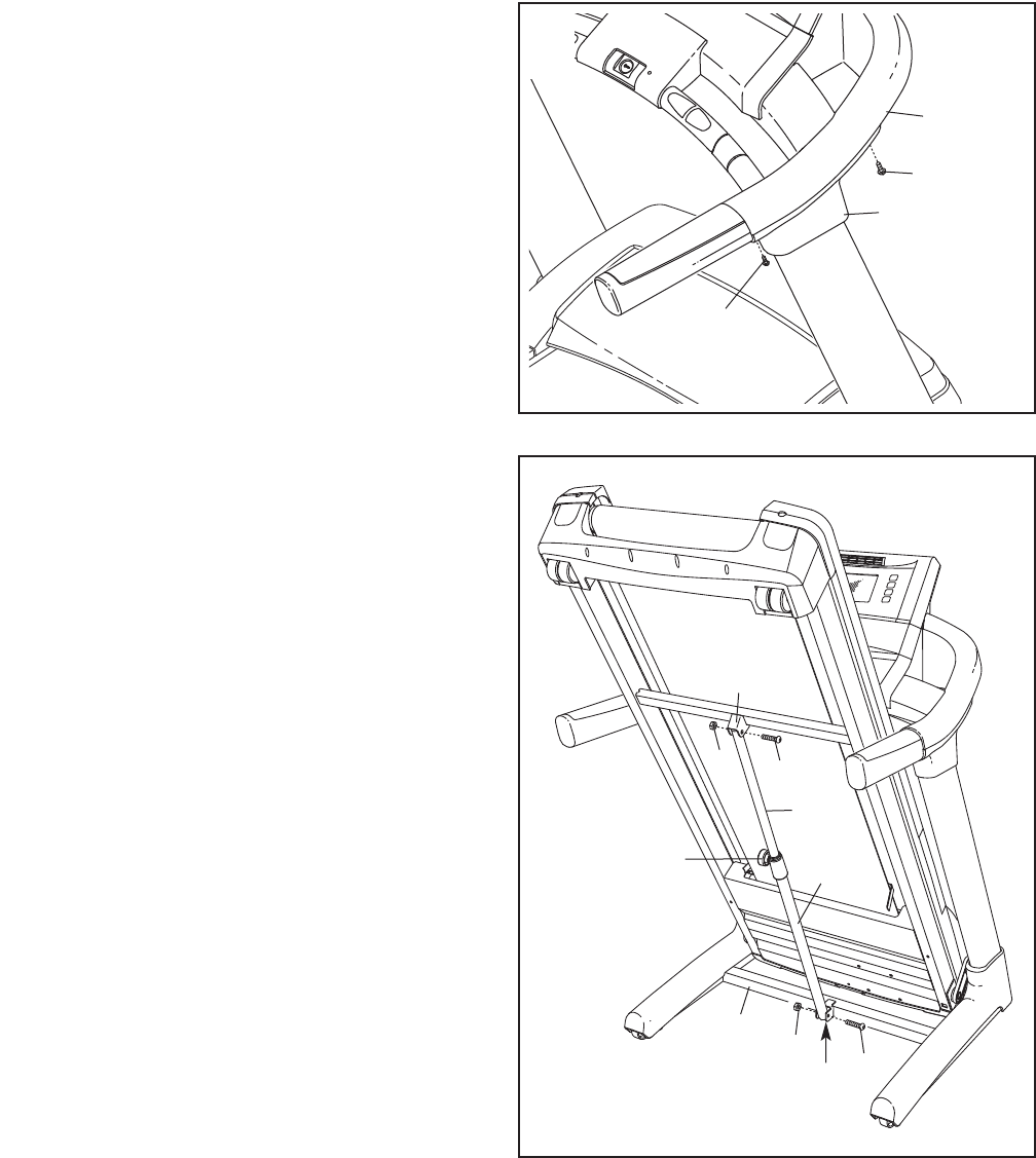
2. Identify the Right Upright (92) which is marked
with a “Right” sticker.
Have a second person hold the Right Upright
(92) near the Right Base Cover (102). See the
inset drawing. Tie the wire tie in the lower end
of the Right Upright securely around the end of
the Upright Wire (93). Then, pull the other end
of the wire tie up through the top of the Right
Upright until the Upright Wire is routed com-
pletely through the Right Upright.
Gently pull up on the Upright Wire (93) as you
set the Right Upright (92) on the Base (103) in-
side the Right Base Cover (102). Be careful not
to pinch the Upright Wire.
Attach the Right Upright (92) to the Base (103)
with two 3/8" x 3 3/4" Patch Bolts (5) and two
3/8" Star Washers (6). Note: It may be neces-
sary to tip the top of the Right Upright forward
slightly as you thread the Bolts into it. Do not
tighten the Bolts yet.
103
93
102
2
92
6
5
93
92
Wire
Tie
3. Have a second person hold the Left Upright (91)
near the Left Base Cover (100). See the inset
drawing. Tie the wire tie in the Left Upright se-
curely around the end of the TV Cable (95) and
the AV Cable (94). Then, pull the other end of
the wire tie up through the top of the Left Upright
until the TV Cable and the AV Cable are routed
completely through the Left Upright.
Gently pull up on the TV Cable (95) and the AV
Cable (94) as you set the Left Upright (91) on
the Base (103) inside the Left Base Cover (100).
Be careful not to pinch the Cables.
Attach the Left Upright (91) to the Base (103)
with two 3/8" x 3 3/4" Bolts (5) and two 3/8" Star
Washers (6). Note: It may be necessary to tip
the top of the Left Upright forward slightly as you
thread the Bolts into it. Do not tighten the
Bolts yet.
With the help of a second person, lower the
treadmill off the cardboard stand. Save the card-
board stand for step 10.
103
100
3
91
95
94
6
5
94, 95
91
Wire
Tie
Wire
Tie
Wire
Tie
9
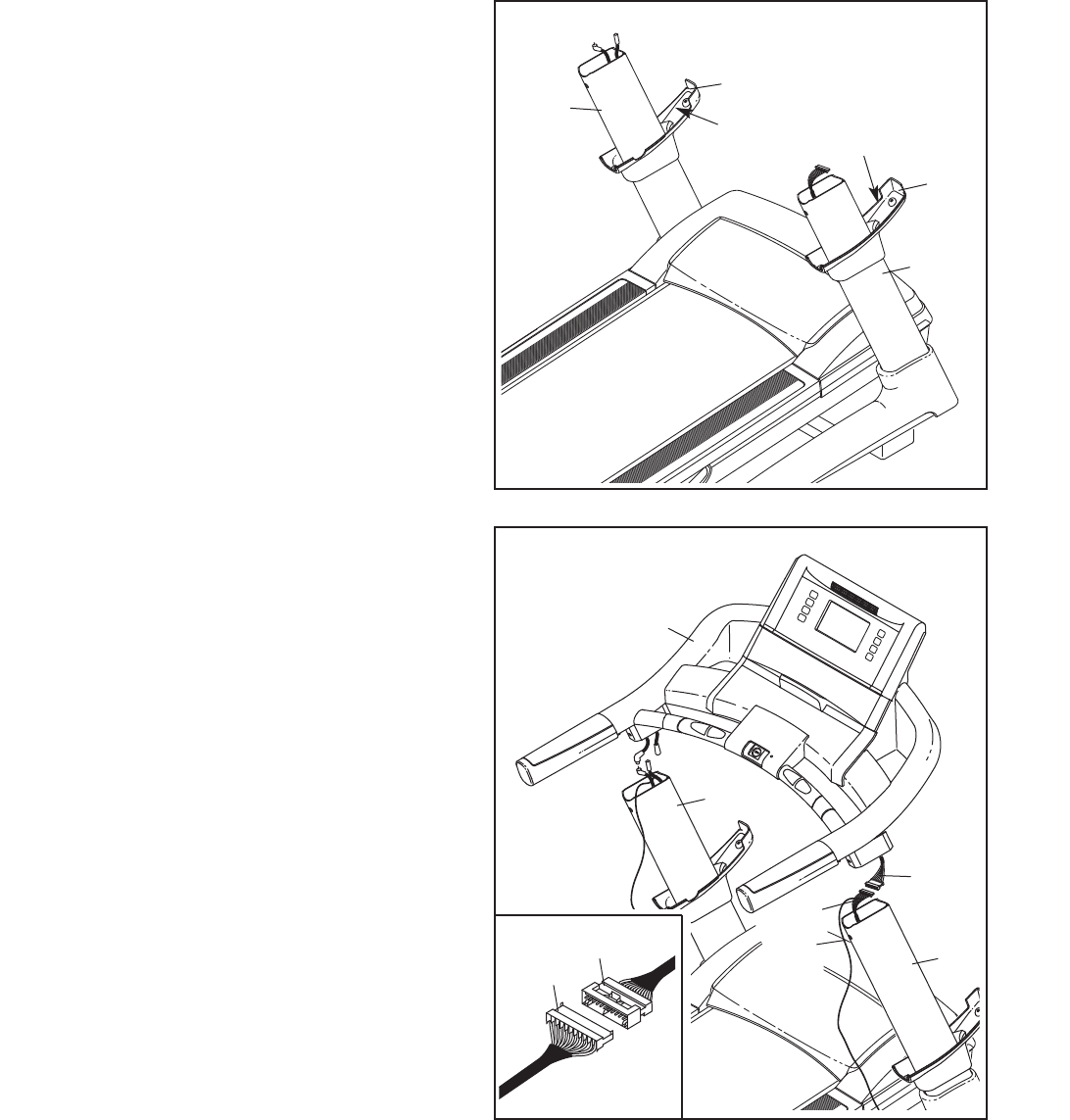
4. Identify the Right Upright Sleeve (90) and the
Left Upright Sleeve (89); the Upright Sleeves
are labeled “Right” and “Left.” Slide the Right
Upright Sleeve onto the Right Upright (92) and
the Left Upright Sleeve onto the Left Upright
(91).
89
“Right”
“Left”
90
4
92
91
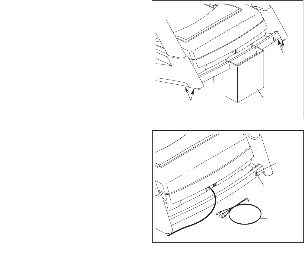
5. Have a second person hold the console assem-
bly near the Uprights (91, 92).
Connect the Upright Wire (93) to the Console
Wire (120). See the inset drawing. The con-
nectors should slide together easily and
snap into place. If they do not, turn one con-
nector and try again. IF THE CONNECTORS
ARE NOT CONNECTED PROPERLY, THE
CONSOLE MAY BE DAMAGED WHEN THE
POWER IS TURNED ON. Remove the wire tie
from the Upright Wire. Insert the connectors
down into the Right Upright (92).
120
Console
Assembly
5
92
93
91
120 Wire
Tie
93
10
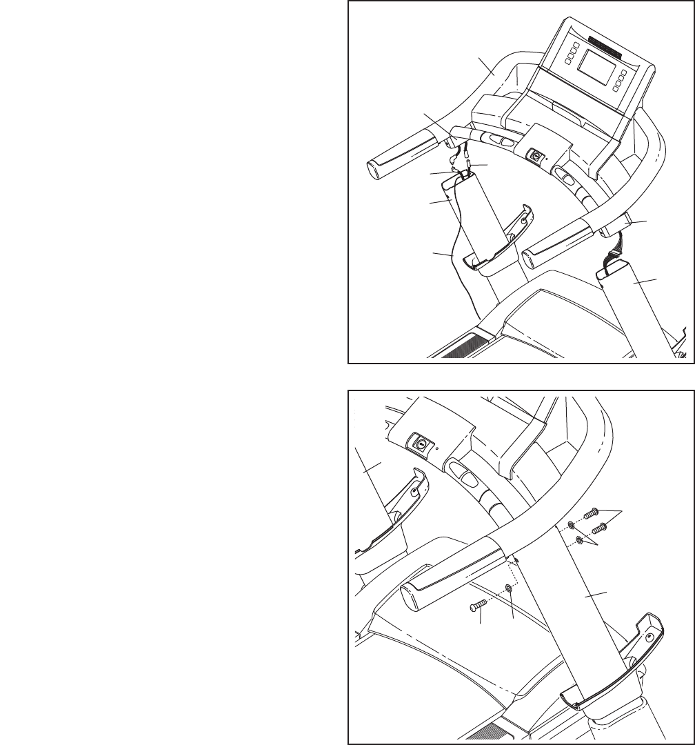
6. Connect the TV Cable (95) and the AV Cable
(94) to the cables extending from the console
assembly. Remove the wire tie from the TV
Cable and the AV Cable. Then, insert the con-
nectors down into the Left Upright (91).
Next, insert the brackets on the Handrails (110)
into the Uprights (91, 92). Make sure that no
wires are pinched.
95
91
94
6
92
110
7. Partially tighten three 3/8" x 1 1/4" Patch Bolts
(2) with three 3/8" Star Washers (6) into the
Right Upright (92).
Repeat this step with the Left Upright (91).
Then, firmly tighten all six 3/8" x 1 1/4" Patch
Bolts (2).
91
92
2
2
6
6
7
110
Console
Assembly
Wire
Tie
11
8. Slide the Right Upright Sleeve (90) up against
the console assembly. Attach the Right Upright
Sleeve with two #8 x 3/4" Tek Screws (24).
Attach the Left Upright Sleeve (not shown) to
the console assembly in the same way.
24
90
24
8
Console
Assembly
9. Orient the Storage Latch (87) so that the large
barrel and the Latch Knob (88) are in the posi-
tions shown.
Remove the tie from the upper end of the
Storage Latch (87). Attach the upper end of the
Storage Latch to the bracket on the Frame (67)
with a 3/8" x 1 3/4" Bolt (3) and a 3/8" Jam Nut
(7).
Remove the tie from the lower end of the
Storage Latch (87). Keep the holes in the Latch
Cap (86) aligned with the holes in the Storage
Latch. Make sure to keep the Latch Cap in-
side the Storage Latch. Attach the Storage
Latch to the bracket on the Base (103) with a
3/8" x 2" Bolt (4) and a 3/8" Jam Nut (7). Note: It
may be necessary to move the Frame back and
forth to align the Storage Latch with the bracket.
Lower the Frame (67) (see HOW TO LOWER
THE TREADMILL FOR USE on page 27).
7
7
Large
Barrel
103
86 4
67
3
88
87
9
12
11. Note the location of the 75 ohm terminal and the
audio/video input jack on the treadmill. For the
television to operate, an antenna or a CATV
cable must be connected to the 75 ohm terminal
or the included AV Wire (96) must be connected
to the audio/video input jack (see page 13).
11
12. Make sure that all parts are properly tightened before you use the treadmill. Keep the included hex keys
in a secure place; one of the hex keys is used to adjust the walking belt (see pages 29 and 30). To protect
the floor or carpet from damage, place a mat under the treadmill.
75 Ohm
Terminal
Audio/
Video
Input
96
10. With the help of a second person, raise the
front of the treadmill and insert the crossbar on
the Base (103) into the cutout in the cardboard
stand as shown. Have the second person
hold the treadmill to prevent it from moving
forward or backward.
Firmly tighten the four 3/8" x 3 3/4" Bolts (5).
With the help of the second person, lower the
treadmill off the cardboard stand.
Cardboard
Stand
5
103
5
10
13
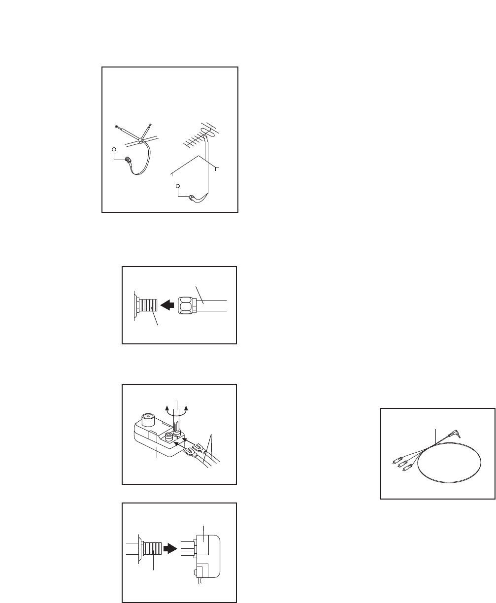
HOW TO CONNECT AN ANTENNA
Place an indoor an-
tenna or an outdoor
combination
VHF/UHF antenna
in the desired loca-
tion. Outdoor anten-
nas are subject to
weathering that can
reduce signal qual-
ity. Inspect your out-
door antenna and
the lead-in wiring
before connecting
the antenna.
75 Ohm CATV Cable
1. Connect the 75 ohm
CATV cable from the
antenna to the 75
ohm terminal on the
treadmill frame near
the power cord.
300 Ohm Flat Wire
1. Connect the 300
ohm flat wire from
the antenna to a
300 ohm to 75 ohm
adapter.
2. Connect the 300
ohm to 75 ohm
adapter to the 75
ohm terminal on the
treadmill frame near
the power cord.
Note: Due to an FCC requirement, analog signals will
no longer be broadcast over the air after June 12,
2009. If you wish to view television signals through an
antenna after that date, you must have an antenna ca-
pable of receiving digital signals or a digital converter
box. Cable television will not be affected.
HOW TO CONNECT AN EXTERNAL SOURCE
USING A CATV CABLE
Use a CATV cable to connect to an external source
such as a cable box, satellite TV box, VCR, or analog
cable.
1. Connect one end of a 75 ohm CATV cable to the
75 ohm output jack on your external source.
2. Plug in the power cord of your external source.
See your external source userʼs manual for proper
grounding instructions.
3. Connect the 75 ohm CATV cable to the 75 ohm
terminal on the treadmill frame near the power
cord. See the drawing at the left.
HOW TO CONNECT AN EXTERNAL SOURCE
USING THE A/V WIRE
Use the A/V Wire to connect to an external source such
as a VCR or DVD player.
1. Connect the three-
pronged end of the
A/V Wire (96) to your
external source.
2. Plug in the power cord of your external source.
See your external source userʼs manual for proper
grounding instructions.
3. Connect the A/V Wire to the audio/video input jack
on the treadmill frame near the power cord.
300 to 75
Ohm Adapter
Screwdriver
300
Ohm Flat
Wire
75 Ohm Terminal
75 Ohm CATV Cable
Outdoor
Combination
VHF/UHF
Antenna
Indoor
Antenna
Before operating the television, you must connect an antenna or a 75 ohm CATV cable to the 75 ohm ter-
minal or the A/V Wire to the audio/video input jack. No CATV cable, antenna, or adapter is included.
75 Ohm
Terminal
300 to 75 Ohm Adapter
96
OPERATION AND ADJUSTMENT
THE PRE-LUBRICATED WALKING BELT
Your treadmill features a walking belt coated with high-
performance lubricant. IMPORTANT: Never apply sil-
icone spray or other substances to the walking
belt or the walking platform. Such substances will
deteriorate the walking belt and cause excessive
wear.
HOW TO PLUG IN THE POWER CORD
Your treadmill, like any other type of sophisticated
electronic equipment, can be seriously damaged by
sudden voltage changes in your homeʼs power.
Voltage surges, spikes, and noise interference can
result from weather conditions or from other appli-
ances being turned on or off. To decrease the possi-
bility of your treadmill being damaged, always use
a surge suppressor with your treadmill (see draw-
ing 1 at the right). To purchase a surge suppres-
sor, see your local HealthRider dealer or call the
telephone number on the front cover of this man-
ual and order part number 146148, or see your
local electronics store.
Use only a single-outlet surge suppressor that is
UL 1449 listed as a transient voltage surge sup-
pressor (TVSS). The surge suppressor must have a
UL suppressed voltage rating of 400 volts or less
and a minimum surge dissipation of 450 joules.
The surge suppressor must be electrically rated for
120 volts AC and 15 amps. There must be a moni-
toring light on the surge suppressor to indicate
whether it is functioning properly. Failure to use a
properly functioning surge suppressor could result
in damage to the control system of the treadmill. If
the control system is damaged, the walking belt
may slow, accelerate, or stop unexpectedly, which
may result in a fall and serious injury.
This product must be grounded. If it should malfunc-
tion or break down, grounding provides a path of least
resistance for electric current to reduce the risk of elec-
tric shock. This product is equipped with a cord having
an equipment-grounding conductor and a grounding
plug. Plug the power cord into a surge suppressor,
and plug the surge suppressor into an appropriate
outlet that is properly installed and grounded in
accordance with all local codes and ordinances.
IMPORTANT: The treadmill is not compatible with
GFCI-equipped outlets.
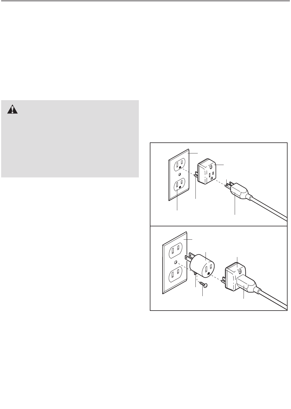
This product is for use on a nominal 120-volt circuit,
and has a grounding plug that looks like the plug illus-
trated in drawing 1 below. A temporary adapter that
looks like the adapter illustrated in drawing 2 may be
used to connect the surge suppressor to a 2-pole
receptacle as shown in drawing 2 if a properly
grounded outlet is not available.
The temporary adapter should be used only until a
properly grounded outlet (drawing 1) can be installed
by a qualified electrician.
The green-colored rigid ear, lug, or the like extending
from the adapter must be connected to a permanent
ground such as a properly grounded outlet box cover.
Whenever the adapter is used it must be held in place
by a metal screw. Some 2-pole receptacle outlet box
covers are not grounded. Contact a qualified elec-
trician to determine if the outlet box cover is
grounded before using an adapter.
DANGER: Improper connection
of the equipment-grounding conductor can
result in an increased risk of electric shock.
Check with a qualified electrician or service-
man if you are in doubt as to whether the
product is properly grounded. Do not modify
the plug provided with the product—if it will
not fit the outlet, have a proper outlet
installed by a qualified electrician.
1
2
Grounded Outlet Box
Grounded Outlet Box
Grounding Plug
Surge Suppressor
Surge Suppressor
Grounding Pin
Adapter
Lug
Metal Screw
Grounded Outlet
Grounding Pin
14
Grounding Plug
15
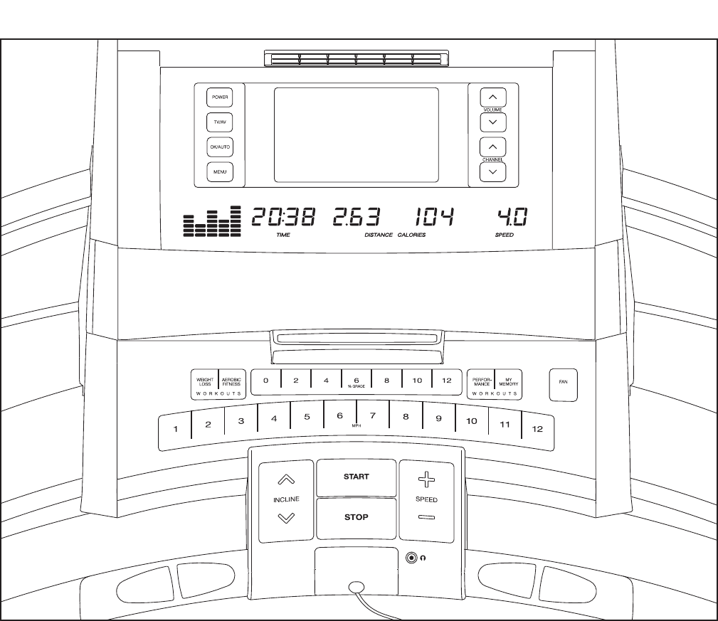
FEATURES OF THE CONSOLE
The treadmill console offers an impressive selection of
features designed to make your workouts more effec-
tive and enjoyable. When the manual mode of the con-
sole is selected, the speed and incline of the treadmill
can be changed with the touch of a button. As you ex-
ercise, the console will display continuous exercise
feedback. You can even measure your heart rate using
the handgrip pulse sensor.
In addition, the console features twenty-eight preset
workouts—ten weight loss workouts, nine aerobic fit-
ness workouts, and nine performance workouts. Each
workout automatically controls the speed and incline of
the treadmill as it guides you through an effective exer-
cise session. You can even create your own my mem-
ory workouts and save them for future use.
Whether you select the manual mode or a workout,
you can enjoy the shows of your choice on the per-
sonal television while you get in shape. You can also
listen to your favorite workout music or audio books
with the consoleʼs premium stereo sound system.
To turn on the power, see page 16. To use the man-
ual mode, see page 16. To use a preset workout,
see page 18. To create and use a my memory work-
out, see pages 19 and 20. To operate the personal
television, see page 21. To use the remote control,
see page 22. To replace the batteries in the remote
control, see page 22. To adjust television settings,
see page 23. To use the information mode, see
page 25. To use the stereo sound system, see page
25.
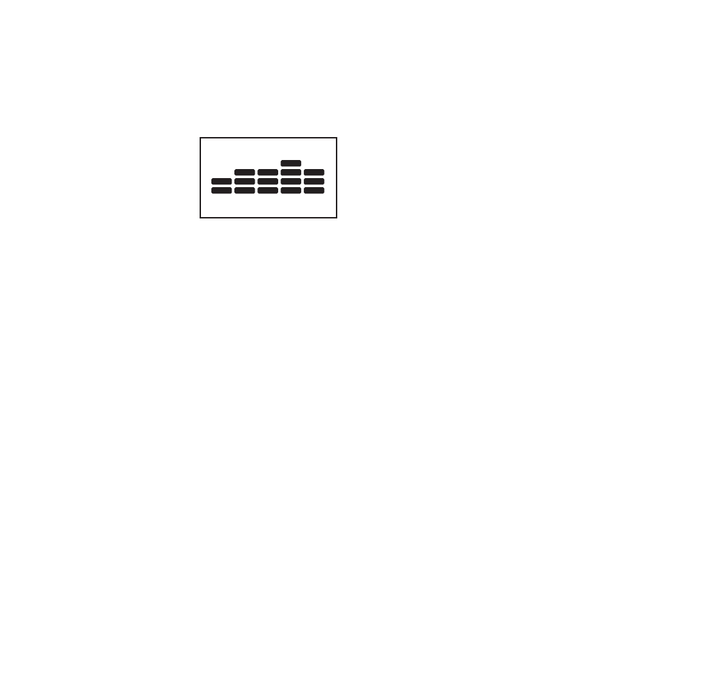
CONSOLE DIAGRAM
16
HOW TO TURN ON THE POWER
IMPORTANT: If the treadmill has been exposed to
cold temperatures, allow it to warm to room tem-
perature before turning on the power. If you do not
do this, you may damage the console displays or
other electrical components.
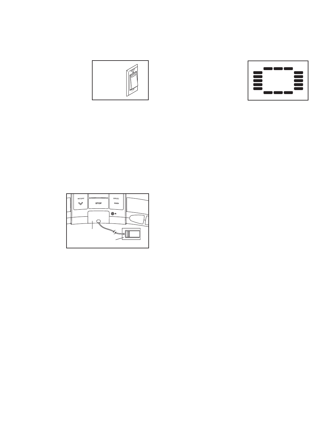
Plug in the power cord (see
page 14). Next, locate the
reset/off circuit breaker on
the treadmill frame near the
power cord. Make sure that
the circuit breaker is in the
reset position.
IMPORTANT: The console features a display demo
mode, designed to be used if the treadmill is dis-
played in a store. If the displays light as soon as
you plug in the power cord and switch the reset/off
circuit breaker to the reset position, the demo
mode is turned on. To turn off the demo mode,
hold down the Stop button for a few seconds. If the
displays remain lit, see THE INFORMATION MODE
on page 25 to turn off the demo mode.
Next, stand on the
foot rails of the
treadmill. Locate
the clip attached to
the key (see the
drawing at the
right), and slide
the clip securely
onto the waistband
of your clothes. Then, insert the key into the console.
After a moment, the displays will light. IMPORTANT:
In an emergency situation, the key can be pulled
from the console, causing the walking belt to slow
to a stop. Test the clip by carefully taking a few
steps backward; if the key is not pulled from the
console, adjust the position of the clip.
IMPORTANT: If there is a sheet of clear plastic on
the face of the console, remove the plastic. To pre-
vent damage to the walking platform, wear clean
athletic shoes while using the treadmill. The first
time the treadmill is used, observe the alignment
of the walking belt, and center the walking belt if
necessary (see page 29).
Note: The console can display speed and distance in
either miles or kilometers. To find out which unit of
measurement is selected or to change the unit of mea-
surement, see THE INFORMATION MODE on page
25. For simplicity, all instructions in this section refer to
miles.
HOW TO USE THE MANUAL MODE
1. Insert the key into the console.
See HOW TO TURN ON THE POWER at the left.
2. Select the manual mode.
Each time the key is in-
serted, the manual mode
will be selected. If you
have selected a workout,
press any of the workout
buttons (Weight Loss,
Aerobic Fitness,
Performance, or My Memory) repeatedly until a
track appears in the matrix.
3. Start the walking belt and adjust the speed.
To start the walking belt, press the Start button, the
Speed increase button, or one of the speed but-
tons numbered 1 to 12.
If you press the Start button or the Speed increase
button, the walking belt will begin to move at 1
mph. As you exercise, change the speed of the
walking belt as desired by pressing the Speed in-
crease and decrease buttons. Each time you press
one of the buttons, the speed setting will change
by 0.1 mph; if you hold down the button, the speed
setting will change in increments of 0.5 mph. If you
press one of the numbered speed buttons, the
walking belt will gradually change speed until it
reaches the selected speed setting.
To stop the walking belt, press the Stop button. To
restart the walking belt, press the Start button, the
Speed increase button, or one of the numbered
speed buttons.
4. Change the incline of the treadmill as desired.
To change the incline of the treadmill, press the
Incline increase and decrease buttons or one of
the incline buttons numbered 0 to 12.
Each time you press the Incline increase or de-
crease button, the incline will change by 0.5%. If
you press one of the numbered incline buttons, the
incline will gradually change until it reaches the se-
lected incline setting. Note: After you press the but-
tons, it may take a moment for the treadmill to
reach the selected incline setting.
Reset
Clip
Key
17
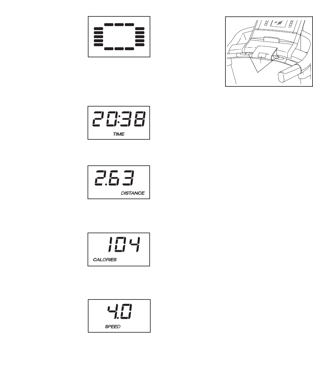
5. Follow your progress with the displays.
The matrix—When you
select the manual
mode, the matrix will
display a track that rep-
resents 1/4 mile (400
meters). As you exer-
cise, the indicators
around the track will appear in succession until the
entire track appears. The track will then disappear
and the indicators will again begin to appear in
succession.
The Time display—
The Time display will
show the elapsed time.
Note: When a workout
is selected, the display
will show the time re-
maining in the workout instead of the elapsed time.
The Distance/Incline
display—The
Distance/Incline display
can show the distance
that you have walked or
run. The display will
also show the incline of the treadmill for several
seconds each time the incline changes.
The Calorie/Pulse dis-
play—The
Calorie/Pulse display
can show the approxi-
mate number of calories
you have burned. The
display will also show your heart rate when you
use the handgrip pulse sensor.
The Speed display—
The Speed display will
show the speed of the
walking belt.
To reset the console, press the Stop button, re-
move the key, and then reinsert the key.
6. Measure your heart rate if desired.
Before using
the handgrip
pulse sensor,
remove the
sheets of clear
plastic from the
metal contacts.
In addition,
make sure that
your hands are
clean.
To measure your heart rate, stand on the foot
rails and hold the metal contacts on the handrail—
avoid moving your hands. Hold the contacts for
approximately ten seconds. When your pulse is
detected, several dashes will appear in the display
and then your heart rate will be shown. For the
most accurate heart rate reading, continue to
hold the contacts for about 15 seconds.
7. Turn on the fan if desired.
The fan features high and low speed settings.
Press the Fan button repeatedly to select a fan
speed or to turn off the fan. Note: If the fan is on
when the walking belt is stopped, the fan will turn
off automatically after a few minutes.
8. When you are finished exercising, remove the
key from the console.
Step onto the foot rails, press the Stop button, and
adjust the incline of the treadmill to the lowest
setting. The incline must be at the lowest set-
ting when you fold the treadmill to the storage
position, or you may damage the treadmill.
Next, remove the key from the console and put it in
a secure place.
When you are finished using the treadmill, switch
the reset/off circuit breaker to the off position and
unplug the power cord. IMPORTANT: If you do
not do this, the treadmillʼs electrical compo-
nents may wear prematurely.
Contacts
18
HOW TO USE A PRESET WORKOUT
1. Insert the key into the console.
See HOW TO TURN ON THE POWER on page 16.
2. Select a preset workout.
To select a preset workout, press the Weight Loss
button, the Aerobic Fitness button, or the
Performance button repeatedly.
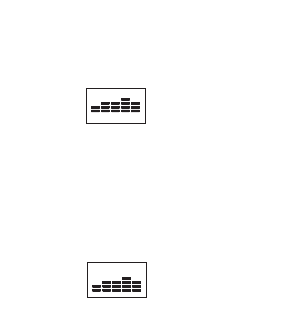
When a preset workout
is selected, the displays
will show the duration of
the workout, the maxi-
mum incline setting, the
workout number, and
the maximum speed setting of the workout. In addi-
tion, a profile of the speed settings of the workout
will scroll across the matrix.
3. Start the workout.
Press the Start button to start the workout. A mo-
ment after you press the button, the treadmill will
automatically adjust to the first speed and incline
settings of the workout. Hold the handrails and
begin walking.
Each workout is divided into one-minute segments.
One speed setting and one incline setting are pro-
grammed for each segment. Note: The same
speed and/or incline setting may be programmed
for consecutive segments.
During the workout, the
profile will show your
progress. The flashing
segment of the profile
represents the current
segment of the workout.
The height of the flashing segment indicates the
speed setting for the current segment. At the end
of each segment, a series of tones will sound and
the next segment of the profile will begin to flash. If
a new speed or incline setting is programmed for
the next segment, the new speed or incline setting
will appear in the displays for a few seconds. The
treadmill will then automatically adjust to the speed
and incline settings for the next segment.
If the speed or incline setting is too high or too low
at any time during the workout, you can manually
override the setting by pressing the speed or in-
cline buttons; however, when the next segment
of the workout begins, the treadmill will auto-
matically adjust to the speed and incline set-
tings for the next segment.
To stop the workout at any time, press the Stop
button. To restart the workout, press the Start but-
ton or the Speed increase button. The walking belt
will begin to move at 1 mph. When the next seg-
ment of the workout begins, the treadmill will auto-
matically adjust to the speed and incline settings
for the next segment.
The workout will continue in this way until the last
segment of the workout ends. The walking belt will
then slow to a stop.
4. Follow your progress with the displays.
See step 5 on page 17.
5. Measure your heart rate if desired.
See step 6 on page 17.
6. Turn on the fan if desired.
See step 7 on page 17.
7. When you are finished exercising, remove the
key from the console.
See step 8 on page 17.
Current Segment

19
HOW TO CREATE A MY MEMORY WORKOUT
1. Insert the key into the console.
See HOW TO TURN ON THE POWER on page 16.
2. Select a my memory workout.
To select a my memory
workout, press the My
Memory button repeat-
edly. When a my mem-
ory workout is selected,
the displays will show
the duration of the work-
out, the maximum incline setting, the workout num-
ber, and the maximum speed setting of the work-
out. In addition, three columns of indicators will ap-
pear in the displays.
Note: If more than three columns of indicators
scroll across the matrix, see HOW TO USE A
MY MEMORY WORKOUT on page 20.
3. Start the workout and program the desired
speed and incline settings.
Press the Start to start the workout. A moment after
you press the button, the walking belt will begin to
move. Hold the handrails and begin walking.
Each my memory workout is divided into several
one-minute segments. One speed setting and one
incline setting can be programmed for each seg-
ment. To program speed and incline settings for
the first segment, simply adjust the speed and in-
cline of the treadmill as desired by pressing the
speed and incline buttons.
When the first segment of the workout ends, a se-
ries of tones will sound and the current speed and
incline settings will be saved in memory. Program
a speed setting and an incline setting for the sec-
ond segment in the same way.
Continue programming speed and incline settings
for as many segments as desired; my memory
workouts can have up to forty segments. When
you are finished with your workout, press the Stop
button twice. The speed and incline settings that
you have programmed and the workout duration
will then be saved in memory.
4. Follow your progress with the displays.
See step 5 on page 17.
5. Measure your heart rate if desired.
See step 6 on page 17.
6. Turn on the fan if desired.
See step 7 on page 17.
7. When you are finished exercising, remove the
key from the console.
See step 8 on page 17.
20
HOW TO USE A MY MEMORY WORKOUT
1. Insert the key into the console.
See HOW TO TURN ON THE POWER on page 16.
2. Select a my memory workout.
To select a my memory
workout, press the My
Memory button repeat-
edly. When a my mem-
ory workout is selected,
the duration of the work-
out, the maximum incline setting, the workout num-
ber, and the maximum speed setting of the work-
out will appear. In addition, a profile of the speed
settings of the workout will scroll across the matrix.
Note: If only three columns of indicators scroll
across the matrix, see HOW TO CREATE A MY
MEMORY WORKOUT on page 19.
3. Start the workout.
Press the Start button to start the workout. A mo-
ment after you press the button, the treadmill will
automatically adjust to the first speed and incline
settings that you programmed previously. Hold the
handrails and begin walking.
Each my memory workout is divided into several
one-minute segments. One speed setting and one
incline setting are programmed for each segment.
Note: The same speed and/or incline setting may
be programmed for consecutive segments.
The my memory workout will function in the same
way as a preset workout (see step 3 on page 18).
If desired, you can redesign the workout while using
it. To change the speed setting or the incline
setting for the current segment, simply press the
speed or incline buttons. When the current segment
ends, the new setting will be saved in memory. To
increase the length of the workout, first wait until
the workout is completed. Then, press the Start but-
ton and program speed and incline settings for as
many additional segments as desired. When you
have added as many segments as desired, press
the Stop button twice. To decrease the length of
the workout, press the Stop button twice at any
time before the workout is completed.
To stop the workout temporarily, press the Stop
button. To restart the workout, press the Start but-
ton. The walking belt will begin to move at 1 mph.
When the next segment of the workout begins, the
treadmill will automatically adjust to the speed and
incline settings programmed for the next segment.
4. Follow your progress with the displays.
See step 5 on page 17.
5. Measure your heart rate if desired.
See step 6 on page 17.
6. Turn on the fan if desired.
See step 7 on page 17.
7. When you are finished exercising, remove the
key from the console.
See step 8 on page 17.
21
HOW TO OPERATE THE PERSONAL TELEVISION
IMPORTANT: Before operating the television, you
must connect an antenna, a CATV cable, or the AV
wire to the treadmill (see page 13).
1. Turn on the television.
If there is a sheet of clear plastic on the television
screen, remove the plastic. Insert the key into the
console. See HOW TO TURN ON THE POWER
on page 16. Press the Power button to turn on the
television. Note: If you operate the television with-
out inserting the key into the console, the buttons
on the console will not function.
2. Scan for television channels.
Before operating your television, you must scan for
channels. See page 24 for information on scanning
for channels. Note: To use a VCR or DVD player,
you must connect a VCR or DVD player and then
scan for channels.
Your television can receive analog and digital sig-
nals. For the television to operate properly, good
reception is necessary. Make sure the television
settings are set correctly (see HOW TO ADJUST
THE TELEVISION SETTINGS on page 23). If you
are using an antenna, make sure that it is properly
connected and adjusted for optimal reception (see
HOW TO CONNECT AN ANTENNA on page 13).
3. Select a television source.
Select a television source by pressing the TV/AV
button repeatedly. If you have connected an an-
tenna or a 75 ohm CATV cable to the 75 ohm ter-
minal on the treadmill, select the TV source. If you
have plugged the AV wire into the audio/video
input jack, select the AV source.
To use a VCR or DVD player, make sure the VCR
or DVD player is connected correctly (see page
13). Select the AV source and press play on your
VCR or DVD player.
4. Select the desired channel.
When you turn on the television, the screen will
show the last channel that was selected. To select
a different channel, press the numbered channel
buttons on the remote or the Channel increase and
decrease buttons. The selected channel number
will appear on the screen for a few seconds. Note:
Before channels can be selected, they must be
saved in the televisionʼs memory. See page 24.
5. Adjust the volume.
Press the Volume increase or decrease buttons on
the console to change the volume. Note: For best
results, change the volume by pressing the Volume
buttons on the console only. Make sure the audio
wire is not plugged into the audio jack on the con-
sole.
To use earphones or headphones (not included),
plug them into the headphone jack near the Stop
button on the console.
6. Turn off the television.
When you are finished using the television, press
the TV power button to turn off the television.
22
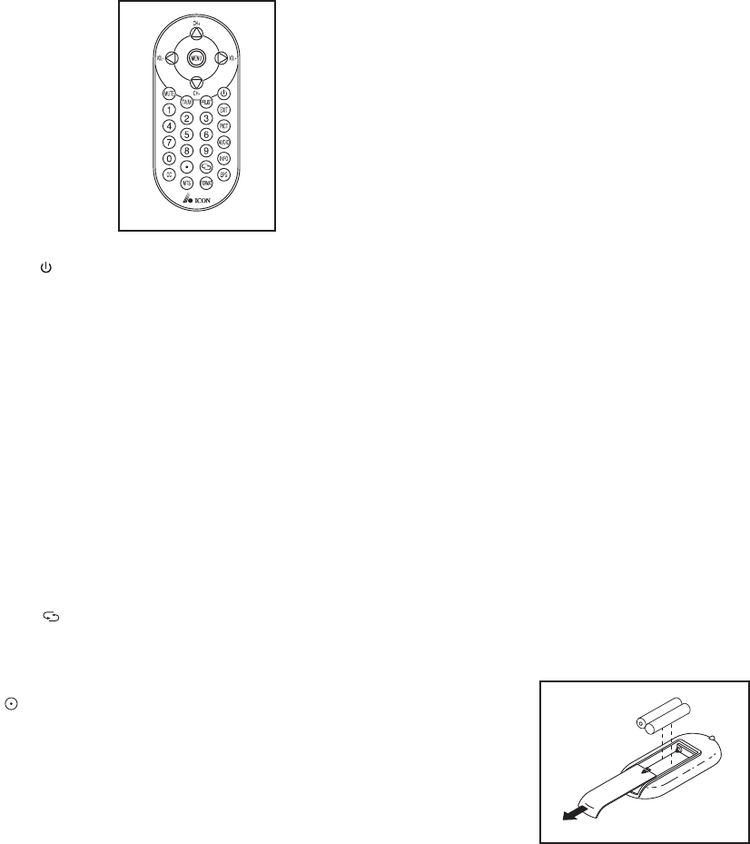
HOW TO USE THE REMOTE CONTROL
The first time you use the re-
mote control, insert batteries
(see HOW TO REPLACE THE
BATTERIES IN THE REMOTE
CONTROL at the right).
Next, stand on the treadmill and
hold the remote control near the
television. Point the remote con-
trol directly at the television.
Press the Power button ( ). After a few moments, the
television will turn on or turn off.
Press the Volume (VOL) increase or decrease button
to navigate left or right in a menu. For best results,
change the volume by pressing the Volume buttons on
the console only.
Press the Mute button to turn on or turn off the sound.
Press the numbered channel buttons or the Channel
(CH) increase or decrease button to select a channel.
The Channel increase and decrease buttons on the re-
mote also function as the up and down navigation but-
tons in a menu.
Press the Return button ( ) to view the previous
channel.
To select a subchannel, select a channel, press the
Subchannel button ( ), and then press the numbered
channel buttons.
Press the Menu button to view the main menu or to
view a previous menu. See pages 23 and 24 for infor-
mation on the menu.
Press the Exit button to exit any menu.
Press the PRLIST button to view a list of channels. If
you have labeled any channels, the menu will also
show the channel label. See page 24 for information
on labeling channels. Note: You can also view this list
by pressing the OK/Auto button on the console.
Press the EPG button to view the electronic program
guide. Note: The electronic program guide is only
available when viewing ATSC digital television.
Press the Info button to view information about the cur-
rent program and the broadcast or cable signal.
Press the CC button repeatedly to turn on or turn off
closed captioning. See step 5 on page 23 to adjust
closed captioning settings.
Press the TV/AV button repeatedly to select the televi-
sion source. See step 3 on page 21.
Press the MTS button repeatedly to select mono,
stereo, or SAP (secondary audio programming) as the
audio setting.
Press the Format button repeatedly to select auto, 4:3,
or wide image as the display format. Note: The auto
display format is only available when viewing ATSC
digital television.
Press the Pict button repeatedly to select standard, dy-
namic, soft, or personal as the image mode.
Press the Audio button repeatedly to select standard,
music, movie, or personal as the audio mode.
HOW TO REPLACE THE BATTERIES IN THE
REMOTE CONTROL
To replace the batteries,
first locate the battery
cover on the back of the
remote control. Push
down lightly on the bat-
tery cover with your
thumb and slide off the
battery cover.
Next, remove the old batteries from the remote control,
and insert two new “AAA” batteries. Make sure to in-
sert the batteries as shown in the drawing. Then,
slide the battery cover onto the remote control.
23
HOW TO ADJUST THE TELEVISION SETTINGS
You must use your remote control to adjust television
settings. Press the Menu button to enter the main
menu or to return to a previous menu. Press the Exit
button to exit a menu. Press the Channel (CH) in-
crease and decrease buttons to navigate up and down
in a menu and the Volume (VOL) increase and de-
crease buttons on your remote control to navigate right
and left.
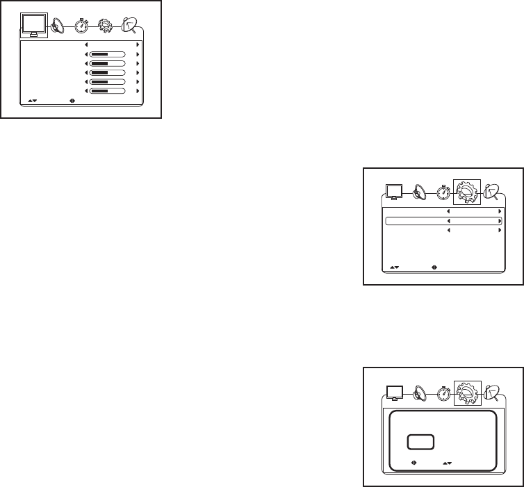
1. Enter the main menu.
Press the Menu but-
ton to enter the main
menu. To select one
of the icons across
the top of the
screen, press the
Volume increase
and decrease but-
tons on your remote
control until the desired icon appears larger than
the others. Select the monitor to adjust the image
settings. Select the speaker to adjust the audio set-
tings. Select the clock to adjust the time settings.
Select the gear to adjust the television settings.
Select the antenna to locate and save channels.
To return to the main menu, press the Menu button
repeatedly.
2. Adjust the image settings.
Select the personal, standard, dynamic, or soft pic-
ture mode. The contrast, brightness, color, sharp-
ness, and tint will automatically adjust. You can
also manually adjust the contrast, brightness,
color, sharpness, or tint.
3. Adjust the audio settings.
Select the personal, standard, movie, or music
sound mode. The bass, treble, and balance will au-
tomatically adjust. You can also manually adjust
the bass, treble, balance, or audio language.
Select an audio language to hear programs in the
selected language. Note: The audio language set-
ting will function only if another audio signal is
available.
4. Adjust the time settings.
Adjust the OSD (on-screen display) duration, sleep
timer, time zone, or daylight savings time settings.
The clock will display the current date and time and
is reset every time the power is turned on. The
OSD duration is the length of time indicators (like
channel number or the electronic program guide)
will remain on the screen after they appear. If you
set the sleep timer, the television will turn off after
the indicated number of minutes. A countdown will
warn you when the television is about to turn off.
Note: The time zone setting, daylight savings time
setting, and clock are only available when viewing
digital television.
5. Adjust the television settings.
Adjust the language used in the menus, the trans-
parency of the menu, the color mode, or the closed
caption settings. You can also restore the original
television settings.
To enter the closed
caption submenu,
highlight CLOSED
CAPTION and press
the Volume increase
button on your re-
mote control. In the
closed caption sub-
menu, adjust the
closed caption mode, the basic selection, and the
advanced selection.
When you highlight
RESTORE SETTING
and press the
Volume increase but-
ton, a confirmation
request will appear in
the display. Use the
Volume increase or
decrease button to
select YES or NO and press the Channel increase
or decrease button to confirm your selection.
Select YES to restore the original television set-
tings or NO to keep the current settings.
Picture Mode
Contrast
Brightness
Color
Sharpness
Tint
Personal
50
50
50
50
0
UP/DOWN ADJUST "MENU": EXIT
4
CCMode Off
UP/DOWN ADJUST "MENU": EXIT
Basic Selection
Advance Selection
CC1
Service 1
SELECT
Are you sure?
NO
CONFIRM
YES
24
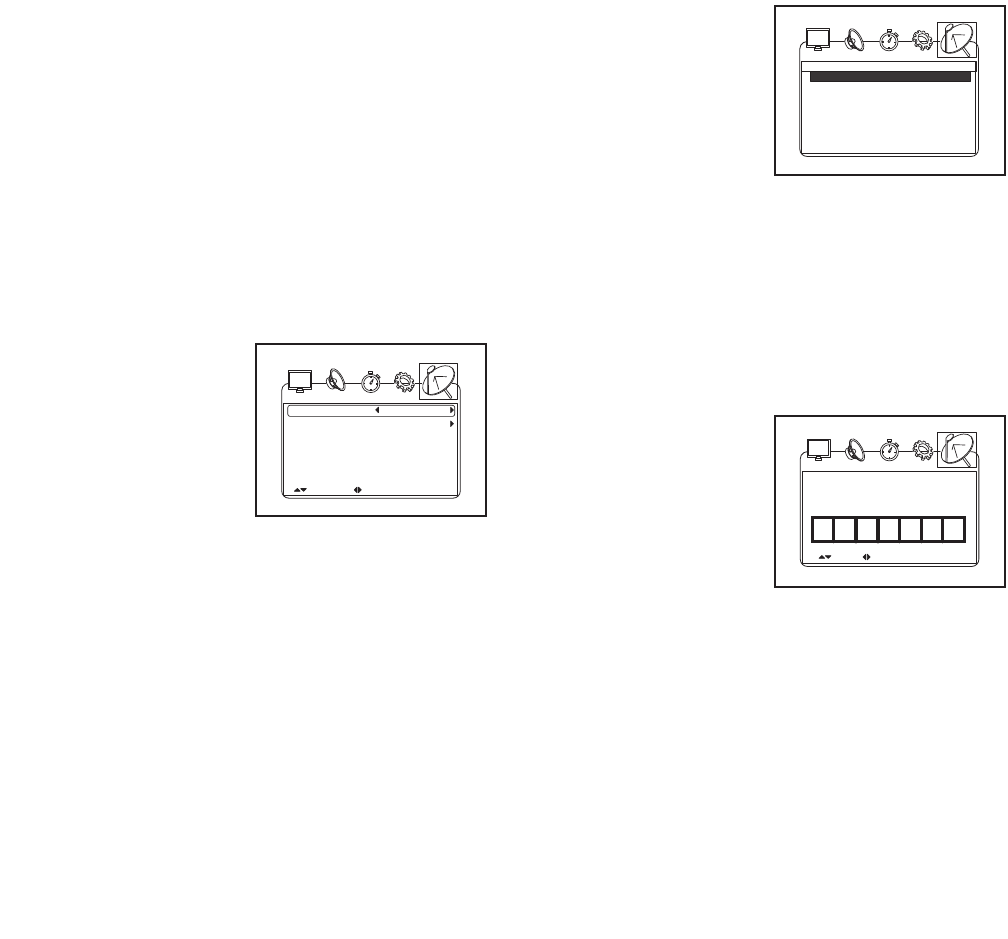
6. Scan and save channels.
Select an antenna setting. Select CATV to receive
channels through the 75 ohm terminal on the
treadmill. Select AIR to receive channels through
an antenna.
To scan for available channels, highlight AUTO
SCAN or AUTO SCAN ADD CH. To scan all chan-
nels, select the Auto scan option. To scan all chan-
nels and add an extra channel, select the Auto
Scan Add Ch option. The scan channel submenu
will appear.
If you are receiving
channels through a
CATV cable, high-
light CABLE SYS-
TEM and select the
auto, STD, IRC, or
HRC setting. Try all
four cable settings, if
necessary, to find
the optimal setting.
Highlight START TO SCAN and press the Volume
increase button to start the auto scan. The televi-
sion will begin scanning all of the channels avail-
able in your area. When no signal is detected on a
channel, the channel will be skipped. When a sig-
nal is detected, the channel will be saved into
memory and the next channel will be selected. This
process will continue until the highest channel is
reached. The television will renumber the channels
in the order in which it locates them. Do not re-
move the key while the television is scanning
channels. Note: If a television channel disappears,
scan for channels again.
After all valid chan-
nels available in your
area have been
saved into the televi-
sionʼs memory, you
can manually skip
unwanted channels.
To skip a channel,
highlight CHANNEL
SKIP and press the Volume increase button on
your remote control. In the channel skip submenu,
press the Channel increase and decrease buttons
to highlight the desired channel and the Volume in-
crease and decrease buttons to turn on or turn off
the skip option. Continue this process until you
have skipped all unwanted channels.
To change the dis-
play name of a chan-
nel, highlight CHAN-
NEL NO. and select
a channel. Then,
highlight CHANNEL
LABEL and press the
Volume increase but-
ton to enter the
channel label submenu. Press the Volume in-
crease and decrease buttons to select a number or
letter box. Then press the Channel increase and
decrease buttons to select the desired number or
letter.
7. Exit the Menu.
When you have finished adjusting the settings,
press the Exit button.
No.
"MENU": EXIT
"ENTER": SELECT
Program Name Skip
4-1 FD 3803 Off
9-2 KQUED-SD Off
EDIT SELECT "MENU": EXIT
FD 38 30
Cable System
UP/DOWN ADJUST "MENU": EXIT
Start to Scan
AUTO
25
THE INFORMATION MODE
The console features an information mode that keeps
track of the total distance that the walking belt has
moved and the total number of hours that the treadmill
has been used. The information mode also allows you
to select miles or kilometers to measure distance, and
to turn on and turn off the display demo mode.
To select the information mode, hold down the Stop
button while inserting the key into the console and then
release the Stop button. When the information mode is
selected, the following information will be shown:
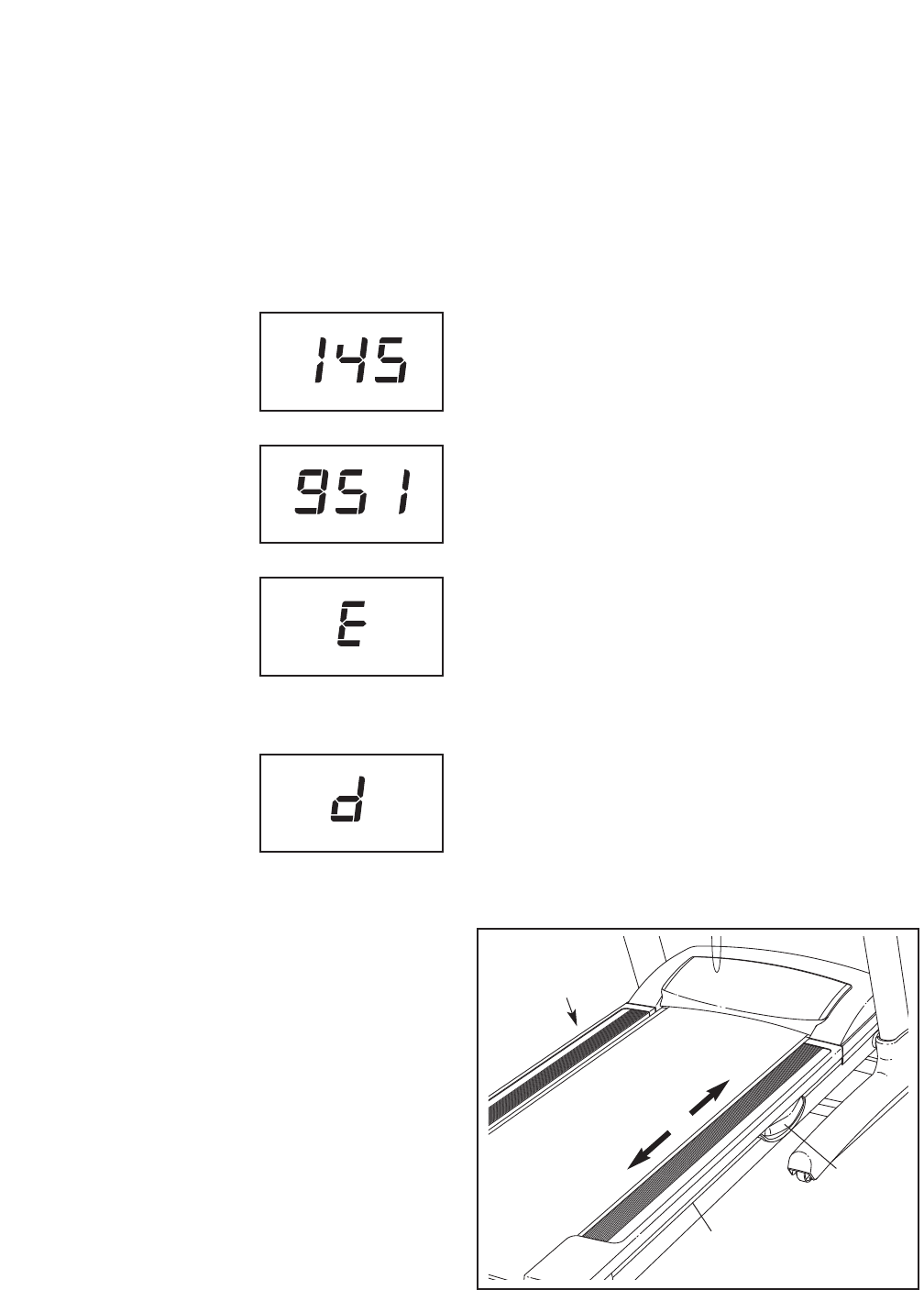
The Time display will show
the total number of hours the
treadmill has been used.
The Distance/Incline display
will show the total number of
miles or kilometers that the
walking belt has moved.
An “E” for English miles or an
“M” for metric kilometers will
appear in the Calorie/Pulse
display. Press the Speed in-
crease button to change the
unit of measurement if de-
sired.
The console features a dis-
play demo mode, designed
to be used if the treadmill is
displayed in a store. While
the demo mode is turned on,
the console will function nor-
mally when you plug in the power cord, switch the
reset/off circuit breaker to the reset position, and insert
the key into the console. However, when you remove
the key, the displays will remain lit, although the but-
tons will not function. If the demo mode is turned on, a
“d” will appear in the Speed display while the informa-
tion mode is selected. To turn on or turn off the demo
mode, press the Speed decrease button.
To exit the information mode, remove the key from the
console.
HOW TO USE THE STEREO SOUND SYSTEM
To play music or audio books through the consoleʼs
stereo sound system, you must connect your MP3
player, CD player, or other personal audio player to the
console through the audio jack above the speakers.
To use the audio jack, locate the audio wire and plug it
into the audio jack. Then plug the audio wire into a jack
on your MP3 player, CD player, or other personal
audio player. Make sure that the audio wire is fully
plugged in. While the audio wire is plugged in, the
television audio will not function.
Next, press the Play button on your MP3 player, CD
player, or other personal audio player. Adjust the vol-
ume on your personal audio player or press the Volume
increase and decrease buttons on the console.
To use earphones or headphones (not included), plug
them into the headphone jack near the Stop button on
the console.
If you are using a personal CD player and the CD
skips, set the CD player on the floor or another flat sur-
face and not on the console.
HOW TO ADJUST THE CUSHIONING SYSTEM
Remove the key from the console and unplug the
power cord. The treadmill features a cushioning sys-
tem that reduces the impact as you walk or run on the
treadmill. To increase the firmness of the walking plat-
form, step off the treadmill and slide the platform cush-
ions toward the front of the treadmill. To decrease the
firmness, slide the platform cushions toward the back
of the treadmill. Note: Make sure that both cushions
are set at the same firmness level. The faster you
run on the treadmill, or the more you weigh, the
firmer the walking platform should be.
Platform
Cushion
Walking Platform
Increase
Decrease
Platform
Cushion
HOW TO FOLD AND MOVE THE TREADMILL
HOW TO FOLD THE TREADMILL FOR STORAGE
Before folding the treadmill, adjust the incline to the
lowest position. If you do not do this, you may damage
the treadmill when you fold it. Remove the key and unplug
the power cord. CAUTION: You must be able to safely lift
45 lbs. (20 kg) to raise, lower, or move the treadmill.
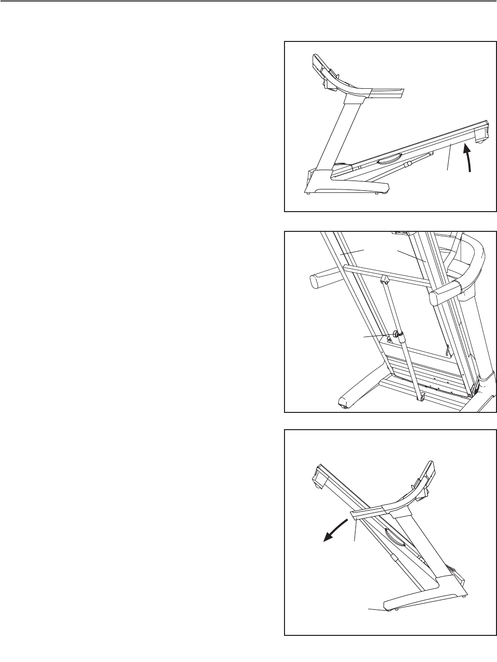
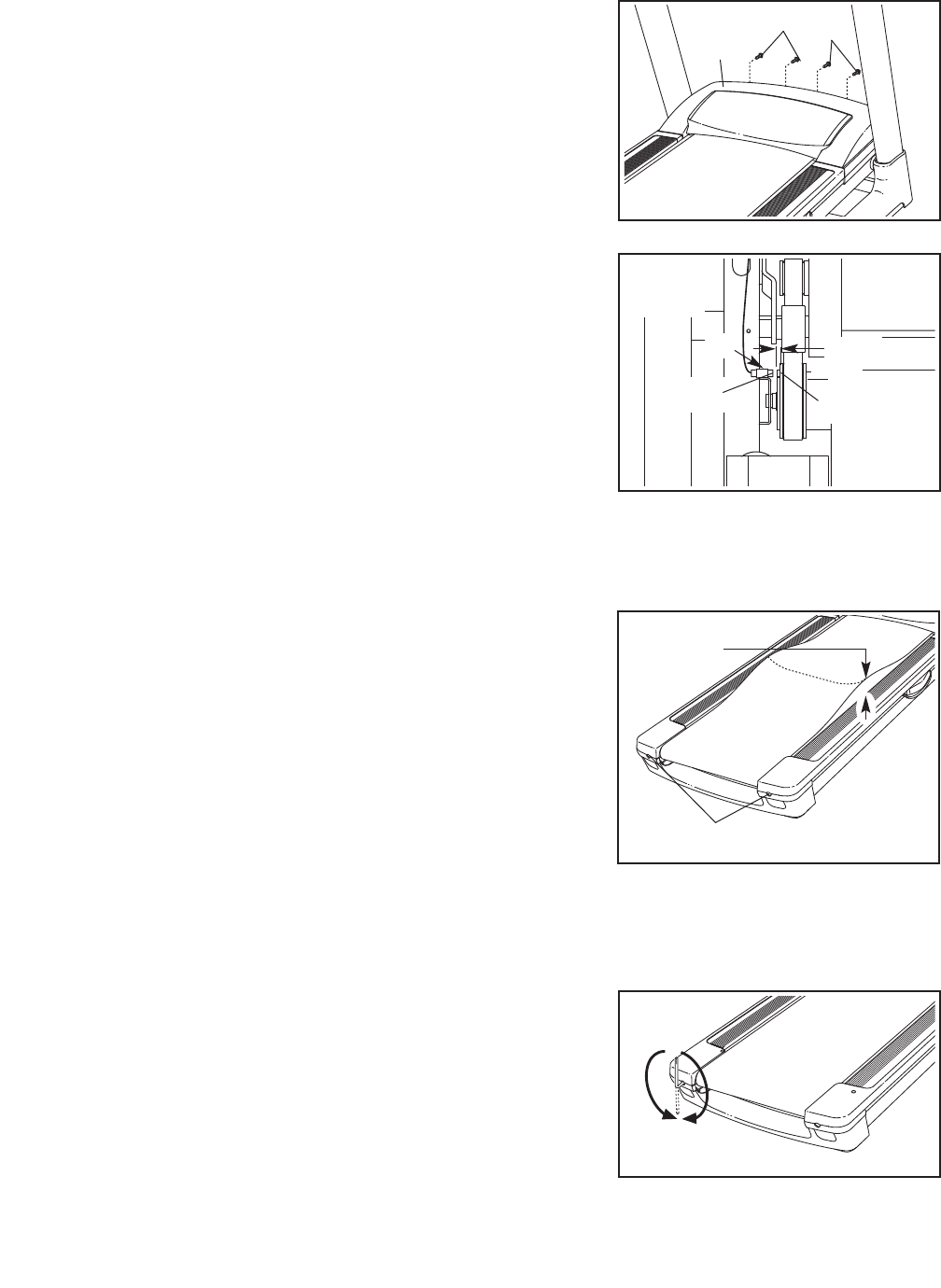
1. Hold the metal frame firmly in the location shown by
the arrow at the right. CAUTION: To decrease the pos-
sibility of injury, do not lift the frame by the plastic foot
rails. To raise the frame, bend your legs, keep your
back straight, and lift with your legs. Raise the frame
about halfway to the vertical position.
2. Raise the frame until the latch knob locks into the storage
position. Make sure that the latch knob is locked in the
storage position.
To protect the floor or carpet from damage, place a
mat under the treadmill. Keep the treadmill out of di-
rect sunlight. Do not leave the treadmill in the storage
position in temperatures above 85° F (30° C).
HOW TO MOVE THE TREADMILL
Before moving the treadmill, convert the treadmill to the stor-
age position as described above. Make sure that the latch
knob is locked in the storage position.
1. Hold the handrails and place one foot against one of the
wheels.
2. Tip the treadmill back until it rolls freely on the wheels.
Carefully move the treadmill to the desired location.
Never move the treadmill without tipping it back. To
reduce the risk of injury, use extreme caution while
moving the treadmill. Do not attempt to move the
treadmill over an uneven surface.
3. Place one foot against one of the wheels, and carefully
lower the treadmill until it is resting in the storage position.
Wheel
Handrails
Frame
Latch Knob
Frame
26
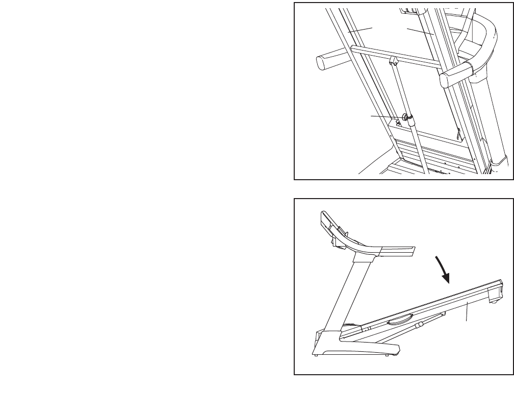
HOW TO LOWER THE TREADMILL FOR USE
1. Hold the upper end of the treadmill with your left hand.
Pull the latch knob to the left and hold it. Pivot the frame
downward and release the latch knob. Note: To release
the latch knob, it may be necessary to push the frame for-
ward as you pull the latch knob to the left.
2. Hold the metal frame firmly with both hands, and lower
it to the floor. CAUTION: To decrease the possibility of
injury, do not lower the frame by gripping only the
plastic foot rails. Do not drop the frame to the floor.
Make sure to bend your legs and keep your back
straight.
Frame
27
Latch Knob
Frame
28
TROUBLESHOOTING
Most treadmill problems can be solved by following the steps below. Find the problem that applies, and
follow the steps listed. If further assistance is needed, please see the front cover of this manual.
PROBLEM: The power does not turn on
SOLUTION: a. Make sure that the power cord is plugged into a surge suppressor, and that the surge suppressor
is plugged into a properly grounded outlet (see page 14). Use only a single-outlet surge suppres-
sor that meets all of the specifications described on page 14. IMPORTANT: The treadmill is not
compatible with GFCI-equipped outlets.
b. After the power cord has been plugged in, make sure that the key is inserted into the console.
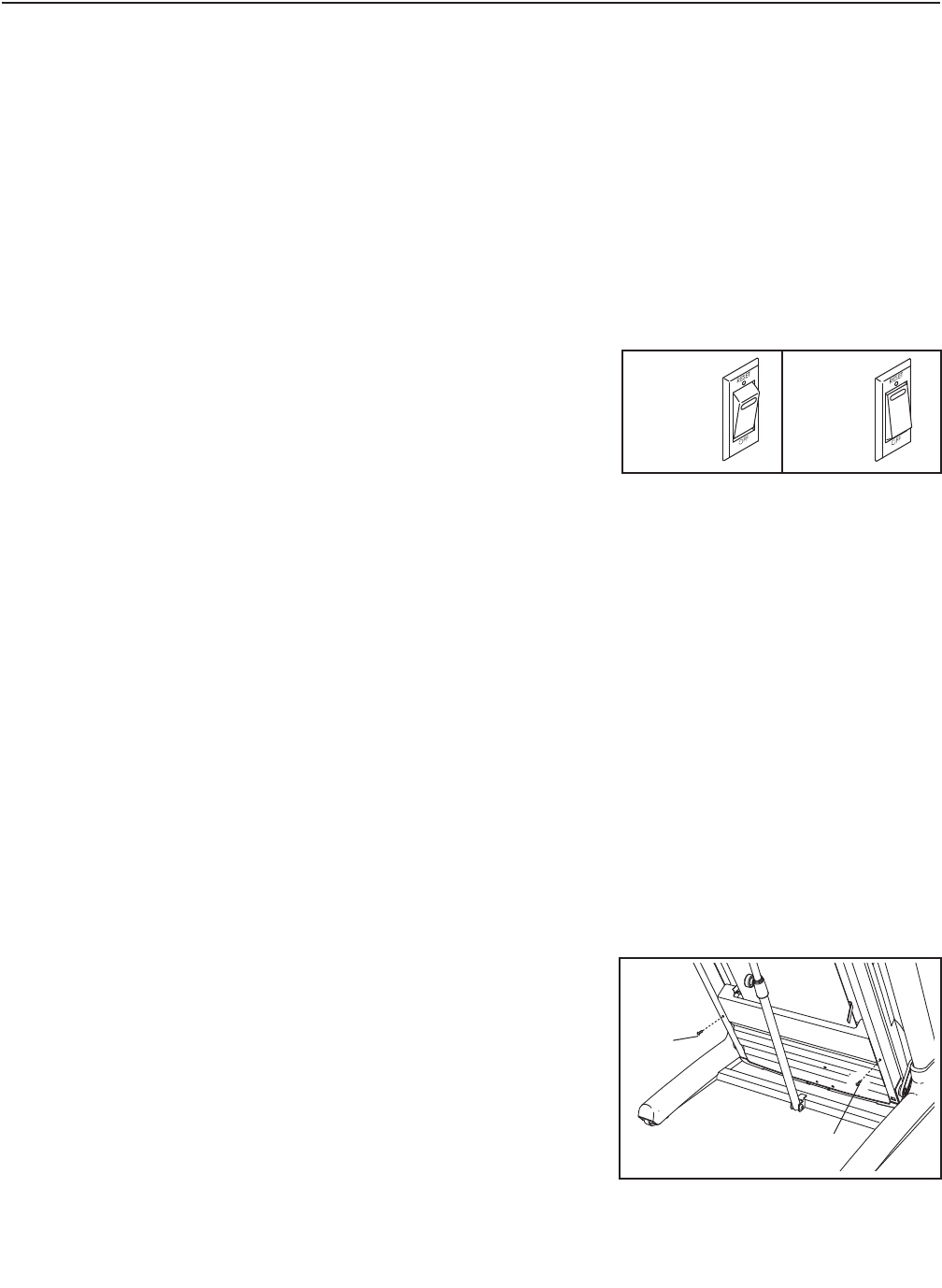
c. Check the reset/off circuit breaker located on the
treadmill frame near the power cord. If the switch pro-
trudes as shown, the circuit breaker has tripped. To
reset the circuit breaker, wait for five minutes and
then press the switch to the reset position.
PROBLEM: The power turns off during use
SOLUTION: a. Check the reset/off circuit breaker (see the drawing above). If the circuit breaker has tripped, wait
for five minutes and then press the switch to the reset position.
b. Make sure that the power cord is plugged in. If the power cord is plugged in, unplug it, wait for five
minutes, and then plug it back in.
c. Remove the key from the console. Reinsert the key into the console.
d. If the treadmill still will not run, please see the front cover of this manual.
PROBLEM: The console displays remain lit when you remove the key from the console
SOLUTION: a. The console features a display demo mode, designed to be used if the treadmill is displayed in a
store. If the displays remain lit when you remove the key, the demo mode is turned on. To turn off
the demo mode, hold down the Stop button for a few seconds. If the displays are still lit, see THE
INFORMATION MODE on page 25 to turn off the demo mode.
PROBLEM: The displays of the console do not function properly
SOLUTION: a. Remove the key from the console and UNPLUG THE
POWER CORD. Place the treadmill in the storage po-
sition (see HOW TO FOLD THE TREADMILL FOR
STORAGE on page 26).
Next, remove the two indicated #8 x 3/4" Screws (1).
Tripped Reset
c
a
1
1
29
Lower the treadmill (see HOW TO LOWER THE
TREADMILL FOR USE on page 27). Remove the four
indicated #8 x 3/4" Screws (1), and remove the Motor
Hood (75).
Next, locate the Reed Switch (53) and the Magnet
(58) on the left side of the Pulley (59). Turn the Pulley
until the Magnet is aligned with the Reed Switch.
Make sure that the gap between the Magnet and
the Reed Switch is about 1/8 in. (3 mm). If neces-
sary, loosen the indicated #8 x 3/4" Tek Screw (24),
move the Reed Switch slightly, and then retighten the
Screw. Then, reattach the Hood (not shown) with the
six #8 x 3/4" Screws (not shown), and run the tread-
mill for a few minutes to check for a correct speed
reading.
PROBLEM: The walking belt slows when walked on
SOLUTION: a. Use only a single-outlet surge suppressor that meets all of the specifications described on page 14.
b. If the walking belt is overtightened, treadmill perfor-
mance may decrease and the walking belt may be-
come damaged. Remove the key and UNPLUG THE
POWER CORD. Using the hex key, turn both idler
roller bolts counterclockwise, 1/4 of a turn. When the
walking belt is properly tightened, you should be able
to lift each edge of the walking belt 3 to 4 in. (8 to 10
cm) off the walking platform. Be careful to keep the
walking belt centered. Then, plug in the power cord,
insert the key, and run the treadmill for a few min-
utes. Repeat until the walking belt is properly tight-
ened.
c. If the walking belt still slows when walked on, please see the front cover of this manual.
PROBLEM: The walking belt is off-center or slips when walked on
SOLUTION: a. If the walking belt is off-center, remove the key and
UNPLUG THE POWER CORD. If the walking belt
has shifted to the left, use the hex key to turn the
left idler roller bolt clockwise 1/2 of a turn; if the
walking belt has shifted to the right, turn the left
idler roller bolt counterclockwise 1/2 of a turn. Be
careful not to overtighten the walking belt. Plug in the
power cord, insert the key, and run the treadmill for a
few minutes. Repeat until the walking belt is cen-
tered.
Top
View
24
53
1/8 in.
59
58
1
75
1
Idler Roller Bolts
b
3–4 in.
a

30
b. If the walking belt slips when walked on, first remove
the key and UNPLUG THE POWER CORD. Using
the hex key, turn both idler roller bolts clockwise, 1/4
of a turn. When the walking belt is correctly tight-
ened, you should be able to lift each edge of the
walking belt 3 to 4 in. (8 to 10 cm) off the walking
platform. Be careful to keep the walking belt cen-
tered. Then, plug in the power cord, insert the key,
and carefully walk on the treadmill for a few minutes.
Repeat until the walking belt is properly tightened.
PROBLEM: The incline of the treadmill does not change correctly
SOLUTION: a. With the key in the console, press one of the Incline buttons. While the incline is changing, re-
move the key. After a few seconds, re-insert the key. The treadmill will automatically rise to the
maximum incline level and then return to the minimum level. This will recalibrate the incline system.
PROBLEM: Television reception is poor
SOLUTION: a. Make sure that the television settings are set correctly. See HOW TO ADJUST THE TELEVISION
SETTINGS on page 23.
b. For the digital television to operate properly, good reception is necessary. If you are using an an-
tenna, make sure that it is properly connected and adjusted for optimal reception. (See HOW TO
CONNECT AN ANTENNA on page 13.)
c. Check for the problems listed below and follow the applicable instructions.
• Ignition (black spots or horizontal streaks that appear or a picture that flutters or drifts)—
Usually this is caused by interference from automobile ignition systems, neon lamps, electric
drifts, or other electric appliances. Try changing the position of the treadmill or other electric
appliances to correct the problem.
• Ghosts—Ghosts are caused by the television signal following two paths—one is the direct path
and the other is reflected from tall buildings, hills, or other objects. Change the direction or po-
sition of the antenna to improve reception.
• Blue Screen—If the treadmill is located in the fringe area of a television station where the sig-
nal is weak, the picture may be of poor quality or a blue screen may appear. If the signal is
weak, it may be necessary to install an external antenna to improve the picture.
• Fading—If blocks of the picture are missing, the picture moves around the screen, or the pic-
ture disappears, the signal may be weak. Change the direction or position of the antenna to im-
prove reception. Make sure the television settings are set correctly (see HOW TO ADJUST
TELEVISION SETTINGS on page 23). Do not use a splitter.
Note: If one of these problems appears when the cable from a CATV company is connected, the
problem may be caused by the cable company broadcast.
b

31
PROBLEM: The
remote control
does not function correctly
SOLUTION: a.
Make sure you are standing on the treadmill, holding the remote control near the television and
pointing the remote control directly at the console.
b. If your remote control is still not functioning correctly,
the batteries should be replaced; most re-
mote control problems are the result of low batteries. See page 22 to replace the batteries.
PROBLEM: The television is not receiving a signal
SOLUTION: a. Make sure the correct TV or AV source is selected. See step 3 on page 21 to select a television
source.
b. Make sure that the antenna, CATV cable, or AV wire is connected securely to the treadmill. See
page 13 to connect a cable to treadmill.
c. Scan for broadcast or cable signals. See page 24 to scan for signals.
d. Due to an FCC requirement, analog signals may no longer be broadcast over the air after June
12, 2009. If you wish to view television signals through an antenna after that date, you must have
an antenna capable of receiving digital signals or a digital converter box. Cable television will not
be affected.
PROBLEM: The
volume is too loud or the television audio makes a crackling sound
SOLUTION: a.
If the television audio makes a crackling sound when the volume is turned up, the volume is too
loud. Press the Volume increase or decrease button on the remote control until the volume level is
80 percent. Once the volume reaches 80 percent, adjust the volume by pressing the Volume but-
tons on the console only.
PROBLEM: The
volume cannot be turned up
SOLUTION: a.
If the volume cannot be turned up, the volume may have been adjusted with the remote control.
Press the Volume increase or decrease button on the remote control until the volume level is 80
percent. Once the volume reaches 80 percent, adjust the volume by pressing the Volume buttons
on the console only.
b. If there is no sound coming from the television, make sure the television audio is not muted.
c. If there is no sound coming from the television, make sure the audio wire is not plugged into the
audio jack on the console.
PROBLEM: The television needs to be cleaned
SOLUTION: a. UNPLUG THE POWER CORD. To clean the television, wipe the television and screen using a
soft cloth with a small amount of soft detergent. Do not use a polishing cloth, solvent, or any
type of propellant or chemical detergent such as alcohol or benzene.
32
These guidelines will help you to plan your exercise
program. For detailed exercise information, obtain a
reputable book or consult your physician. Remember,
proper nutrition and adequate rest are essential for
successful results.
EXERCISE INTENSITY
Whether your goal is to burn fat or to strengthen your
cardiovascular system, exercising at the proper inten-
sity is the key to achieving results. You can use your
heart rate as a guide to find the proper intensity level.
The chart below shows recommended heart rates for
fat burning and aerobic exercise.
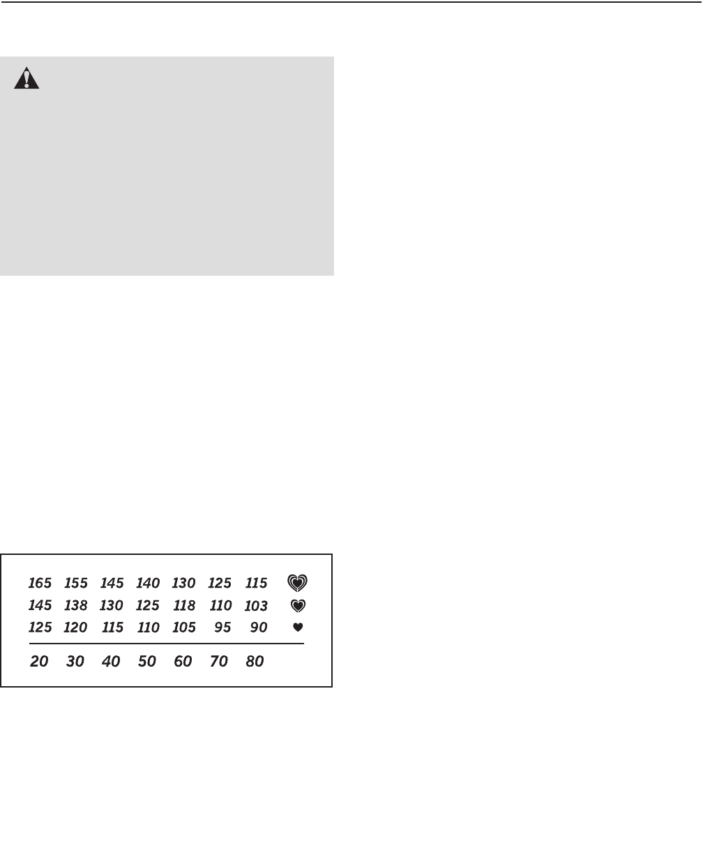
To find the proper intensity level, find your age at the
bottom of the chart (ages are rounded off to the near-
est ten years). The three numbers listed above your
age define your “training zone.” The lowest number is
the heart rate for fat burning, the middle number is the
heart rate for maximum fat burning, and the highest
number is the heart rate for aerobic exercise.
Burning Fat—To burn fat effectively, you must exer-
cise at a low intensity level for a sustained period of
time. During the first few minutes of exercise, your
body uses carbohydrate calories for energy. Only after
the first few minutes of exercise does your body begin
to use stored fat calories for energy. If your goal is to
burn fat, adjust the intensity of your exercise until your
heart rate is near the lowest number in your training
zone. For maximum fat burning, exercise with your
heart rate near the middle number in your training
zone.
Aerobic Exercise—If your goal is to strengthen your
cardiovascular system, you must perform aerobic exer-
cise, which is activity that requires large amounts of
oxygen for prolonged periods of time. For aerobic ex-
ercise, adjust the intensity of your exercise until your
heart rate is near the highest number in your training
zone.
WORKOUT GUIDELINES
Warming Up—Start with 5 to 10 minutes of stretching
and light exercise. A warm-up increases your body
temperature, heart rate, and circulation in preparation
for exercise.
Training Zone Exercise—Exercise for 20 to 30 min-
utes with your heart rate in your training zone. (During
the first few weeks of your exercise program, do not
keep your heart rate in your training zone for longer
than 20 minutes.) Breathe regularly and deeply as you
exercise–never hold your breath.
Cooling Down—Finish with 5 to 10 minutes of stretch-
ing. Stretching increases the flexibility of your muscles
and helps to prevent post-exercise problems.
EXERCISE FREQUENCY
To maintain or improve your condition, complete three
workouts each week, with at least one day of rest be-
tween workouts. After a few months of regular exer-
cise, you may complete up to five workouts each
week, if desired. Remember, the key to success is to
make exercise a regular and enjoyable part of your
everyday life.
EXERCISE GUIDELINES
WARNING: Before beginning any
exercise program, consult your physician.
This is especially important for persons over
age 35 or persons with pre-existing health
problems.
The pulse sensor is not a medical device.
Various factors may affect the accuracy of
heart rate readings. The pulse sensor is in-
tended only as an exercise aid in determining
heart rate trends in general.

33
PART LIST—Model No. HRTL19509.0 R1009A
To locate the parts listed below, see the EXPLODED DRAWING near the end of this manual.
Key No. Qty. Description Key No. Qty. Description
1 56 #8 x 3/4" Screw
263/8" x 1 1/4" Patch Bolt
313/8" x 1 3/4" Bolt
413/8" x 2" Bolt
543/8" x 3 3/4" Patch Bolt
6 10 3/8" Star Washer
783/8" Jam Nut
82#8 x 1" Screw
92#8 x 1/2" Screw
10 2 Drive Motor Bolt
11 1 3/8" x 1 3/4" Hex Head Bolt
12 16 #8 x 3/4" Flat Head Screw
13 1 3/8" x 2" Hex Head Bolt
14 8 #8 Belt Guide Screw
15 2 1/4" x 2 1/2" Bolt
16 16 #8 x 1/2" Screw
17 2 1/4" x 1 1/4" Bolt
18 2 5/16" x 1 1/4" Bolt
19 12 #12 x 1" Screw
20 2 3/8" x 3/4" Bolt
21 2 3/8" x 1 3/4" Bolt
22 2 3/8" x 2 3/8" Bolt
23 7 #8 x 1/2" Washer Head Screw
24 15 #8 x 3/4" Tek Screw
25 4 #8 x 1" Screw
26 8 #8 x 3/4" Pan Head Tek Screw
27 4 #6 x 1/2" Screw
28 4 #8 Star Washer
29 4 #8 x 1" Tek Screw
30 4 1/4" Star Washer
31 1 3/8" Star Washer
32 2 1/4" Lock Washer
33 4 Base Pad Spacer
34 4 1/4" Locknut
35 1 #8 Locknut
36 2 3/8" Hex Nut
37 4 Hood Clip
38 2 5/16" Flange Nut
39 1 M12 Nut
40 4 Handrail Cover Fastener
41 1 Left Foot Insert
42 2 Rear Wheel Axle
43 4 Rear Wheel
44 4 Caution Decal
45 1 Right Foot Insert
46 1 Rear Foot
47 2 Platform Cushion
48 2 Cushion Track
49 1 Warning Decal
50 1 Walking Platform
51 2 Belt Guide
52 2 Isolator
53 1 Reed Switch
54 2 Hood Mount
55 2 Lift Arm Spacer
56 2 Lift Arm
57 2 Incline Rod Spacer
58 1 Magnet
59 1 Drive Roller/Pulley
60 1 Electronics Bracket
61 1 Controller
62 1 Front Cap
63 1 Reset/Off Circuit Breaker
64 2 Upright Wire Grommet
65 1 Power Cord Grommet
66 1 Power Cord
67 1 Frame
68 1 Walking Belt
69 1 Idler Roller
70 1 Hex Key
71 1 5/32" Hex Key
72 1 Rear Foot Insert
73 1 Reed Switch Clamp
74 1 Hood Accent
75 1 Motor Hood
76 1 Incline Rod
77 1 Incline Motor
78 1 Incline Motor Wire
79 1 Stop Bracket
80 1 Stop Bracket Spacer
81 1 Drive Motor Belt
82 1 Drive Motor
83 1 Left Rail Cover
84 1 Left Foot Rail
85 1 Right Rail Cover
86 1 Latch Cap
87 1 Storage Latch
88 1 Latch Knob
89 1 Left Upright Sleeve
90 1 Right Upright Sleeve
91 1 Left Upright
92 1 Right Upright
93 1 Upright Wire
94 1 AV Cable
95 1 TV Cable
96 1 AV Wire
97 6 Releasable Tie
98 2 Tie Clamp
99 9 Plastic Tie
100 1 Left Base Cover

34
Key No. Qty. Description Key No. Qty. Description
101 2 Wheel
102 1 Right Base Cover
103 1 Base
104 1 AV Cover
105 4 Base Pad
106 1 Static Decal
107 2 Console Ground Wire
108 1 Console Plate
109 2 Handrail Cap
110 1 Handrail
111 2 Handrail Grip
112 2 Console Clamp
113 1 Speaker Cover
114 1 Speaker
115 1 Console
116 1 Fan
117 1 TV Console
118 1 Audio Wire
119 1 Console Base
120 1 Console Wire
121 1 Right Pulse Grip
122 1 Access Door
123 1 Left Pulse Grip
124 1 Key/Clip
125 1 TV Remote
126 1 Right Foot Rail
127 2 Cushion Stop
128 1 Filter Wire
129 1 Book Rack
*–4" White Wire, M/F
*–Userʼs Manual
Note: Specifications are subject to change without notice. For information about ordering replacement parts, see
the back cover of this manual. *These parts are not illustrated.
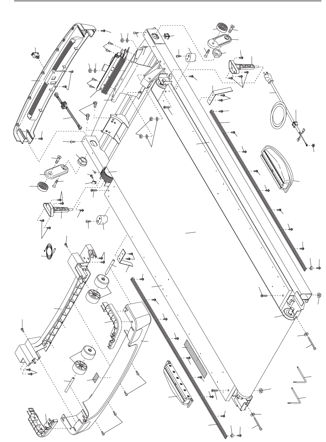
24
73
52
17
49
18
69
1
50
68
18
17
51
14
51
58
57
56
55
54
1
1
21
10
24
59
60
54
11
1
1
24
1
20
21
55
56
57
20
52
14
38
32
67
34
30
62
16
35
66
65
70
30
34
23
23
30
34
61
53 63
32
15
15
38
64
71
23
43
43
1
1
72
1
1
42
42
46
41
45
44
24
24
47
47
48
12
12
12
12
12
127
12
12
12
48 12
12
8
12
128
24
24
127
8
35
EXPLODED DRAWING A—Model No. HRTL19509.0 R1009A
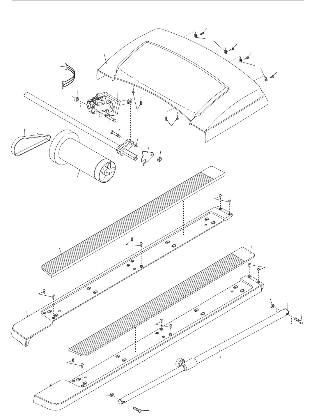
77
7
11
76
13
7
79
80
1
75
37
37
84
81
82
19
19
19
87
3
7
4
786
88
83
78
126
85
19
19
19
14
14
1
1
1
36
EXPLODED DRAWING B—Model No. HRTL19509.0 R1009A
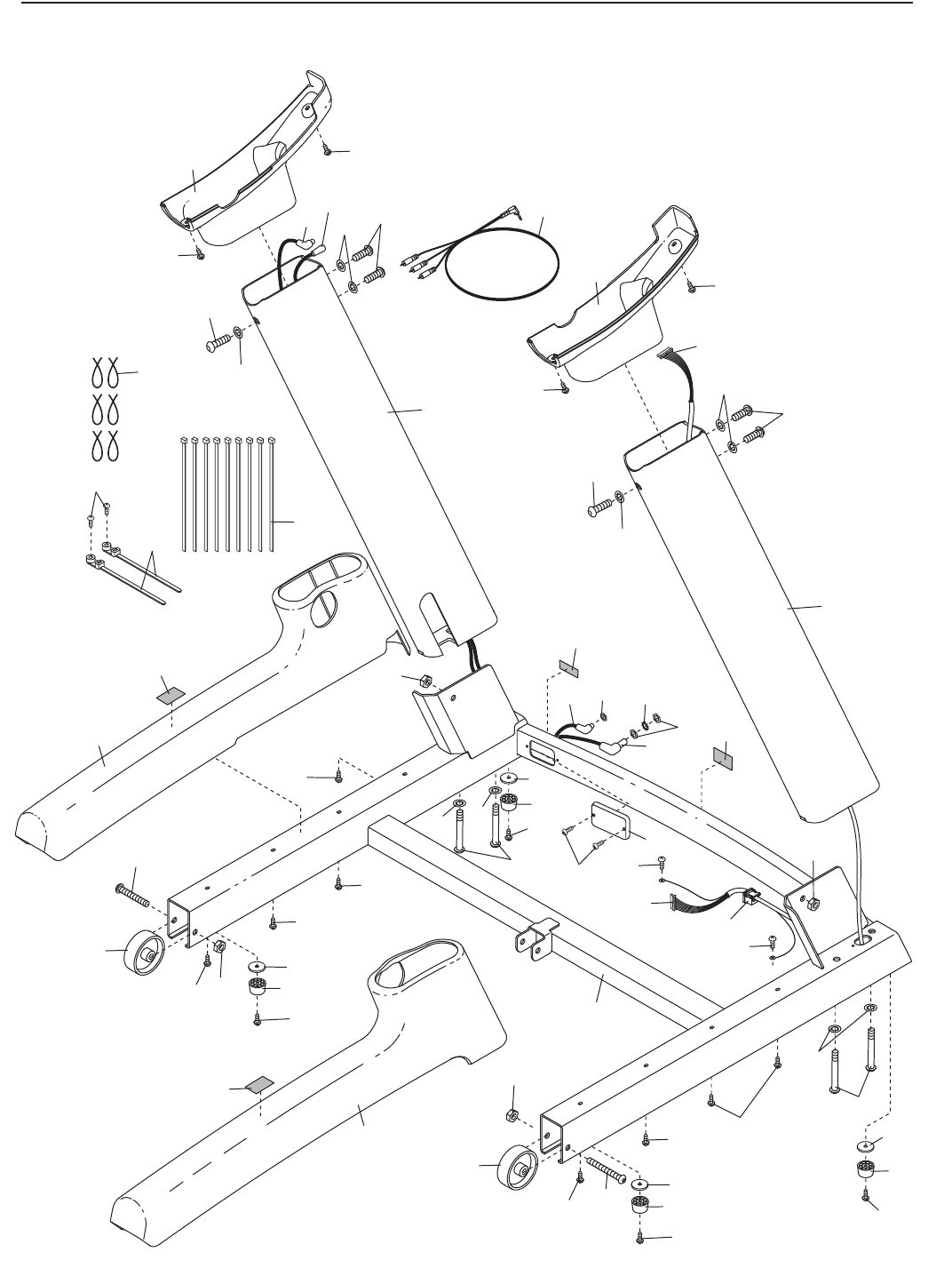
96
91
92
103
7
101
22
44
44
101
22
7
2
44
7
7
29
105
29
105
89
90
93
93
1
1
29
105
11
1
1
1
100
102
24
6
5
51
104
95
36
31
39
94
94 95
64
106
33
33
33
2
2
2
6
66
6
6
6
23
23
29
105
33
24
24
24
24
98
97
99
37
EXPLODED DRAWING C—Model No. HRTL19509.0 R1009A
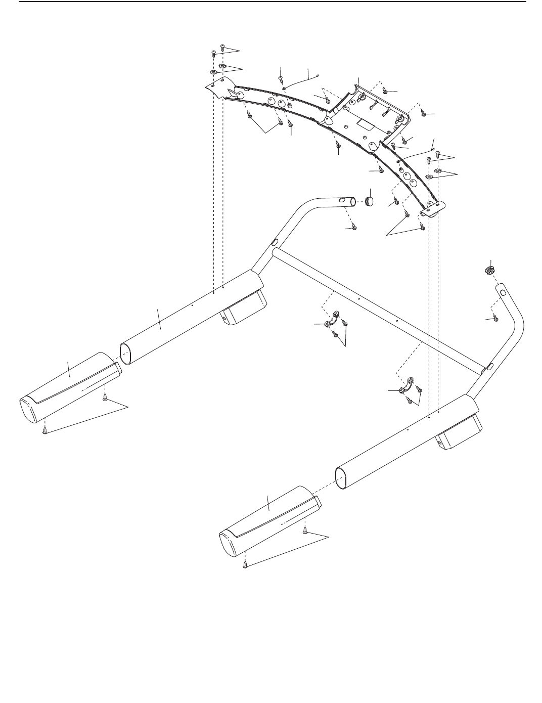
110
111
40
40
26
26
28
1
1
11
108
25
112
112
25
28 107
9
16
1
16
26
26
1
109
109
111
107
9
1
1
38
EXPLODED DRAWING D—Model No. HRTL19509.0 R1009A
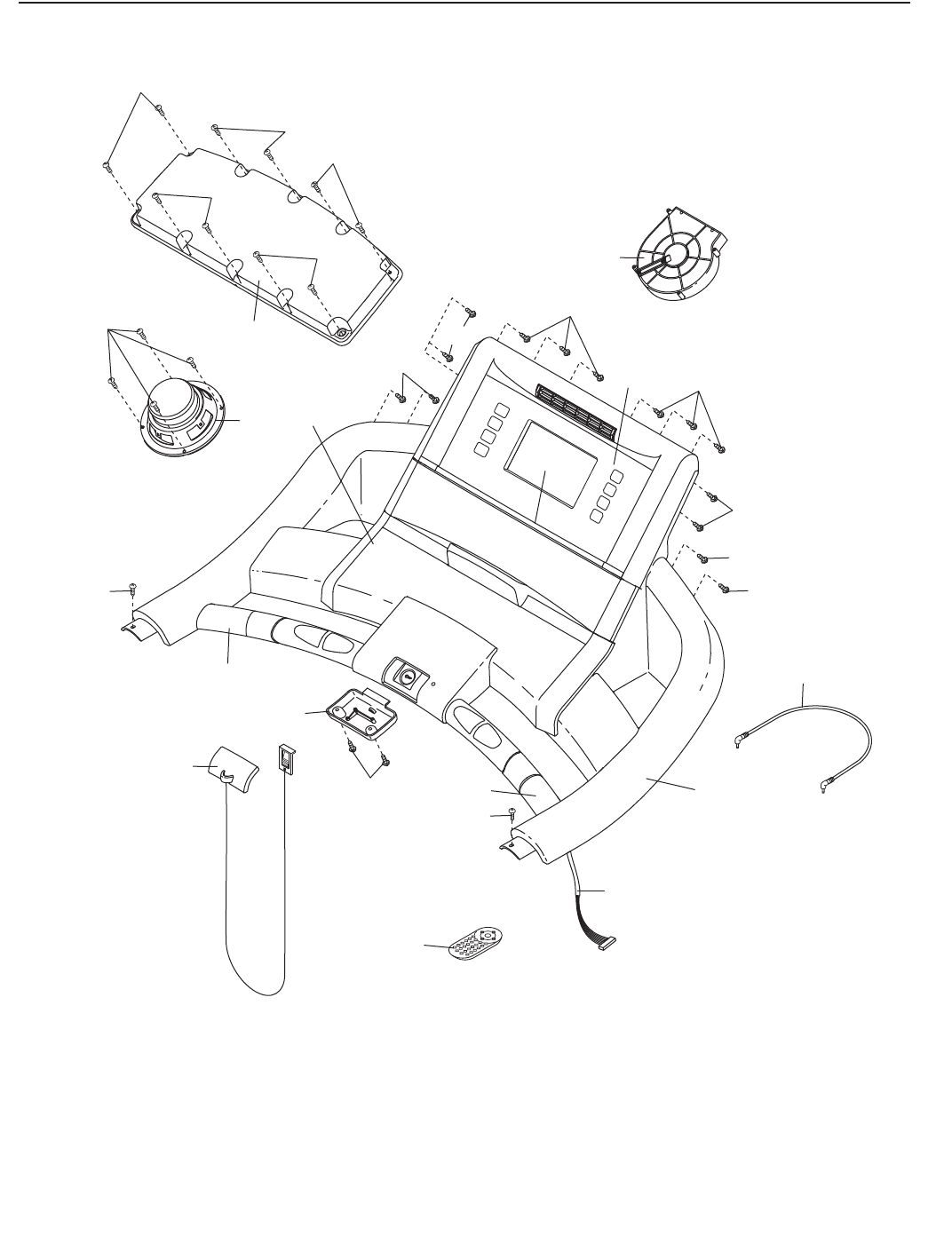
125
122
1119
117
116
26 1
1
1
123
121
115
120
124
16
113
27
1
1
114
16
16
16
16
118
26
129
1
1
39
EXPLODED DRAWING E—Model No. HRTL19509.0 R1009A

Part No. 286180 R1009A Printed in USA © 2009 ICON IP, Inc.
ORDERING REPLACEMENT PARTS
To order replacement parts, please see the front cover of this manual. To help us assist you, be prepared to
provide the following information when contacting us:
• the model number and serial number of the product (see the front cover of this manual)
• the name of the product (see the front cover of this manual)
• the key number and description of the replacement part(s) (see the PART LIST and the EXPLODED
DRAWING near the end of this manual)
ICON Health & Fitness, Inc. (ICON) warrants this product to be free from defects in workmanship and
material, under normal use and service conditions. The frame and drive motor are warranted for a life-
time. Parts and labor are warranted for one (1) year from the date of purchase.
This warranty extends only to the original purchaser. ICONʼs obligation under this warranty is limited to
repairing or replacing, at ICONʼs option, the product through one of its authorized service centers. All re-
pairs for which warranty claims are made must be preauthorized by ICON. If the product is shipped to a
service center, freight charges to and from the service center will be the customerʼs responsibility. For
replacement parts shipped while the product is under warranty, the customer will be responsible for a
minimal handling charge. For in-home service, the customer will be responsible for a minimal trip charge.
This warranty does not extend to any damage to a product caused by or attributable to freight damage,
abuse, misuse, improper or abnormal usage, or repairs not provided by an ICON authorized service cen-
ter; to products used for commercial or rental purposes or as store display models; or to products trans-
ported or purchased outside the US. No other warranty beyond that specifically set forth above is autho-
rized by ICON.
ICON is not responsible or liable for indirect, special, or consequential damages arising out of or in con-
nection with the use or performance of the product; damages with respect to any economic loss, loss of
property, loss of revenues or profits, loss of enjoyment or use, or costs of removal or installation; or other
consequential damages of whatsoever nature. Some states do not allow the exclusion or limitation of in-
cidental or consequential damages. Accordingly, the above limitation may not apply to you.
The warranty extended hereunder is in lieu of any and all other warranties, and any implied warranties of
merchantability or fitness for a particular purpose are limited in their scope and duration to the terms set
forth herein. Some states do not allow limitations on how long an implied warranty lasts. Accordingly, the
above limitation may not apply to you.
This warranty gives you specific legal rights. You may also have other rights that vary from state to state.
ICON Health & Fitness, Inc., 1500 S. 1000 W., Logan, UT 84321-9813
LIMITED WARRANTY
IMPORTANT: You must register this product within 30 days of the purchase date to avoid added
fees for service needed under warranty. Go to www.healthriderservice.com/registration.
