Healthrider T90 Users Manual
Healthrider-Hrtl13910-Owners-Manual healthrider-hrtl13910-owners-manual
2015-02-10
: Healthrider Healthrider-T90-Users-Manual-468673 healthrider-t90-users-manual-468673 healthrider pdf
Open the PDF directly: View PDF ![]() .
.
Page Count: 34
USER'S MANUAL
CAUTION
Read all precautions and instruc-
tions in this manual before using
this equipment. Save this manual
for future reference.
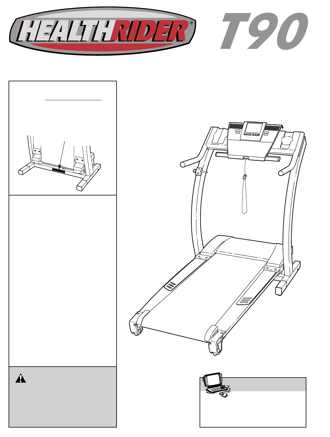
Serial Number Decal
Model No. HRTL13910
Serial No.
Find the serial number in the location
shown below. Write the serial number
in the space above for reference.
Visit our website at
www.healthrider.com
new products, prizes,
fitness tips, and much more!
QUESTIONS?
If you have questions, or if there
are missing parts, we will guar-
antee complete satisfaction
through direct assistance from
our factory.
TO AVOID UNNECESSARY
DELAYS, PLEASE CALL DIRECT
TO OUR TOLL-FREE CUSTOMER
HOT LINE. The trained techni-
cians on our customer hot line
will provide immediate assis-
tance, free of charge.
CUSTOMER HOT LINE:
1-800-999-3756
Mon.–Fri., 6 a.m.– 6 p.m. MST
Patent Pending

TABLE OF CONTENTS
IMPORTANT PRECAUTIONS . . . . . . . . . . . . . . . . . . . . . . . . . . . . . . . . . . . . . . . . . . . . . . . . . . . . . . . . . . . . . . . . .3
BEFORE YOU BEGIN . . . . . . . . . . . . . . . . . . . . . . . . . . . . . . . . . . . . . . . . . . . . . . . . . . . . . . . . . . . . . . . . . . . . . . .6
ASSEMBLY . . . . . . . . . . . . . . . . . . . . . . . . . . . . . . . . . . . . . . . . . . . . . . . . . . . . . . . . . . . . . . . . . . . . . . . . . . . . . . .7
OPERATION AND ADJUSTMENT . . . . . . . . . . . . . . . . . . . . . . . . . . . . . . . . . . . . . . . . . . . . . . . . . . . . . . . . . . . . .9
HOW TO FOLD AND MOVE THE TREADMILL . . . . . . . . . . . . . . . . . . . . . . . . . . . . . . . . . . . . . . . . . . . . . . . . . .25
TROUBLE-SHOOTING . . . . . . . . . . . . . . . . . . . . . . . . . . . . . . . . . . . . . . . . . . . . . . . . . . . . . . . . . . . . . . . . . . . . .26
CONDITIONING GUIDELINES . . . . . . . . . . . . . . . . . . . . . . . . . . . . . . . . . . . . . . . . . . . . . . . . . . . . . . . . . . . . . . .29
PART LIST . . . . . . . . . . . . . . . . . . . . . . . . . . . . . . . . . . . . . . . . . . . . . . . . . . . . . . . . . . . . . . . . . . . . . . . . . . . . . . .30
ORDERING REPLACEMENT PARTS . . . . . . . . . . . . . . . . . . . . . . . . . . . . . . . . . . . . . . . . . . . . . . . . . .Back Cover
LIMITED WARRANTY . . . . . . . . . . . . . . . . . . . . . . . . . . . . . . . . . . . . . . . . . . . . . . . . . . . . . . . . . . . . . . .Back Cover
Note: An EXPLODED DRAWING is attached in the center of this manual.
2
HealthRider is a registered trademark of ICON Health & Fitness, Inc.

1. It is the responsibility of the owner to ensure
that all users of this treadmill are adequately
informed of all warnings and precautions.
2. Use the treadmill only as described in this
manual.
3. Place the treadmill on a level surface, with at
least eight feet of clearance behind it. Do not
place the treadmill on any surface that blocks
air openings. To protect the floor or carpet
from damage, place a mat under the treadmill.
4. Keep the treadmill indoors, away from mois-
ture and dust. Do not put the treadmill in a
garage or covered patio, or near water.
5. Do not operate the treadmill where aerosol
products are used or where oxygen is being
administered.
6. Keep children under the age of 12 and pets
away from the treadmill at all times.
7. The treadmill should not be used by persons
weighing more than 250 pounds.
8. Never allow more than one person on the
treadmill at a time.
9. Wear appropriate exercise clothing when
using the treadmill. Do not wear loose cloth-
ing that could become caught in the treadmill.
Athletic support clothes are recommended
for both men and women. Always wear ath-
letic shoes. Never use the treadmill with bare
feet, wearing only stockings, or in sandals.
10. When connecting the power cord (see page 9),
plug the power cord into a surge suppressor
(not included) and plug the surge suppressor
into a grounded circuit capable of carrying 15
or more amps. No other appliance should be on
the same circuit. Do not use an extension cord.
11. Use only a single-outlet surge suppressor that
meets all of the specifications described on
page 9. To purchase a surge suppressor, see
your local HealthRider dealer or call 1-800-806-
3651 and order part number 146148.
12. Failure to use a properly functioning surge
suppressor could result in damage to the con-
trol system of the treadmill. If the control sys-
tem is damaged, the walking belt may change
speed or stop unexpectedly, which may result
in a fall and serious injury.
13. Keep the power cord and the surge suppres-
sor away from heated surfaces.
14. Never move the walking belt while the power
is turned off. Do not operate the treadmill if
the power cord or plug is damaged, or if the
treadmill is not working properly. (See
BEFORE YOU BEGIN on page 6 if the tread-
mill is not working properly.)
15. Never start the treadmill while you are stand-
ing on the walking belt. Always hold the
handrails while using the treadmill.
16. To protect the treadmill and TV during light-
ning storms, unplug the power cord from the
wall outlet and disconnect the antenna or
cable system. This will prevent damage due
to lightning and power line surges.
17. The treadmill is capable of high speeds.
Adjust the speed in small increments to avoid
sudden jumps in speed.
18. The pulse sensor is not a medical device.
Various factors, including the user's move-
ment, may affect the accuracy of heart rate
readings. The pulse sensor is intended only
as an exercise aid in determining heart rate
trends in general.
19. Never leave the treadmill unattended while it
is running. Always remove the key, unplug
the power cord, and move the on/off switch to
the off position when the treadmill is not in
use. (See the drawing on page 6 for the loca-
tion of the on/off switch.)
20. Do not attempt to raise, lower, or move the
treadmill until it is properly assembled. (See
ASSEMBLY on page 7, and HOW TO FOLD
AND MOVE THE TREADMILL on page 25.) You
must be able to safely lift 45 pounds (20 kg) in
order to raise, lower, or move the treadmill.
WARNING: To reduce the risk of burns, fire, electric shock, or injury to persons, read the
following important precautions and information before operating the treadmill.
IMPORTANT PRECAUTIONS

4
21. Do not change the incline of the treadmill by
placing objects under the treadmill.
22. When folding or moving the treadmill, make
sure that the storage latch is fully closed.
23. When using iFIT.com CDs and videos, an
electronic “chirping” sound will alert you
when the speed and/or incline of the treadmill
is about to change. Always listen for the
“chirp” and be prepared for speed and/or in-
cline changes. In some instances, the speed
and/or incline may change before the per-
sonal trainer describes the change.
24. When using iFIT.com CDs and videos, you
can manually override the speed and incline
settings at any time by pressing the speed
and incline buttons. However, when the next
“chirp” is heard, the speed and/or incline will
change to the next settings of the CD or video
program.
25. Always remove iFIT.com CDs and videos from
your CD player or VCR when you are not
using them.
26. Inspect and properly tighten all parts of the
treadmill regularly.
27. Never insert or drop any object into any
opening.
28. DANGER: Always unplug the power
cord immediately after use, before cleaning
the treadmill, and before performing the main-
tenance and adjustment procedures de-
scribed in this manual. Never remove the
motor hood unless instructed to do so by an
authorized service representative. Servicing
other than the procedures in this manual
should be performed by an authorized service
representative only.
29. This treadmill is intended for in-home use
only. Do not use this treadmill in any commer-
cial, rental, or institutional setting.
30. If an outside antenna or cable system is con-
nected, be sure that the antenna or cable sys-
tem is grounded to provide some protection
against voltage surges and built-up static
charges. Section 810 of the National
Electrical Code, ANSI/NFPA No. 70-1984, pro-
vides information with respect to proper
grounding of the mast and supporting struc-
ture, grounding of the lead-in wire to an an-
tenna discharge unit, size of grounding con-
ductors, location of antenna discharge unit,
connection to grounding electrodes, and re-
quirements for the grounding electrode.
31. An outside antenna system should not be lo-
cated in the vicinity of overhead power lines
or other electric light or power circuits, or
where it can fall into such power lines or cir-
cuits. When installing an outside antenna
system, extreme care should be taken to keep
from touching such power lines or circuits,
as contact with them might be fatal.
32. To reduce the risk of electric shock, do not re-
move the cover or back of the TV. There are
no user serviceable parts inside. Refer servic-
ing to qualified service personnel.
33. Upon completion of any service or repairs to
the treadmill or TV, ask the service technician
to perform safety checks to determine that
the unit is in proper operating condition (refer
to the drawing on page 6).
• Use No. 10 AWG (5.3mm2) copper, No. 8
AWG (8.4mm2) aluminum, No. 17 AWG
(1.0mm2) copper-clad steel or bronze wire,
or larger as a ground wire.
• Secure antenna lead-in and ground wires to
house with stand-off insulators spaced from
4 to 6 feet (1.22 to 1.83m) apart.
• Mount antenna discharge unit as close as
possible to where the lead-in enters the
house.
• Use a jumper wire not smaller than No. 6
AWG (13.3mm2) copper, or the equivalent
when a separate antenna-grounding elec-
trode is used. See NEC Section 810-21 (j).
Note to CATV system installer: This reminder is
provided to call the CATV system installer’s at-
tention to Article 820-40 of the NEC that provides
guidelines for proper grounding and, in particu-
lar, specifies that the cable ground shall be con-
nected to the grounding system of the building,
as close to the point of cable entry as practical.
WARNING: Before beginning this or any exercise program, consult your physician. This
is especially important for persons over the age of 35 or persons with pre-existing health problems.
Read all instructions before using. ICON assumes no responsibility for personal injury or property
damage sustained by or through the use of this product.
SAVE THESE INSTRUCTIONS
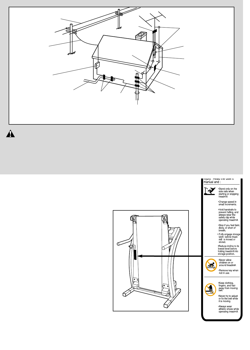
The decal shown at the right has been placed on your treadmill. If the decal is
missing or illegible, please call our Customer Service Department toll-free at
1-800-999-3756 to order a free replacement decal. Apply the decal in the location
shown.
Note: This decal is shown at the
right is 49% of actual size.
50%
Power Lines
Ground
Clamps Ground
Clamps
Ground
Clamp
Bonding
Jumper
Standoff
Insulators
Antenna
Lead-in Wire
Ground Wire
Ground
Wire Antenna
Discharge Unit
To External Antenna
Terminal of Treadmill
Mast
Service
Entrance
Equipment
Power Service Grounding
Electrode System (e.g.
Interior Metal Water Pipe)
Service
Entrance
Conductors
Optional Antenna Grounding Electrode Driven 8
Feet (2.44m) Into The Earth (If Required By Local
Codes). See NEC Section 810–21 (f).
6
Congratulations for purchasing the HealthRider®T90
treadmill. The T90 offers an impressive array of fea-
tures to help you achieve your fitness goals in the con-
venience of your home. And when you’re not exercis-
ing, the unique T90 can be folded up, requiring less
than half the floor space of other treadmills.
For your benefit, read this manual carefully before
using the treadmill. If you have questions after read-
ing the manual, please call our Customer Service
Department toll-free at 1-800-999-3756, Monday
through Friday, 6 a.m. until 6 p.m. Mountain Time (ex-
cluding holidays). To help us assist you, please note
the product model number and serial number before
calling. The model number is HRTL13910. The serial
number can be found on a decal attached to the tread-
mill (see the front cover of this manual for the location).
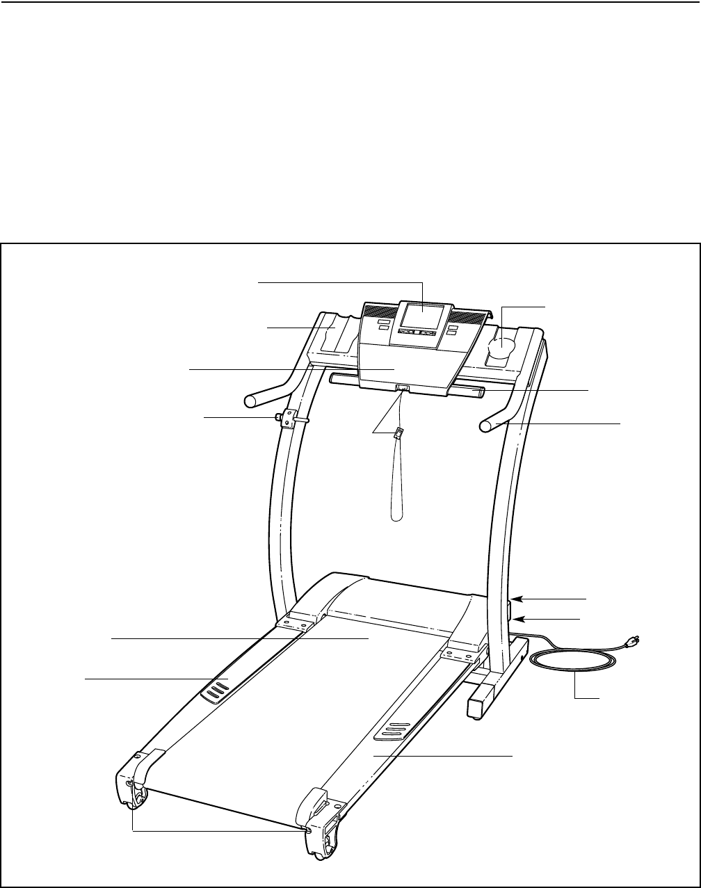
Before reading further, please familiarize yourself with
the parts that are labeled in the drawing below.
BEFORE YOU BEGIN
Handrail
Console
Hand Weight Holder*
Lock Knob
Personal Television
Key/Clip
Circuit Breaker
On/Off Switch
Walking Belt
Flexible Walking Platform
Foot Pad
Power Cord
Rear Roller
Adjustment Bolts
Water Bottle Holder†
Pulse Sensor
RIGHT SIDE
LEFT SIDE
*See page 21 for information
about optional hand weights.
†No water bottle is included.
ASSEMBLY
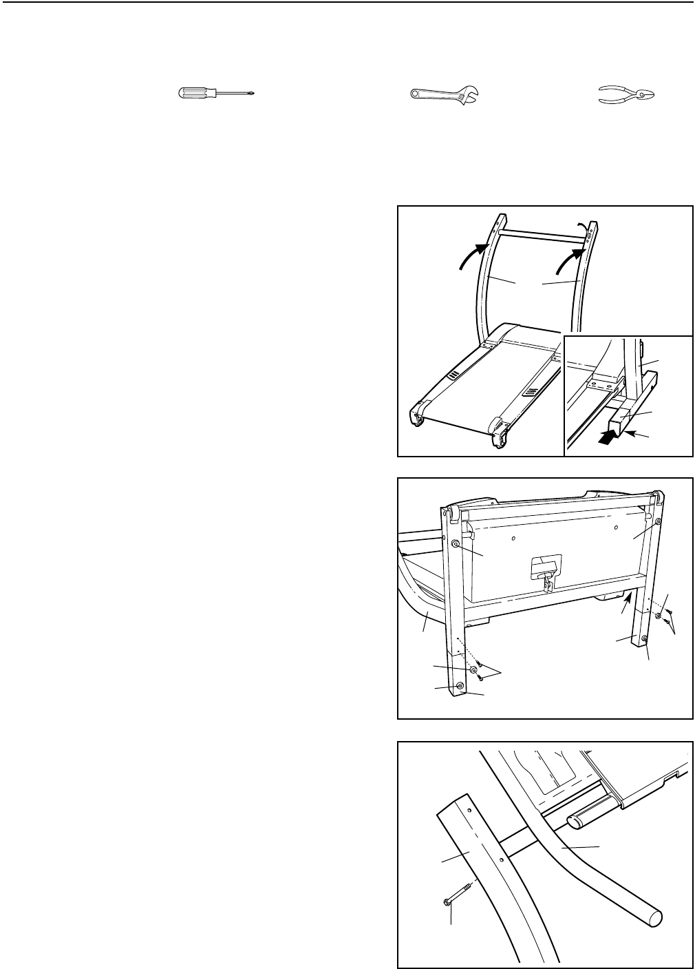
Assembly requires two people. Set the treadmill in a cleared area and remove all packing materials. Do not
dispose of the packing materials until assembly is completed. Assembly requires the included allen wrench
and a phillips screwdriver , an adjustable wrench , and wire cutters .
Note: The underside of the treadmill walking belt is coated with high-performance lubricant. During shipping, a
small amount of lubricant may be transferred to the top of the treadmill or the shipping carton. This is a normal
condition and does not affect treadmill performance. If there is lubricant on top of the walking belt or foot pads,
simply wipe off the lubricant with a soft cloth and a mild, non-abrasive cleaner.
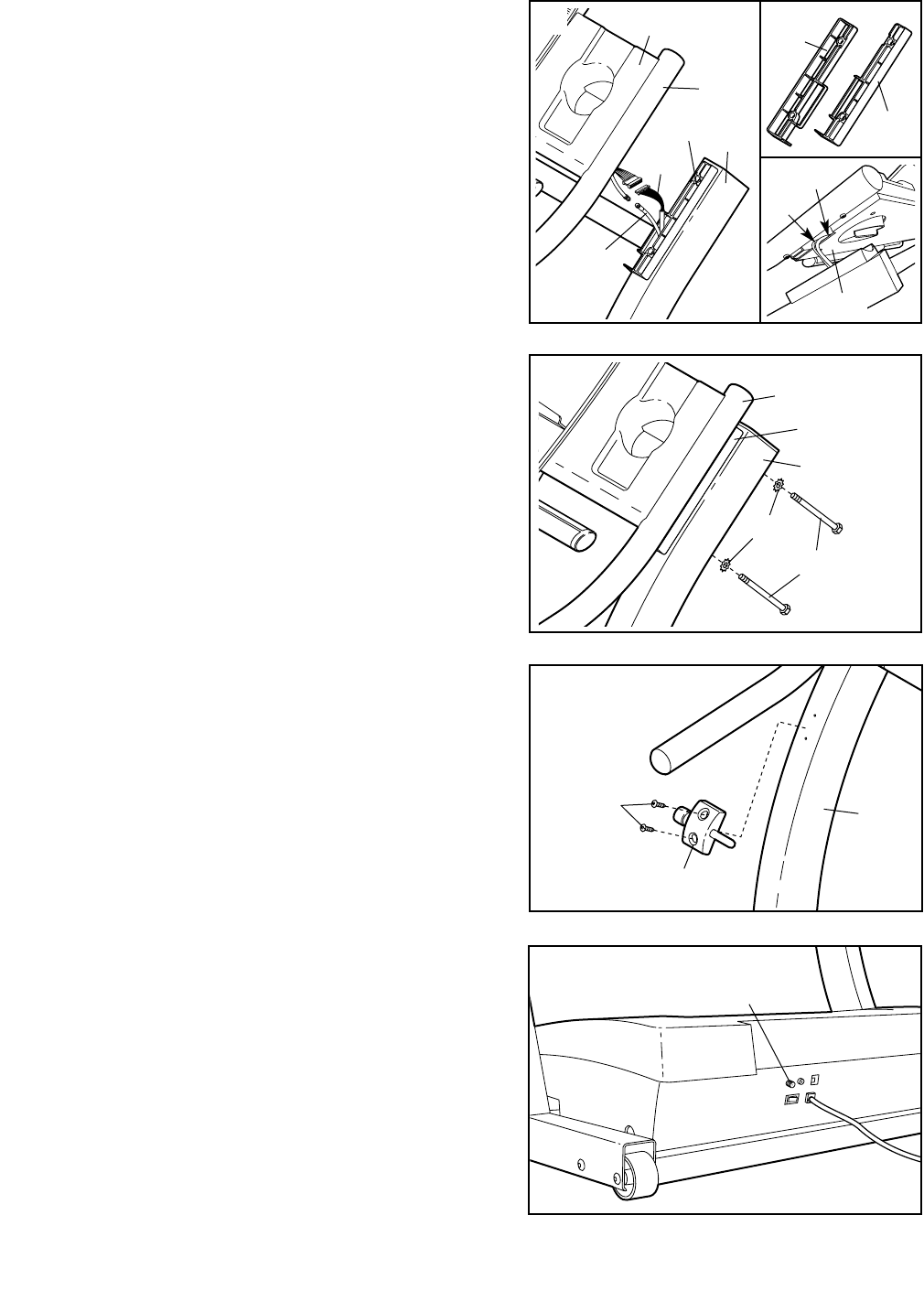
1. With the help of a second person, carefully raise the
Uprights (110) to the position shown.
Refer to the inset drawing. Insert one of the Extension
Legs (88) into the treadmill as shown. Make sure that
the Extension Leg is turned so the Thick Base Pad (90)
is on the bottom. Note: It may be helpful to tip the
Uprights (110) forward as you insert the Extension Leg.
Insert the other Extension Leg (not shown) in the same
way.
1
110
2. With the help of a second person, carefully tip the
Uprights (110) down as shown. Make sure that the
Extension Legs (88) remain in the Uprights.
Attach each Extension Leg (88) with two Base Screws
(86) and a Base Pad (75) as shown.
With the help of a second person, carefully tip the
Uprights (110) back to the vertical position.
Note: One replacement Thick Base Pad (90) may be in-
cluded. If a Thick Base Pad needs to be replaced, use
the replacement Thick Base Pad. 86
88
110
110
86
88
90
90
75
90 90
75
2
90
88
110
3. It may be helpful to set the Handrails (89) on the Uprights
(110) and loosely thread a Handrail Bolt (111) into the left
Upright and the left Handrail as shown. Tip the Handrails,
if necessary, to thread in the Bolt. Have another person
support the Handrails as you complete the remaining
steps.
110
89
111
3
8 . Make sure that all parts are tightened before you use the treadmill. Keep the included allen wrench in a
secure place. The allen wrench is used to adjust the walking belt (see page 27). To protect the floor or carpet
from damage, place a mat under the treadmill.
5. Insert two Handrail Bolts (111) with Handrail Washers
(112) into the right Upright (110) and the Right Handrail
Spacer (107). Lift the right Handrail (89) slightly and align
the Bolts with the holes in the Handrail. Loosely thread
the Bolts into the Handrail. Do not tighten the Bolts yet.
Refer to step 3. Remove the Handrail Bolt (111) from the
left Upright (110) and the left Handrail (89).
Place the Left Handrail Spacer (106, not shown) on the
left Upright (110, not shown). Attach the left Handrail (89)
as described above. Tighten all four Handrail Bolts (111).
111
112
110
89
4. Pull the Upright Wire Harness (101) and the TV Cable
(104) up through the Right Handrail Spacer (107) (refer to
drawing A to distinguish the Right Handrail Spacer from
the Left Handrail Spacer [106]). Place the Right Handrail
Spacer on the right Upright (110).
Connect the Upright Wire Harness (101) and the TV
Cable (104) to the two wires extending from the Console
Base (76). Insert the connectors, the Upright Wire
Harness, and the TV Cable into the hole in the Console
Base (refer to inset drawing B).
Set the Handrail (89) on the Right Handrail Spacer (107),
being careful not to pinch the Upright Wire Harness (101)
and the TV Cable (104).
4
101 110
89
76
107
104
107
106
76
101
104
A
B
107
6. Attach the Latch Assembly (109) to the left Upright (110)
with two Latch Screws (86).
109
110
86
6
7. Note the location of the 75 ohm antenna terminal on
the treadmill. For the television to operate properly, an
antenna, a CATV cable, or a VCR must be connected
to the 75 ohm antenna terminal.
If you are using an antenna, it must be properly con-
nected and adjusted for optimal reception. Refer to AN-
TENNA CONNECTIONS on page 22 to properly connect
an antenna. If you are using a CATV cable, refer to
CATV CABLE CONNECTION on page 22 to properly con-
nect the cable. If you are using a VCR, refer to HOW TO
CONNECT A VCR on page 24 to properly connect the
VCR. The VCR must be turned on, a videocassette
must be properly inserted, and the VCR must be play-
ing. Refer to your VCR user’s manual for operating in-
structions.
775 Ohm Antenna
Terminal
8
5
OPERATION AND ADJUSTMENT
THE PERFORMANT LUBETM WALKING BELT
Your treadmill features a walking belt coated with
PERFORMANT LUBETM, a high-performance lubricant.
IMPORTANT: Never apply silicone spray or other
substances to the walking belt or the walking plat-
form. Such substances will deteriorate the walking
belt and cause excessive wear.
HOW TO PLUG IN THE POWER CORD
Your treadmill, like any other type of sophisticated
electronic equipment, can be seriously damaged by
sudden voltage changes in your home’s power.
Voltage surges, spikes, and noise interference can
result from weather conditions or from other appliances
being turned on or off. To decrease the possibility of
your treadmill being damaged, always use a surge
suppressor with your treadmill (see drawing 1 at
the right). To purchase a surge suppressor, see
your local HealthRider dealer or call 1-800-806-3651
and order part number 146148.
Use only a single-outlet surge suppressor that is
UL 1449 listed as a transient voltage surge sup-
pressor (TVSS). The surge suppressor must have a
UL suppressed voltage rating of 400 volts or less
and a minimum surge dissipation of 450 joules.
The surge suppressor must be electrically rated
for 120 volts AC and 15 amps. There must be a
monitoring light on the surge suppressor to indi-
cate whether it is functioning properly. Failure to
use a properly functioning surge suppressor could
result in damage to the control system of the
treadmill. If the control system is damaged, the
walking belt may change speed or stop unexpect-
edly, which may result in a fall and serious injury.
This product must be grounded. If it should malfunc-
tion or break down, grounding provides a path of least
resistance for electric current to reduce the risk of elec-
tric shock. This product is equipped with a cord having
an equipment-grounding conductor and a grounding
plug. Plug the power cord into a surge suppressor,
and plug the surge suppressor into an appropriate
outlet that is properly installed and grounded in
accordance with all local codes and ordinances.
Important: The treadmill is not compatible with
GFCI-equipped outlets.
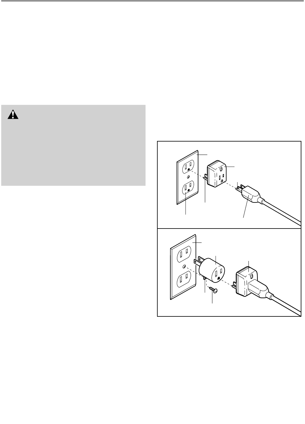
This product is for use on a nominal 120-volt circuit,
and has a grounding plug that looks like the plug illus-
trated in drawing 1 below. A temporary adapter that
looks like the adapter illustrated in drawing 2 may be
used to connect the surge suppressor to a 2-pole
receptacle as shown in drawing 2 if a properly
grounded outlet is not available.
The temporary adapter should be used only until a
properly grounded outlet (drawing 1) can be installed
by a qualified electrician.
The green-colored rigid ear, lug, or the like extending
from the adapter must be connected to a permanent
ground such as a properly grounded outlet box cover.
Whenever the adapter is used it must be held in place
by a metal screw. Some 2-pole receptacle outlet box
covers are not grounded. Contact a qualified elec-
trician to determine if the outlet box cover is
grounded before using an adapter.
DANGER: Improper connection
of the equipment-grounding conductor can
result in an increased risk of electric shock.
Check with a qualified electrician or service-
man if you are in doubt as to whether the
product is properly grounded. Do not modify
the plug provided with the product—if it will
not fit the outlet, have a proper outlet
installed by a qualified electrician.
1
2
Grounded Outlet Box
Grounded Outlet Box
Grounding Plug
Surge Suppressor
Surge Suppressor
Grounding Pin
Adapter
Lug
Metal Screw
Grounded Outlet
Grounding Pin
10
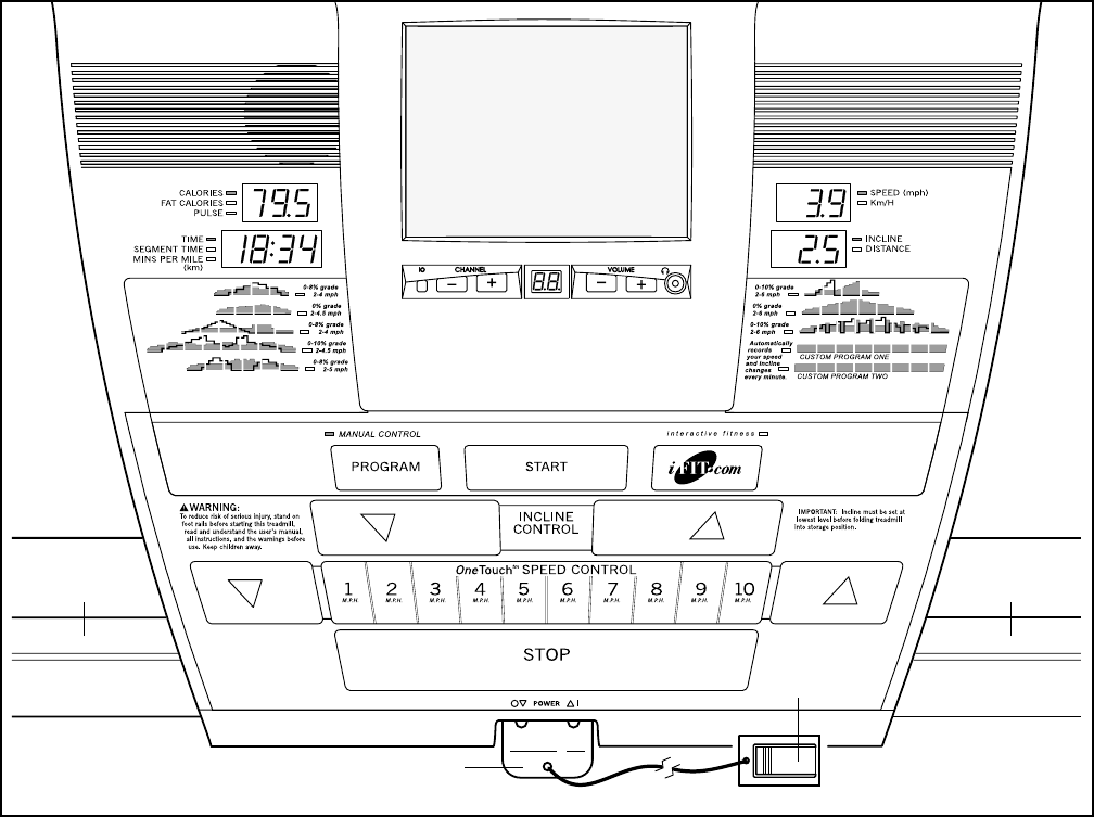
FEATURES OF THE CONSOLE
The advanced console offers an impressive array of
features to help you get the most from your exercise.
When the console is in the manual mode, the speed
and incline of the treadmill can be changed with a touch
of a button. As you exercise, the console will provide
continuous exercise feedback. You can even measure
your heart rate using the built-in pulse sensor.
Eight preset workout programs are also offered. Each
program automatically controls the speed and incline
of the treadmill to give you an effective workout. You
can even create your own custom workout programs
and store them in memory for future use.
Whether you select the manual mode or use a workout
program, the personal television will allow you to watch
the program of your choice while you get in shape.
The console also features new iFIT.com interactive
technology. IFIT.com technology is like having a per-
sonal trainer right in your home. Using the included
audio cable, you can connect the treadmill to your
home stereo, portable stereo, or computer and play
special iFIT.com CD programs (iFIT.com CDs are avail-
able separately). IFIT.com CD programs automatically
control the speed and incline of the treadmill as a per-
sonal trainer guides you through every step of your
workout. High-energy music provides added motivation.
Each CD features two programs designed by certified
personal trainers.
In addition, you can connect the treadmill to your VCR
and TV and play iFIT.com video programs (videocas-
settes are available separately). Video programs offer
the same benefits as iFIT.com CD programs, but add
the excitement of working out with a class and an
instructor—the hottest new trend at health clubs.
With the treadmill connected to your computer, you
can also go to our Web site at www.iFIT.com and ac-
cess basic programs, audio programs, and video pro-
grams directly from the internet. Additional options are
soon to be available. See www.iFIT.com for details.
To purchase iFIT.com CDs or videocassettes, call toll-
free 1-800-735-0768. For information about an optional
chest pulse sensor or other accessories, see page 21.
Note: If there are thin sheets of
clear plastic on the face of the
console, remove them.
Pulse
Sensor Pulse
Sensor
Clip
Key
GETTING STARTED
Attach the clip to the waistband of your clothes.
Stand on the foot pads
of the treadmill. Find
the clip attached to the
key and slide the clip
onto the waistband of
your clothes. Next, in-
sert the key into the
console. Test the clip
by carefully taking a few steps backward until
the key is pulled from the console. If the key is
not pulled from the console, adjust the posi-
tion of the clip as needed. Then, remove the key
from the console.
Plug in the power cord.
See HOW TO PLUG IN THE POWER CORD on
page 9.
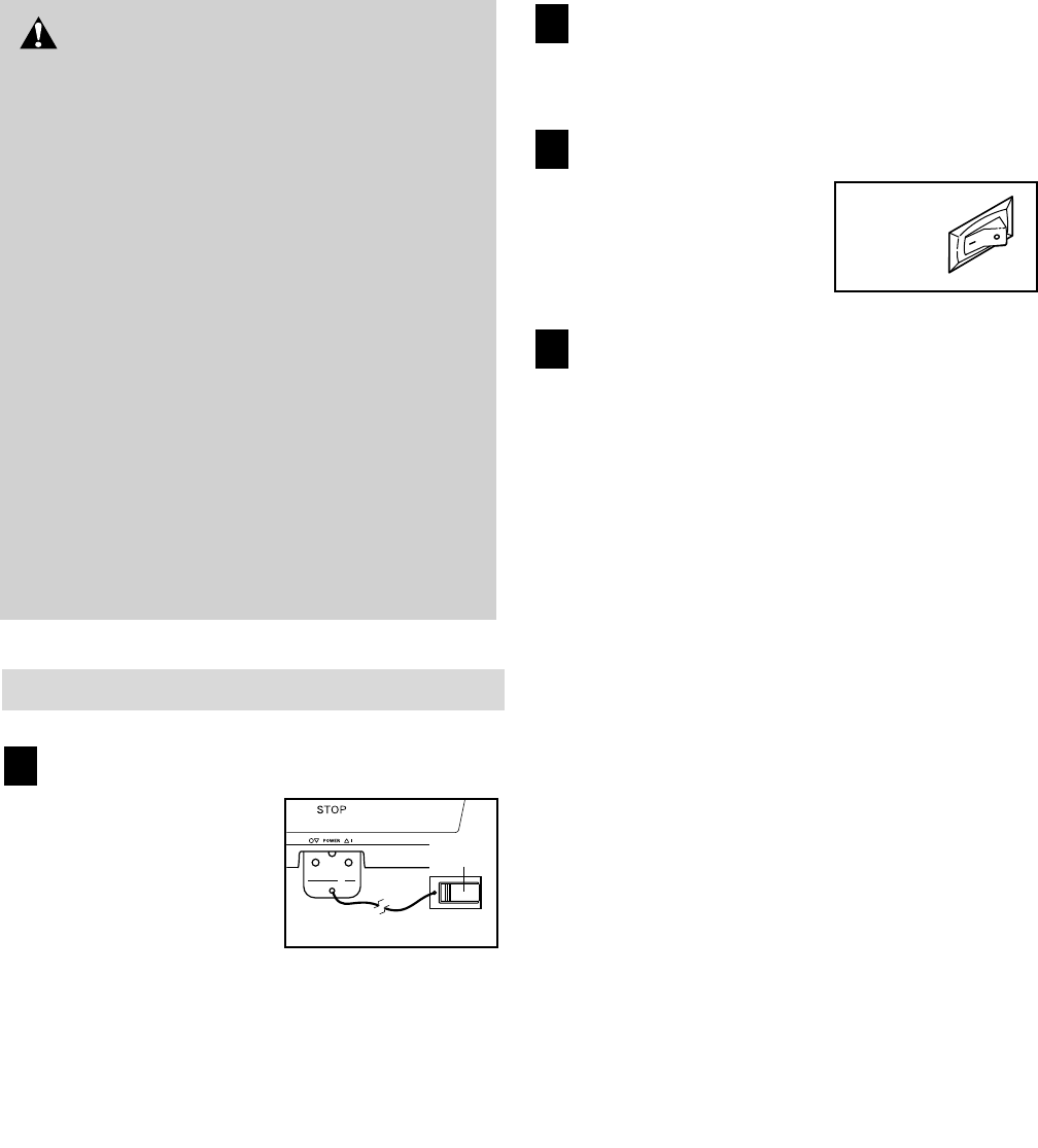
Move the on/off switch to the on position.
Locate the on/off switch
on the treadmill near the
power cord. Move the
on/off switch to the on
position.
Insert the key fully into the console.
Stand on the foot pads of the treadmill. Make sure
that the clip is securely attached to the waistband
of your clothes. Next, insert the key into the con-
sole. After a moment, the displays and various in-
dicators on the console will light.
To use the manual mode of the console, follow the
steps beginning on page 12. To use a preset program,
see page 13. To create and use a custom program,
see pages 14 and 15. To use an iFIT.com CD or
video program, see page 18. To use an iFIT.com
program directly from our Web site, see page 20.
To operate the personal television, follow the in-
structions beginning on page 22. IMPORTANT: For
the television to operate properly, an antenna, a
CATV cable, or a VCR must be connected to the 75
ohm antenna terminal on the treadmill.
If you are using an antenna, it must be properly con-
nected and adjusted. See ANTENNA CONNECTIONS
on page 22 to properly connect an antenna. If you are
using a CATV cable, see CATV CABLE CONNEC-
TION on page 22 to connect the cable. If you are
using a VCR, see HOW TO CONNECT A VCR on
page 24 to properly connect the VCR.
Note: During the first few minutes that you use the
treadmill, inspect the alignment of the walking belt, and
align the walking belt if necessary (see page 27).
4
3
2
1
CAUTION:Before operating the
console, read the following precautions.
• Do not stand on the walking belt when turn-
ing on the power.
• Always wear the clip (see the drawing below)
while operating the treadmill.
•Adjust the speed in small increments to
avoid sudden jumps in speed.
•The pulse sensor is not a medical device.
Various factors, including the user’s move-
ment, may affect the accuracy of heart rate
readings. The pulse sensor is intended only
as an exercise aid in determining heart rate
trends in general.
•To reduce the possibility of electric shock,
keep the console dry. Avoid spilling liquids
on the console and place only a sealed water
bottle in the water bottle holder.
On
Position
Clip
12
HOW TO USE THE MANUAL MODE
Insert the key fully into the console.
See GETTING STARTED on page 11.
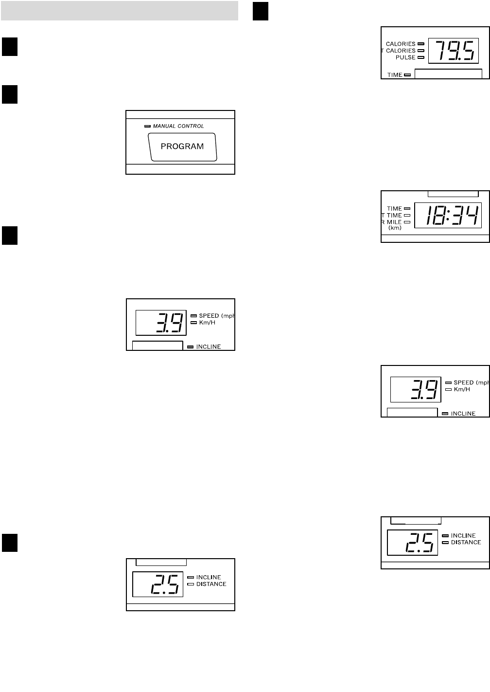
Select the manual mode.
When the key is in-
serted, the manual
mode will be se-
lected and the
Manual Control indi-
cator will light. If the
iFIT.com mode or a
program has been selected, press the Program
button repeatedly to select the manual mode.
Press the Start button or the Speed
▲▲
button to
start the walking belt.
A moment after the button is pressed, the walking
belt will begin to move at 1 mph. Hold the handrails
and begin walking.
As you exercise,
change the speed of
the walking belt as
desired by pressing
the Speed
▲▲
and
▼▼
buttons. Each time a
button is pressed, the speed setting will change
by 0.1 mph; if a button is held down, the speed
setting will change in increments of 0.5 mph. To
change the speed setting quickly, press the
OneTouch Speed buttons. The speed range is 0.5
mph to 10 mph. Note: After the buttons are
pressed, it may take a moment for the treadmill to
reach the selected speed setting.
To stop the walking belt, press the Stop button.
The Time/Pace display will begin to flash. To
restart the walking belt, press the Start button or
the Speed
▲▲
button.
Change the incline of the treadmill as desired.
To change the in-
cline of the treadmill,
press the Incline
▲▲
and
▼▼
buttons. Each
time a button is
pressed, the incline
will change by 0.5%. The incline range is 0% to
10%. Note: After the buttons are pressed, it may
take a moment for the treadmill to reach the se-
lected incline setting.
Follow your progress with the four displays.
Calories/Pulse dis-
play—This display
shows the approxi-
mate numbers of
calories and fat calo-
ries you have burned
(see FAT BURNING on page 29 for an explana-
tion of fat calories). The display will change from
one number to the other every few seconds, as
shown by the indicators beside the display. When
you use the handgrip pulse sensor (see step 6 on
page 12) or the optional chest pulse sensor (see
page 21), the display will also show your heart rate.
Time/Pace
display—When the
manual mode or the
iFIT.com mode is se-
lected, this display
will show the elapsed
time and your current pace (pace is measured in
minutes per mile). When a program is selected,
the display will show the time remaining in the pro-
gram, the time remaining in the current segment of
the program, and your current pace. The display
will change from one number to the next every few
seconds, as shown by the indicators beside the
display.
Speed display—This
display shows the
speed of the walking
belt. Note: If the
Speed indicator be-
side the display is lit,
the speed and distance will be displayed in miles.
If the Km/H indicator is lit, speed and distance will
be displayed in kilometers. To change the unit of
measurement, refer to THE INFORMATION MODE/
DEMO MODE on page 21. Note: For simplicity,
all instructions in this manual refer to miles.
Incline/Distance
display—This dis-
play shows the in-
cline level of the
treadmill and the dis-
tance that you have
walked or run. The display will change from one
number to the other every few seconds, as shown
by the indicators beside the display.
To reset the displays, press the Stop button, re-
move the key, and then reinsert the key.
5
4
3
2
1

Measure your heart rate, if desired.
To measure your
heart rate, stand
on the foot pads
and place your
hands on the
metal contacts on
the handrail. Your
palms must be
resting on the con-
tacts closest to
you, and your fin-
gers must be touching the other contacts—avoid
moving your hands. When your pulse is detected,
the Pulse indicator will light, two or three dashes
(– – –) will appear in the Calories/Pulse display,
and then your heart rate will be shown. For the
most accurate heart rate reading, continue to
hold the contacts for about 15 seconds.
When you are finished exercising, stop the
walking belt and remove the key.
Step onto the foot rails, press the Stop button, and
adjust the incline of the treadmill to the lowest level.
The incline must be at the lowest level when
the treadmill is raised to the storage position or
the treadmill will be damaged. Next, remove the
key from the console and put it in a secure place.
Note: If the displays and indicators on the con-
sole remain lit after the key is removed, the
console is in the “demo” mode. See page 21
and turn off the demo mode.
When you are finished using the treadmill, move
the on/off switch near the power cord to the off
position and unplug the power cord.
HOW TO USE A PRESET PROGRAM
Insert the key fully into the console.
See GETTING STARTED on page 11.
Select one of the eight preset programs.
When the key is
inserted, the
manual mode will
be selected. To
select one of the
preset programs,
press the
Program button
repeatedly until one of the eight program indicators
lights. When a preset program is selected, the
Time/Pace display will show how long the program
will last. In addition, the Speed display and the
Incline/Distance display will flash the maximum
speed setting and the maximum incline setting for
the program for six seconds.
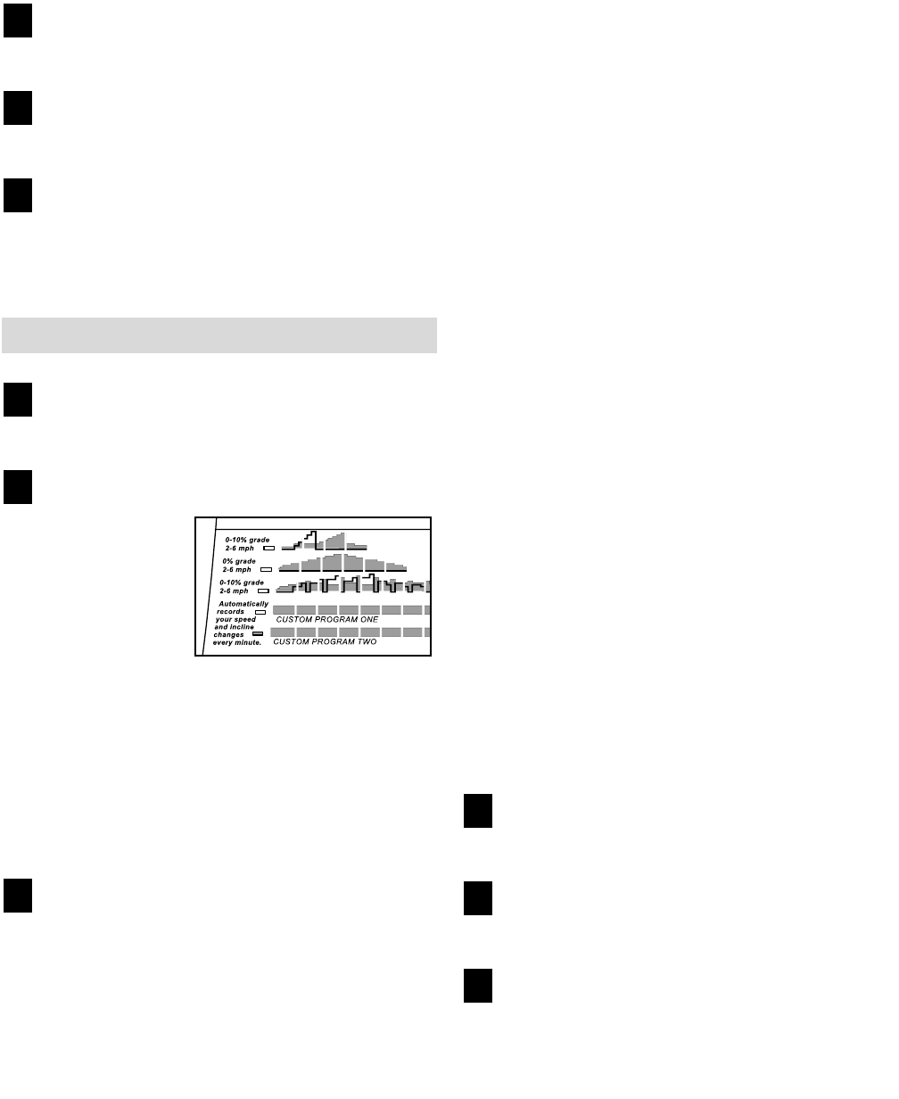
The profiles below the displays show how the
speed and incline of the treadmill will change dur-
ing the preset programs. The numbers beside the
profiles show the speed and incline ranges for the
programs. For example, the upper left profile
shows that the speed and incline of the treadmill
will gradually increase during the first half of that
program, and then decrease during the last half.
The speed range for the program is 2 to 4 mph,
and the incline range is 0 to 8%.
Press the Start button or the Speed
▲▲
button to
start the program.
A moment after the button is pressed, the tread-
mill will automatically adjust to the first speed and
incline settings for the program. Hold the handrails
and begin walking.
Each program is divided into several time seg-
ments of different lengths. One speed setting and
one incline setting are programmed for each seg-
ment. (The same speed setting and/or incline set-
ting may be programmed for one or more consecu-
tive segments.) When only three seconds remain in
the first segment of the program, a series of tones
will sound and the Speed display and/or the
Incline/Distance display will flash to alert you that
the speed and/or the incline of the treadmill is
about to change. When the segment is completed,
the treadmill will automatically adjust to the speed
and incline settings for the second segment.
3
2
1
7
6

14
The program will continue in this way until the
Time/Pace display shows that no time remains in
the program. The walking belt will then slow to a
stop.
If the speed or incline setting for the current
segment is too high or too low, you can manually
override the setting by pressing the Speed or
Incline buttons on the console. Note: If you man-
ually override the speed or incline setting for
the current segment, when the segment ends
the treadmill will automatically adjust to the
speed and incline settings for the next seg-
ment.
To stop the program temporarily, press the Stop
button. The Time/Pace display will begin to flash.
To restart the program, press the Start button or
the Speed
▲▲
button. To end the program, press
the Stop button, remove the key, and then reinsert
the key.
Follow your progress with the four displays.
See step 5 on page 12.
Measure your heart rate, if desired.
See step 6 on page 13.
When the program has ended, remove the key.
Step onto the foot rails and make sure that the in-
cline of the treadmill is at the lowest level. The in-
cline must be at the lowest level when the
treadmill is raised to the storage position. Next,
remove the key from the console and put it in a se-
cure place. Note: If the displays and indicators
on the console remain lit after the key is re-
moved, the console is in the “demo” mode.
See page 21 and turn off the demo mode.
When you are finished using the treadmill, move
the on/off switch near the power cord to the off
position and unplug the power cord.
HOW TO CREATE A CUSTOM PROGRAM
Insert the key fully into the console.
See GETTING STARTED on page 11.
Select one of the custom programs.
When the key is
inserted, the
manual mode will
be selected. To
select one of the
custom pro-
grams, press the
Program button
repeatedly until the Custom Program One or
Custom Program Two indicator lights.
Press the Start button or the Speed
▲▲
button
and program the desired speed and incline
settings.
A moment after the button is pressed, the walking
belt will begin to move. Hold the handrails and
begin walking.
Each custom program is divided into one-minute
segments. One speed setting and one incline set-
ting can be programmed for each segment. To
program a speed setting and an incline setting for
the first segment, simply adjust the speed and in-
cline of the treadmill to the desired levels with the
Speed and Incline buttons. During the last three
segments of the first segment, a series of tones
will sound and the Speed display and the
Incline/Distance display will flash. When the first
segment is completed, the current speed setting
and the current incline setting will be saved in
memory. Program a speed setting and an incline
setting for the second segment as described
above.
Continue programming speed and incline settings
for as many segments as desired; custom pro-
grams can have up to forty segments. When you
are finished with your workout, press the Stop but-
ton twice. The speed and incline settings that you
programmed and the number of segments that you
programmed will then be saved in memory.
3
2
1
6
5
4
Follow your progress with the four displays.
See step 5 on page 12.
Measure your heart rate, if desired.
See step 6 on page 13.
When the program has ended, remove the key.
See step 6 on page 14.
HOW TO USE A CUSTOM PROGRAM
Insert the key fully into the console.
See GETTING STARTED on page 11.
Select one of the custom programs.
When the key is
inserted, the
manual mode
will be selected.
To select one of
the custom pro-
grams, press the
Program button
repeatedly until the Custom Program One or
Custom Program Two indicator lights. When a cus-
tom program is selected, the Time/Pace display will
show how long the program will last. In addition,
the Speed display and the Incline/Distance display
will flash the maximum speed setting and the
maximum incline setting for the program for six
seconds.
Press the Start button or the Speed
▲▲
button to
start the program.
A moment after the button is pressed, the tread-
mill will automatically adjust to the first speed and
incline settings for the program. Hold the handrails
and begin walking.
Each program is divided into several one-minute
segments. One speed setting and one incline set-
ting are programmed for each segment. When
only three seconds remain in the first segment of
the program, a series of tones will sound and the
Speed display and the Incline/Distance display will
flash to alert you that the speed and/or the incline
of the treadmill is about to change. When the seg-
ment is completed, the treadmill will automatically
adjust to the speed and incline settings for the
second segment.
The program will continue in this way until the
Time/Pace display shows that no time remains in
the program. The walking belt will then slow to a
stop.
If desired, you can redefine to the program while
using the program. To change the speed or in-
cline setting during the current segment, sim-
ply press the Speed or Incline buttons. When the
current segment is completed, the new setting will be
saved in memory. To increase the length of the
program, first wait until the program is completed.
Then, press the Start button and program speed and
incline settings for as many additional segments as
desired. When you have added as many segments
as desired, press the Stop button twice. To de-
crease the length of the program, press the Stop
button twice at any time before the program is com-
pleted.
To stop the program temporarily, press the Stop
button. All displays will pause and the Time/Pace
display will begin to flash. To restart the program,
press the Start button or the Speed
▲▲
button. To
end the program, press the Stop button, remove
the key, and then reinsert the key.
Follow your progress with the four displays.
See step 5 on page 12.
Measure your heart rate, if desired.
See step 6 on page 13.
When the program has ended, remove the key.
See step 6 on page 14.
6
5
4
3
2
1
6
5
4
16
HOW TO CONNECT THE TREADMILL TO YOUR
CD PLAYER, VCR, OR COMPUTER
To use iFIT.com CDs, the treadmill must be con-
nected to your portable CD player, portable stereo,
home stereo, or computer with CD player. See pages
16 and 17 for connecting instructions. To use iFIT.com
videocassettes, the treadmill must be connected to
your VCR. See page 18 for connecting instructions. To
use iFIT.com programs directly from our Web site,
the treadmill must be connected to your home com-
puter. See page 17 for connecting instructions.
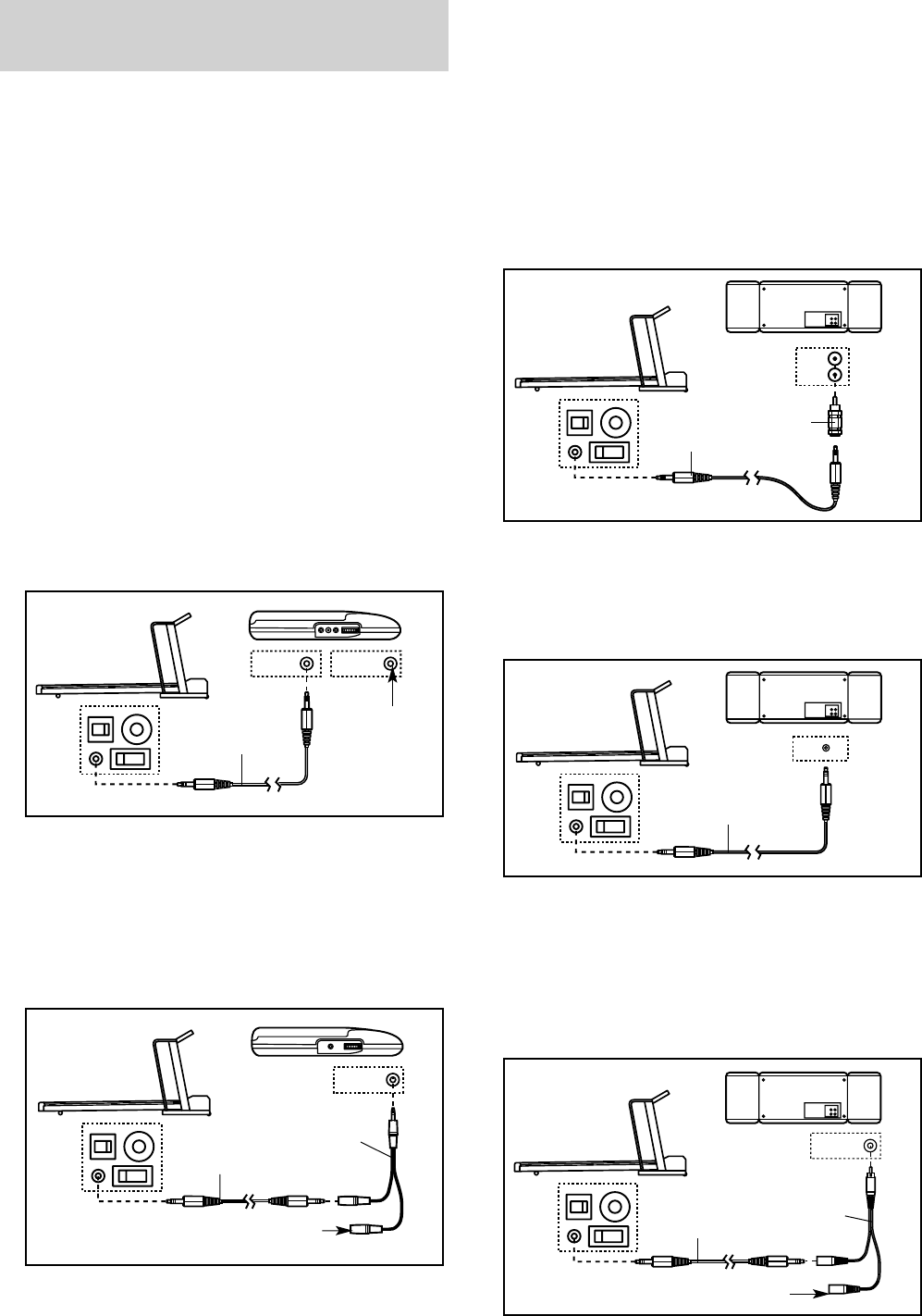
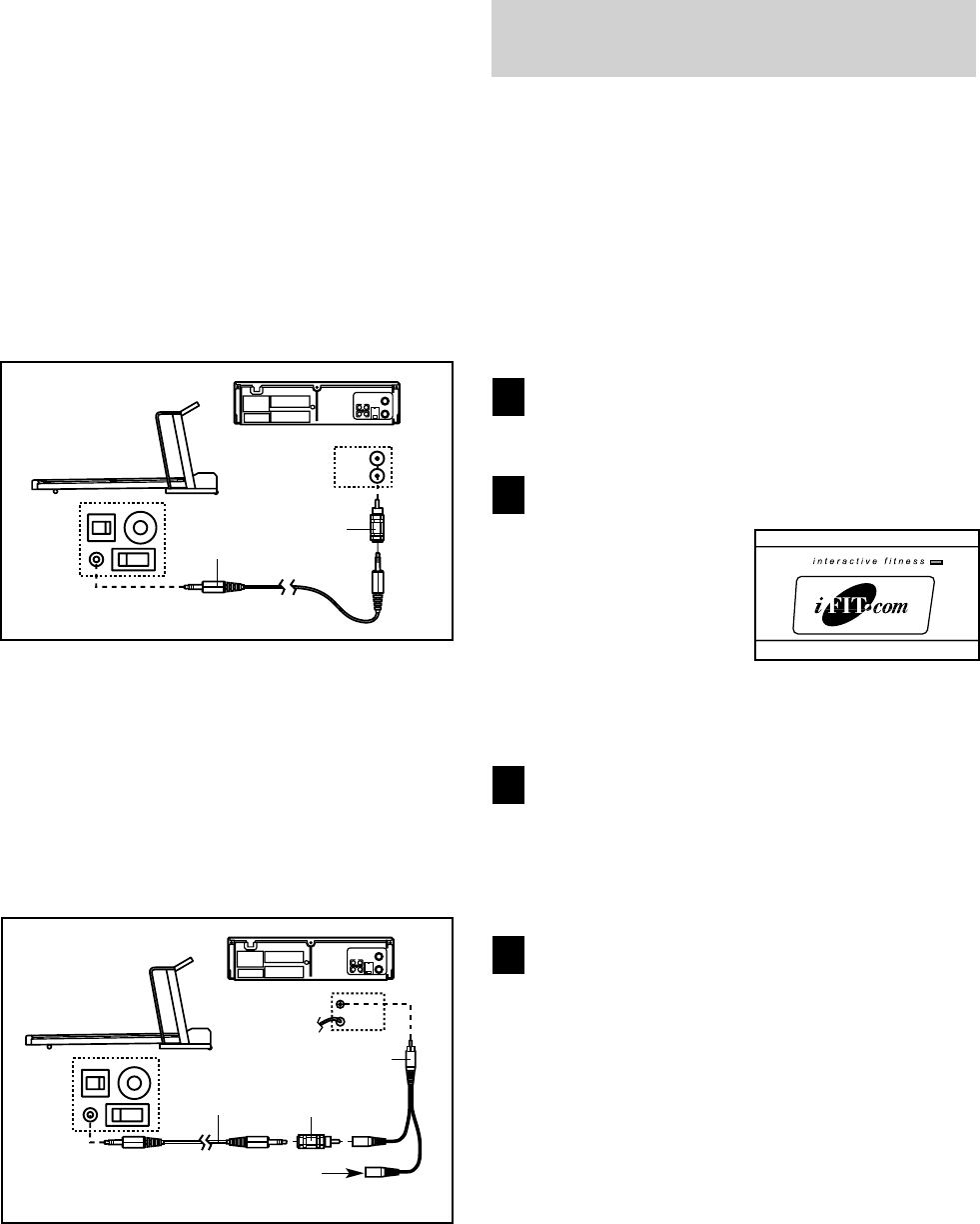
HOW TO CONNECT YOUR PORTABLE CD PLAYER
Note: If your CD player has separate LINE OUT and
PHONES jacks, see instruction A below. If your CD
player has only one jack, see instruction B.
A. Plug one end of the audio cable into the jack on the
front of the treadmill near the power cord. Plug the
other end of the cable into the LINE OUT jack on
your CD player. Plug your headphones into the
PHONES jack.
B. Plug one end of the audio cable into the jack on the
front of the treadmill near the power cord. Plug the
other end of the cable into a 3.5mm Y-adapter
(available at electronics stores). Plug the Y-adapter
into the PHONES jack on your CD player. Plug your
headphones into the other side of the Y-adapter.
HOW TO CONNECT YOUR PORTABLE STEREO
Note: If your stereo has an RCA-type AUDIO OUT
jack, see instruction A below. If your stereo has a
3.5mm LINE OUT jack, see instruction B. If your
stereo has only a PHONES jack, see instruction C.
A. Plug one end of the audio cable into the jack on the
front of the treadmill near the power cord. Plug the
other end of the cable into the included adapter. Plug
the adapter into an AUDIO OUT jack on your stereo.
B. Plug one end of the audio cable into the jack on the
front of the treadmill near the power cord. Plug the
other end of the cable into the LINE OUT jack on
your stereo.
C. Plug one end of the audio cable into the jack on the
front of the treadmill near the power cord. Plug the
other end of the cable into a 3.5mm Y-adapter
(available at electronics stores). Plug the Y-adapter
into the PHONES jack on your stereo. Plug your
headphones into the other side of the Y-adapter.
LINE OUT
PHONES LINE OUT
PHONES
Audio
Cable
Head-
phones
A
AUDIO OUT
RIGHT
LEFT
Audio
Cable Adapter
A
LINE OUT
Audio
Cable
B
PHONES
Audio
Cable
C
PHONES
PHONES
Audio
Cable
3.5mm
Y-adapter
Headphones
B
3.5mm
Y-adapter
Headphones
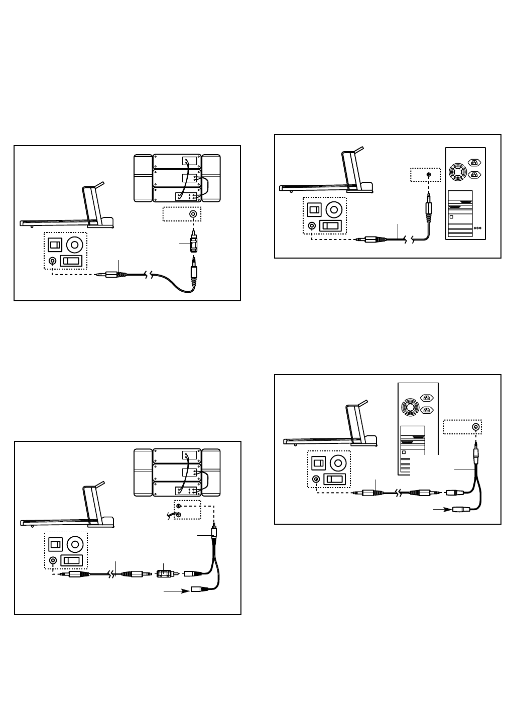
HOW TO CONNECT YOUR HOME STEREO
Note: If your stereo has an unused LINE OUT jack,
see instruction A below. If the LINE OUT jack is
being used, see instruction B.
A. Plug one end of the audio cable into the jack on the
front of the treadmill near the power cord. Plug the
other end of the cable into the included adapter.
Plug the adapter into the LINE OUT jack on your
stereo.
B. Plug one end of the audio cable into the jack on the
front of the treadmill near the power cord. Plug the
other end of the cable into the included adapter.
Plug the adapter into an RCA Y-adapter (available
at electronics stores). Next, remove the wire that is
currently plugged into the LINE OUT jack on your
stereo and plug the wire into the unused side of the
RCA Y-adapter. Plug the RCA Y-adapter into the
LINE OUT jack on your stereo.
HOW TO CONNECT YOUR COMPUTER
Note: If your computer has a 3.5mm LINE OUT jack,
see instruction A. If your computer has only a
PHONES jack, see instruction B.
A. Plug one end of the audio cable into the jack on the
front of the treadmill near the power cord. Plug the
other end of the cable into the LINE OUT jack on
your computer.
B. Plug one end of the audio cable into the jack on the
front of the treadmill near the power cord. Plug the
other end of the cable into a 3.5mm Y-adapter
(available at electronics stores). Plug the Y-adapter
into the PHONES jack on your computer. Plug your
headphones or speakers into the other side of the
Y-adapter.
LINE OUT
CD
VCR
Amp
LINE OUT
Audio
Cable Adapter
A
LINE OUT
Audio
Cable
A
CD
VCR
Amp
LINE OUT
Audio
Cable
RCA
Y-adapter
Wire removed from
LINE OUT jack
B
Adapter
PHONES
Audio
Cable
B
3.5mm
Y-adapter
Headphones/Speakers
18
HOW TO CONNECT YOUR VCR
Note: If your VCR has an unused AUDIO OUT jack,
see instruction A below. If the AUDIO OUT jack is
being used, see instruction B. If you have a TV
with a built-in VCR, see instruction B. If your VCR
is connected to your home stereo, see HOW TO
CONNECT YOUR HOME STEREO on page 17.
A. Plug one end of the audio cable into the jack on the
front of the treadmill near the power cord. Plug the
other end of the cable into the included adapter.
Plug the adapter into the AUDIO OUT jack on your
VCR.
B. Plug one end of the audio cable into the jack on the
front of the treadmill near the power cord. Plug the
other end of the cable into the included adapter.
Plug the adapter into an RCA Y-adapter (available
at electronics stores). Next, remove the wire that is
currently plugged into the AUDIO OUT jack on your
VCR and plug the wire into the unused side of the
RCA Y-adapter. Plug the RCA Y-adapter into the
AUDIO OUT jack on your VCR.
HOW TO USE IFIT.COM CD AND VIDEO
PROGRAMS
To use iFIT.com CDs or videocassettes, the treadmill
must be connected to your portable CD player, portable
stereo, home stereo, computer with CD player, or
VCR. See HOW TO CONNECT THE TREADMILL TO
YOUR CD PLAYER, VCR, OR COMPUTER on pages
16 to 18. Note: To purchase iFIT.com CDs or video-
cassettes, call toll-free 1-800-735-0768.
Follow the steps below to use an iFIT.com CD or video
program.
Insert the key fully into the console.
See GETTING STARTED on page 11.
Select the iFIT.com mode.
When the key is in-
serted, the manual
mode will be selected.
To use an iFIT.com
CD or video program,
press the iFIT.com
button or press the
Program button repeatedly until the Interactive
Fitness indicator lights.
Insert the iFIT.com CD or videocassette.
If you are using an iFIT.com CD, insert the CD
into your CD player. If you are using an iFIT.com
videocassette, insert the videocassette into your
VCR.
Press the PLAY button on your CD player or
VCR.
A moment after the button is pressed, your per-
sonal trainer will begin guiding you through your
workout. Simply follow your personal trainer’s
instructions. Note: If the Time/Pace display is
flashing, press the Start button or the Speed
▲▲
button on the console. The treadmill will not re-
spond to a CD or video program when the
Time/Pace display is flashing.
During the CD or video program, an electronic
“chirping” sound will alert you when the speed
and/or the incline of the treadmill is about to
change. CAUTION: Always listen for the “chirp”
and be prepared for speed and/or incline
changes. In some instances, the speed and/or
the incline may change before the personal
trainer describes the change.
4
3
2
1
AUDIO OUT
RIGHT
LEFT
VIDEO AUDIO
ANT. IN
RF OUT
IN
OUT
CH
34
Audio
Cable Adapter
A
VIDEO AUDIO
ANT. IN
RF OUT
IN
OUT
CH
34
Audio
Cable Adapter
B
Wire removed from
AUDIO OUT jack
RCA Y-adapter

If the speed or incline settings are too high or too
low, you can manually override the settings at any
time with the Speed or Incline buttons on the con-
sole. However, when the next “chirp” is heard,
the speed and/or the incline will change to the
next settings for the CD or video program.
To stop the walking belt at any time, press the
Stop button on the console. The Time/Pace dis-
play will begin to flash. To restart the program,
press the Start button or the Speed
▲▲
button.
After a moment, the walking belt will begin to
move at 1 mph. When the next “chirp” is heard,
the speed and incline will change to the next
settings for the CD or video program.
When the CD or video program is completed, the
walking belt will stop and the Time/Pace display
will begin to flash. Note: To use another CD or
video program, press the Stop button or remove
the key and go to step 1 on page 18.
Note: If the speed or incline of the treadmill
does not change when a “chirp” is heard:
• Make sure that the iFIT.com indicator is lit and
that the Time/Pace display is not flashing. If
the Time/Pace display is flashing, press the
Start button or the Speed + button on the
console.
• Adjust the volume of your CD player or VCR.
If the volume is too high or too low, the con-
sole may not detect the program signals.
• Make sure that the audio cable is properly
connected, that it is fully plugged in, and that
it is not wrapped around a power cord.
• If you are using your portable CD player and
the CD skips, set the CD player on the floor or
another flat surface instead of on the console.
• See the bottom of page 27.
Follow your progress with the four displays.
See step 5 on page 12.
Measure your heart rate, if desired.
See step 6 on page 13.
When the program is completed, remove the
key.
See step 6 on page 14.
CAUTION: Always remove iFIT.com CDs and
videocassettes from your CD player or VCR
when you are finished using them.
7
6
5

20
HOW TO USE PROGRAMS DIRECTLY FROM
OUR WEB SITE
Our Web site at www.iFIT.com allows you to access
basic programs, audio programs, and video programs
directly from the internet. Additional options are soon
to be available. See www.iFIT.com for details.
To use programs from our Web site, the treadmill must
be connected to your home computer. See HOW TO
CONNECT YOUR COMPUTER on page 17. In
addition, you must have an internet connection and
an internet service provider. A list of specific system
requirements will be found on our Web site.
Follow the steps below to use a program from our
Web site.
Insert the key fully into the console.
See GETTING STARTED on page 11.
Select the iFIT.com mode.
When the key is in-
serted, the manual
mode will be se-
lected. To use a pro-
gram from our Web
site, press the
iFIT.com button or
press the Program button repeatedly until the
Interactive Fitness indicator lights.
Go to your computer and start an internet
connection.
Start your web browser, if necessary, and go to
our Web site at www.iFIT.com.
Follow the desired links on our Web site to se-
lect a program.
Read and follow the on-line instructions for using a
program.
Follow the on-line instructions to start the
program.
When you start the program, an on-screen count-
down will begin.
Return to the treadmill and stand on the foot
pads. Find the clip attached to the key and slide
the clip onto the waistband of your clothes.
When the on-screen countdown ends, the program
will begin and the walking belt will begin to move.
Hold the handrails, step onto the walking belt, and
begin walking. During the program, an electronic
“chirping” sound will alert you when the speed
and/or the incline of the treadmill is about to
change. CAUTION: Always listen for the “chirp”
and be prepared for speed and/or incline
changes.
If the speed or incline settings are too high or too
low, you can manually override the settings at any
time with the Speed or Incline buttons on the con-
sole. However, when the next “chirp” is heard,
the speed and/or the incline will change to the
next settings for the program.
To stop the walking belt at any time, press the
Stop button on the console. The Time/Pace dis-
play will begin to flash. To restart the program,
press the Start button or the Speed
▲▲
button.
After a moment, the walking belt will begin to
move at 1 mph. When the next “chirp” is heard,
the speed and incline will change to the next
settings for the program.
When the program is completed, the walking belt
will stop and the Time/Pace display will begin to
flash. Note: To use another program, press the
Stop button and go to step 5.
Note: If the speed or incline of the treadmill
does not change when a “chirp” is heard, make
sure that the iFIT.com indicator is lit and that
the Time/Pace display is not flashing. In addi-
tion, make sure that the audio cable is properly
connected, that it is fully plugged in, and that it
is not wrapped around a power cord.
Follow your progress with the four displays.
See step 5 on page 12.
Measure your heart rate, if desired.
See step 6 on page 13.
When the program has ended, remove the
key.
See step 6 on page 14.
9
8
7
6
5
4
3
2
1
10
THE INFORMATION MODE/DEMO MODE
The console features an information mode that keeps
track of the total number of hours that the treadmill has
been operated and the total number of miles that the
walking belt has moved. The information mode also
allows you to switch the console from miles per hour to
kilometers per hour. In addition, the information mode
allows you to turn on and turn off the demo mode.
To select the information mode, hold down the Stop
button while inserting the key into the console. When
the information mode is selected, the following informa-
tion will be shown:
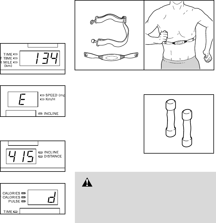
The Time/Pace display
will show the total number
of hours that the treadmill
has been used.
An E, for English miles, or
an M, for metric kilome-
ters, will appear in the
Speed/Pace display.
Press the Speed
▲▲
button
to change the unit of mea-
surement.
The Incline/Distance
display will show the total
number of miles that the
walking belt has moved.
IMPORTANT: The
Calories/Pulse display
should be blank. If a “d”
appears in the display,
the console is in the
“demo” mode. This mode
is intended to be used only when a treadmill is dis-
played in a store. When the console is in the demo
mode, the power cord can be plugged in, the key can
be removed from the console, and the displays and in-
dicators on the console will automatically light in a pre-
set sequence, although the buttons on the console will
not operate. If a “d” appears in the Calories/Pulse
display when the information mode is selected,
press the Speed
▼▼
button so the Calories/Pulse
display is blank.
To exit the information mode/demo mode, remove the
key from the console.
THE OPTIONAL CHEST PULSE SENSOR
An optional chest pulse sensor adds even more
features to the console. The chest pulse sensor provides
hands-free operation and continuously monitors your
heart rate during your workouts. To purchase the
optional chest pulse sensor, call toll-free 1-800-
734-2377.
OPTIONAL HAND WEIGHTS
Optional hand weights
let you exercise your
upper body while you
walk on the treadmill.
The hand weights fit
into convenient holders
in the console. To pur-
chase hand weights,
call toll-free 1-800-
772-0257.
WARNING: Using hand weights
and not holding the handrails may compro-
mise your ability to maintain your balance.
Hand weights should be used only by experi-
enced users.
22
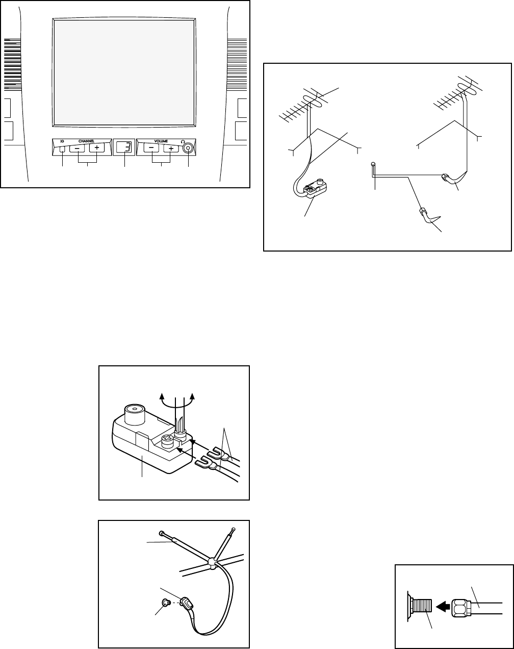
DIAGRAM OF THE TELEVISION
1. Power button
2. Channel + and – buttons
3. Channel display
4. Volume + and – buttons
5. Earphone/Headphone jack
ANTENNA CONNECTIONS
Indoor Antenna
1. Place the VHF
antenna in the
desired loca-
tion. Connect
the 300 ohm
flat wire to the
screws on the
300 ohm to 75
ohm adapter.
2. Connect the
300 to 75 ohm
adapter to the
75 ohm an-
tenna terminal
on the treadmill.
(See assembly
drawing 7 on
page 8 to find
the location of
the terminal.)
Outdoor Antenna
Outdoor antennas are subject to weathering that can
reduce signal quality. Inspect the antenna and lead-in
wiring before connecting the antenna. Any service cen-
ter can explain the various outdoor antennas available.
300 Ohm Flat Wire
1. See the drawing above. Connect the 300 ohm flat
wire to the 300 ohm to 75 ohm adapter.
2. Push the end of the 300 ohm to 75 ohm adapter into
the 75 ohm antenna terminal on the treadmill. (See
assembly drawing 7 on page 8 to find the location of
the terminal.)
75 Ohm Coaxial Cable
See the drawing above. Connect the 75 ohm coaxial
cable directly to the 75 ohm antenna terminal on the
treadmill. (See assembly drawing 7 on page 8 to find
the location of the terminal.)
CATV CABLE CONNECTION
1. Remove the VHF 300 to 75 ohm adapter or the VHF
cable from the antenna terminal on the treadmill. (See
assembly drawing 7 on page 8 to find the location of
the terminal.)
2. Connect the CATV
cable (75 ohm coaxial
cable) to the 75 ohm
antenna terminal on
the treadmill.
1235
300 to 75 Ohm Adapter
Screwdriver
VHF 300
Ohm Flat
Wire
75 Ohm
Terminal
300 to 75 Ohm
Adapter
VHF Rod
Antenna
4
Combination
VHF/UHF Antennas
300 Ohm
Flat Wire
75 Ohm
Terminal
on Treadmill
300 to 75
Ohm Adapter
75 Ohm
Coaxial Cable
75 Ohm CATV Cable
VHF 75 Ohm Jack
75 Ohm CATV Cable
BASIC TELEVISION OPERATION
Insert the key fully into the console.
See GETTING STARTED on page 11.
Press the Power button below the television to
turn on the television.
When the button is
pressed, the channel
display will light and
show the most re-
cently selected
channel.
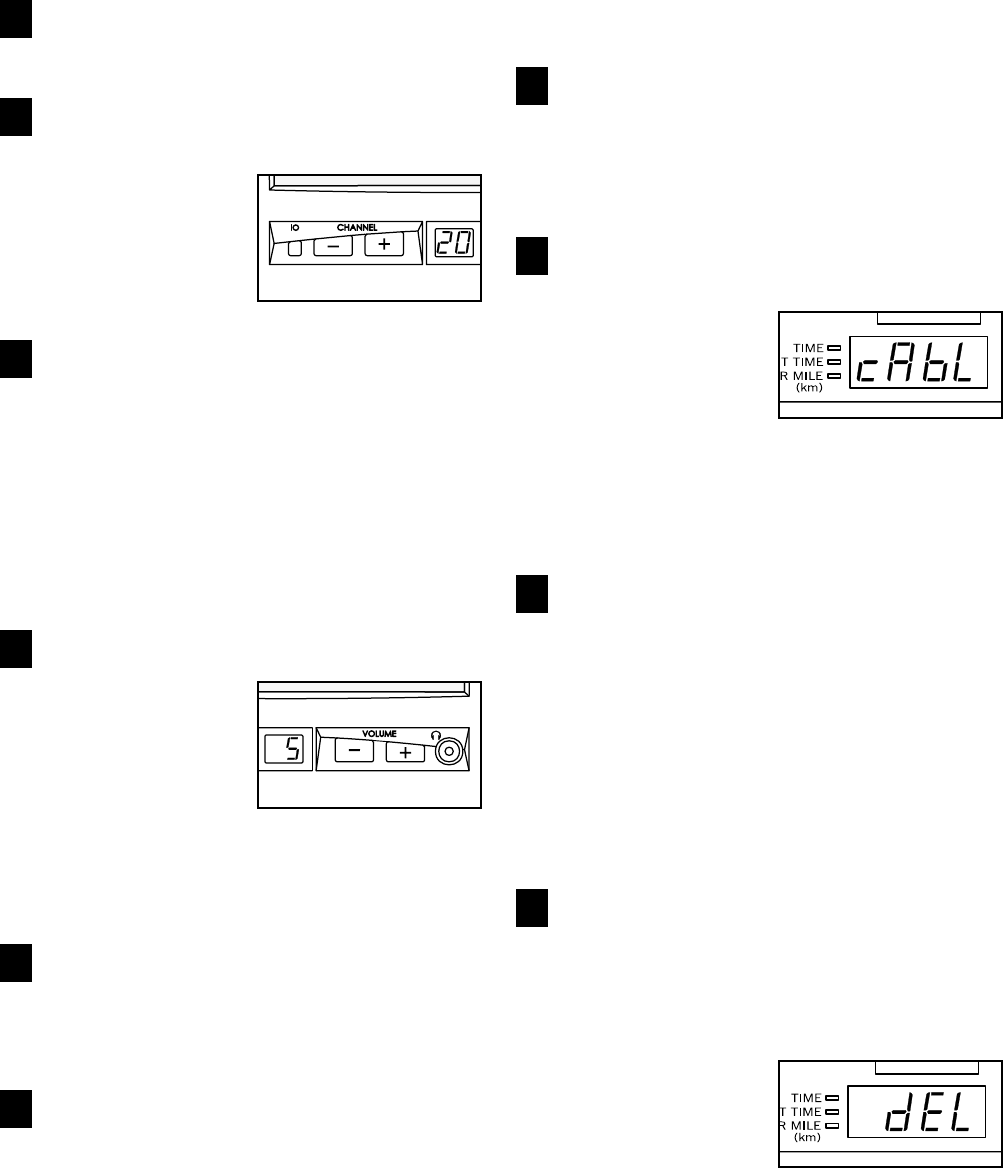
Press the Channel buttons to select the
desired channel.
To change the channel, press the Channel but-
tons. Note: The television is equipped with a
channel memorizing function that allows you to
step up or down from the current channel to the
next channel set into memory. Before channels
can be selected in this way, they must be set into
the television’s memory. See HOW TO MEMO-
RIZE CHANNELS at the right.
Press the Volume buttons to adjust the volume.
When the Volume
buttons are pressed,
the selected volume
level will appear in
the channel display
for a few seconds.
There are 11 volume
levels (0 though 10). Note: To use earphones or
headphones (not included), plug them into the
jack below the console.
When you are finished using the television,
press the Power button below the television.
When the button is pressed, the channel display
will darken.
When you are finished using the treadmill, re-
move the key.
Remove the key from the console and put it in a
secure place. Next, move the on/off switch near
the power cord to the off position and unplug the
power cord.
HOW TO MEMORIZE CHANNELS
Follow the steps below to set channels into the televi-
sion’s memory.
Press the Stop button while inserting the key
fully into the console.
The console will turn on and the information mode/
demo mode will be selected. (See THE INFOR-
MATION MODE/DEMO MODE on page 21.)
Press the Stop button and set the television for
a cable connection or an antenna connection.
When the button is
pressed, the letters
cAbL (cable) or Air
will appear in the
Time/Pace display. If
you have connected
a CATV cable to the treadmill, cAbL should be se-
lected. If you have connected an antenna, Air
should be selected. Press the Power button below
the television to change the setting, if necessary.
Press the Channel + button to scan and
memorize channels.
When the button is pressed, the television will
begin scanning all of the channels available in
your area. When no broadcast signal is detected
on a channel, the channel will be skipped. When a
signal is detected, the channel will be stored in
memory, a tone will sound, and the next channel
will be selected. This process will be repeated
until the highest channel is reached. A series of
tones will then sound.
Press the Stop button and erase or add
channels.
After all valid channels available in your area have
been set into memory, you can erase unwanted
channels or manually add channels.
To erase a channel,
first press the
Channel buttons until
the unwanted chan-
nel appears in the
channel display. The
letters dEL (delete) will appear in the Time/Pace
display. Press the Power button below the televi-
sion to delete the channel.
4
3
2
1
6
5
4
3
2
1
24
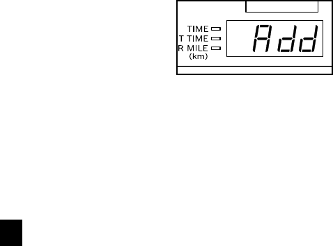
To add a channel,
first press the
Channel buttons
until the desired
channel appears in
the channel display.
The word Add will appear in the Time/Pace dis-
play. Press the Power button below the television
to add the channel.
Repeat this procedure to delete or add as many
channels as desired.
Remove the key from the console.
When the key is removed, the information mode/
demo mode will be exited.
HOW TO CONNECT A VCR
Follow the steps below to connect your VCR (not in-
cluded) to the treadmill. A CATV cable (75 ohm coaxial
cable) at least nine feet long is required.
1. Connect one end of the CATV cable to the video
output jack on your VCR.
2. Plug in the power cord of your VCR. See your VCR
user’s manual for proper grounding instructions.
3. Connect the CATV cable to the 75 ohm antenna ter-
minal on the treadmill. (See assembly drawing 7 on
page 8 to find the location of the terminal.
To operate the television with your VCR, refer to
BASIC TELEVISION OPERATION on page 23. Make
sure that channel 3 or 4 is selected.
5
HOW TO FOLD AND MOVE THE TREADMILL
HOW TO FOLD THE TREADMILL FOR STORAGE
Before folding the treadmill, adjust the incline to the
lowest position. If this is not done, the treadmill may be per-
manently damaged. Remove the key and unplug the power
cord. CAUTION: You must be able to safely lift 45 pounds
(20 kg) in order to raise, lower, or move the treadmill.
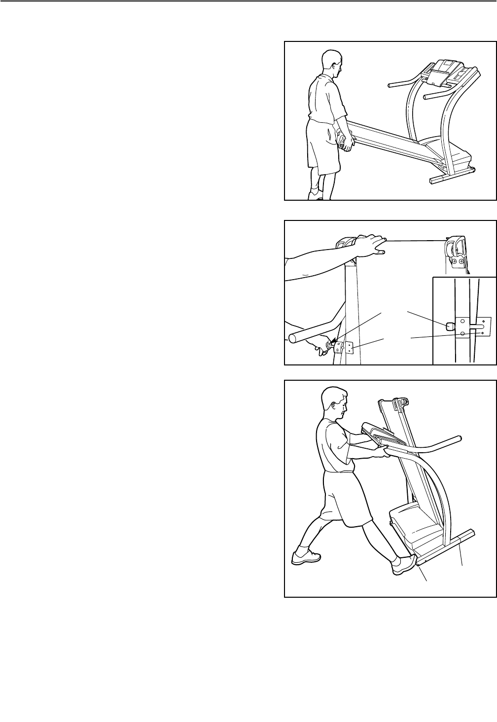
1. Hold the treadmill with your hands in the locations shown
at the right. CAUTION: To decrease the possibility of in-
jury, bend your legs and keep your back straight. As
you raise the treadmill, make sure to lift with your legs
rather than your back. Raise the treadmill about halfway
to the vertical position.
2. Move your right hand to the position shown and hold the
treadmill firmly. Using your left hand, pull the lock knob to
the left and hold it. Raise the treadmill until the lock pin is
aligned with the catch plate. Make sure that the pin is
resting on the plate as shown.
To protect the floor or carpet from damage, place a
mat under the treadmill. Keep the treadmill out of
direct sunlight. Do not leave the treadmill in the stor-
age position in temperatures above 85° Fahrenheit.
HOW TO MOVE THE TREADMILL
Before moving the treadmill, convert the treadmill to the stor-
age position as described above. Make sure that the pin is
resting on the plate.
1. Hold the handrails as shown and place one foot against a
wheel.
2. Tilt the treadmill back until it rolls freely on the front wheels.
Carefully move the treadmill to the desired location. Never
move the treadmill without tipping it back. To reduce
the risk of injury, use extreme caution while moving
the treadmill. Do not attempt to move the treadmill
over an uneven surface.
3. Place one foot on wheel, and carefully lower the treadmill
until it is resting in the storage position.
HOW TO LOWER THE TREADMILL FOR USE
1. Refer to drawing 2 above. Hold the upper end of the treadmill with your right hand as shown. Using your left
hand, pull the lock knob to the left and hold it. Pivot the treadmill down until the frame is past the pin on the
lock knob.
2. Refer to drawing 1 above. Hold the treadmill firmly with both hands, and lower the treadmill to the floor. Do not
drop the treadmill. CAUTION: To decrease the possibility of injury, bend your legs and keep your back
straight.
Base
Front Wheels
Knob
Plate
TROUBLE-SHOOTING
Most treadmill problems can be solved by following the instructions below. If further assistance is
needed, please call our Customer Service Department toll-free at 1-800-999-3756, Monday through Friday,
6 a.m. until 6 p.m. Mountain Time (excluding holidays).
PROBLEM: The power does not turn on
SOLUTION: a. Make sure that the power cord is plugged into a surge suppressor, and that the surge suppressor
is plugged into a properly grounded outlet (see page 9). Use only a single-outlet surge suppressor
that meets all of the specifications described on page 9. Important: The treadmill is not compatible
with GFCI-equipped outlets.
b. After the power cord has been plugged in, make sure that the key is fully inserted into the console.
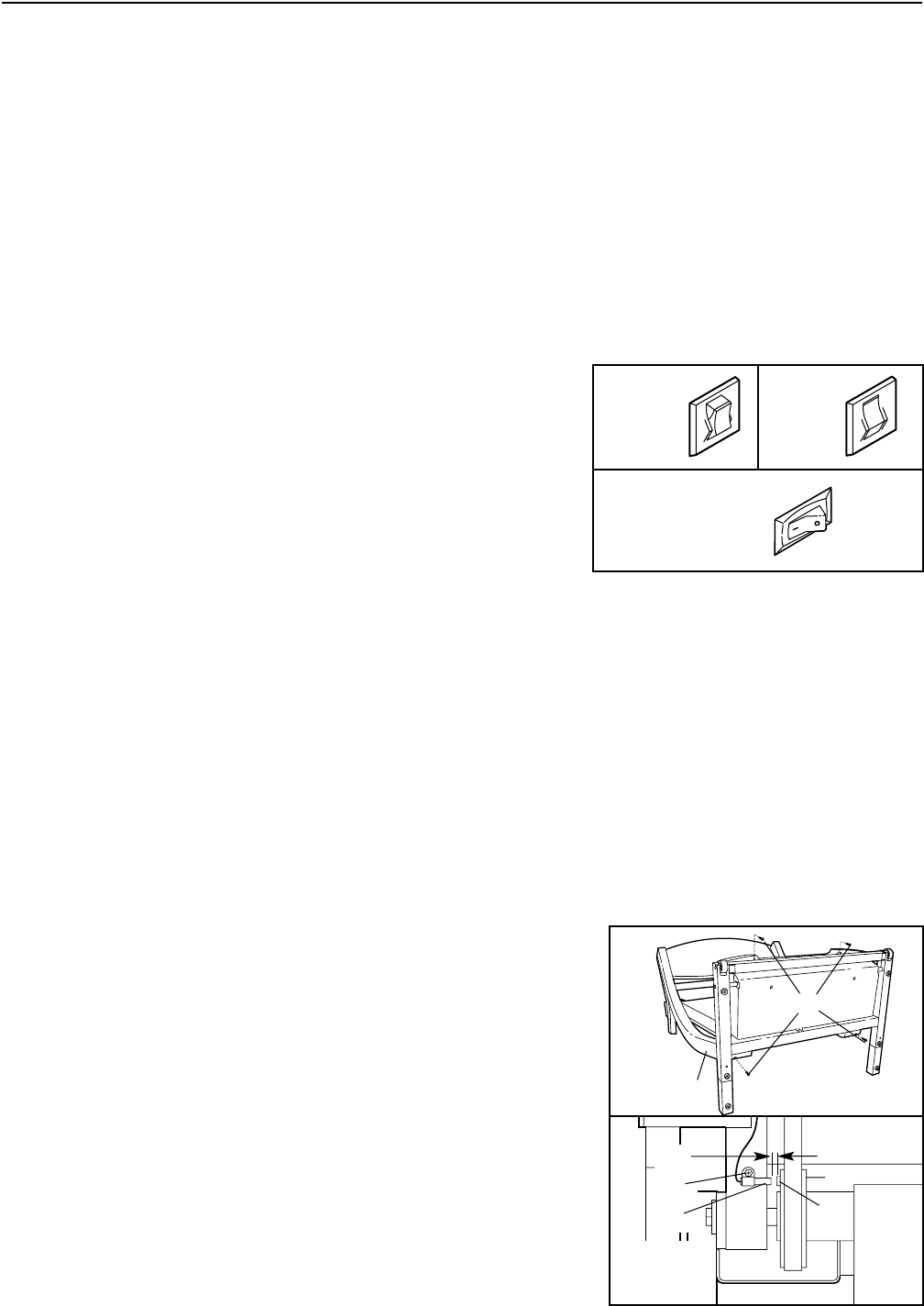
c. Check the circuit breaker located on the treadmill
near the power cord. If the switch protrudes as
shown, the circuit breaker has tripped. To reset the
circuit breaker, wait for five minutes and then press
the switch back in.
d. Check the on/off switch located on the treadmill
near the power cord. The switch must be in the on
position.
PROBLEM: The power turns off during use
SOLUTION: a. Check the circuit breaker located on the treadmill frame near the power cord (see c. above). If the
circuit breaker has tripped, wait for five minutes and then press the switch back in.
b. Make sure that the power cord is plugged in.
c. Unplug the power cord, wait for five minutes, and then plug the power cord back in.
d. Remove the key from the console. Reinsert the key fully into the console.
e. Make sure that the on/off switch is in the on position.
f. If the treadmill still will not run, please call our Customer Service Department, toll-free.
PROBLEM: The displays of the console do not function properly
SOLUTION: a. Remove the key from the console and unplug the
power cord. Carefully tip the treadmill down as shown
in drawing a. Remove the Screws (66) from the hood.
Raise the Uprights (110) and carefully remove the
hood.
Locate the Reed Switch (35) and the Magnet (30) on
the left side of the Pulley (29). Turn the Pulley until the
Magnet is aligned with the Reed Switch. Make sure
that the gap between the Magnet and the Reed
Switch is about 1/8”. If necessary, loosen the Screw
(49) and move the Reed Switch slightly. Retighten the
Screw. Re-attach the hood, and run the treadmill for a
few minutes to check for a correct speed reading.
Tripped
c
Reset
30
110
a
29
Top
View
49
1/8”
35
On
Position
d
66
26
PROBLEM: The walking belt slows when walked on
SOLUTION: a. Use only a single-outlet surge suppressor that meets all of the specifications described on page 8.
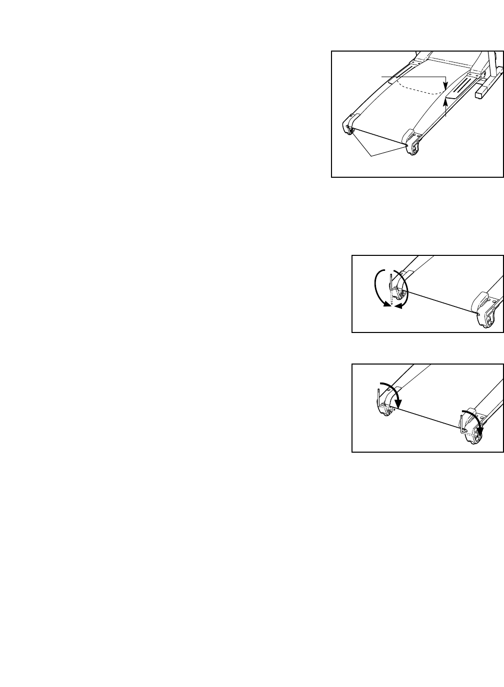
b. If the walking belt is overtightened, treadmill perfor-
mance may decrease and the walking belt may be-
come damaged. Remove the key and UNPLUG THE
POWER CORD. Using the allen wrench, turn both
rear roller adjustment bolts counterclockwise, 1/4 of a
turn. When the walking belt is properly tightened, you
should be able to lift each side of the walking belt 3 to
4 inches off the walking platform. Be careful to keep
the walking belt centered. Plug in the power cord, in-
sert the key and run the treadmill for a few minutes.
Repeat until the walking belt is properly tightened.
c. If the walking belt still slows when walked on, please call our Customer Service Department, toll-
free.
PROBLEM: The walking belt is off-center or slips when walked on
SOLUTION: a. If the walking belt has shifted to the left, first remove
the key and UNPLUG THE POWER CORD. Using the
allen wrench, turn the left rear roller bolt clockwise 1/2 of a
turn. Be careful not to overtighten the walking belt. If the
walking belt has shifted to the right, turn the left rear
roller bolt counterclockwise 1/2 of a turn. Plug in the power
cord, insert the key and run the treadmill for a few minutes.
Repeat until the walking belt is centered.
b. If the walking belt slips when walked on, first remove the
key and UNPLUG THE POWER CORD. Using the allen
wrench, turn both rear roller bolts clockwise, 1/4 of a turn.
When the walking belt is correctly tightened, you should
be able to lift each side of the walking belt 3 to 4 inches off
the walking platform. Be careful to keep the walking belt
centered. Plug in the power cord, insert the key and care-
fully walk on the treadmill for a few minutes. Repeat until
the walking belt is properly tightened.
PROBLEM: The incline of the treadmill does not change correctly or does not change when iFIT.com
CDs and videos are played
SOLUTION: a. With the key in the console, press one of the Incline buttons. While the incline is changing, re-
move the key. After a few seconds, re-insert the key. The treadmill will automatically rise to the
maximum incline level and then return to the minimum level. This will recalibrate the incline sys-
tem.
Rear Roller Adjustment Bolts
3”–4”
b
a
b

28
PROBLEM: Television reception is poor
SOLUTION: a. For the television to operate properly, good reception is necessary. If you are using an antenna,
make sure that it is properly connected and adjusted for optimal reception. (See ANTENNA CON-
NECTIONS on page 22.)
b. Check for the problems listed below and follow the applicable instructions.
• Ignition (black spots or horizontal streaks that appear or a picture that flutters or drifts)—Usually
this is caused by interference from automobile ignition systems, neon lamps, electric drifts, or
other electric appliances. Try changing the position of the treadmill or other electric appliances
to correct the problem.
• Ghosts—Ghosts are caused by the television signal following two paths—one is the direct path
and the other is reflected from tall buildings, hills, or other objects. Change the direction or posi-
tion of the antenna to improve reception.
• Snow—If the treadmill is located in the fringe area of a television station where the signal is
weak, the picture may be marred by the appearance of small dots. If the signal is weak, it may
be necessary to install an external antenna to improve the picture.
Note: If one of these symptoms appears when the cable from a CATV company is connected, the
symptom may be caused by the local company broadcast.
CONDITIONING GUIDELINES
The following guidelines will help you to plan your ex-
ercise program. For more detailed exercise informa-
tion, obtain a reputable book or consult your physician.
EXERCISE INTENSITY
Whether your goal is to burn fat or to strengthen your
cardiovascular system, the key to achieving the
desired results is to exercise with the proper intensity.
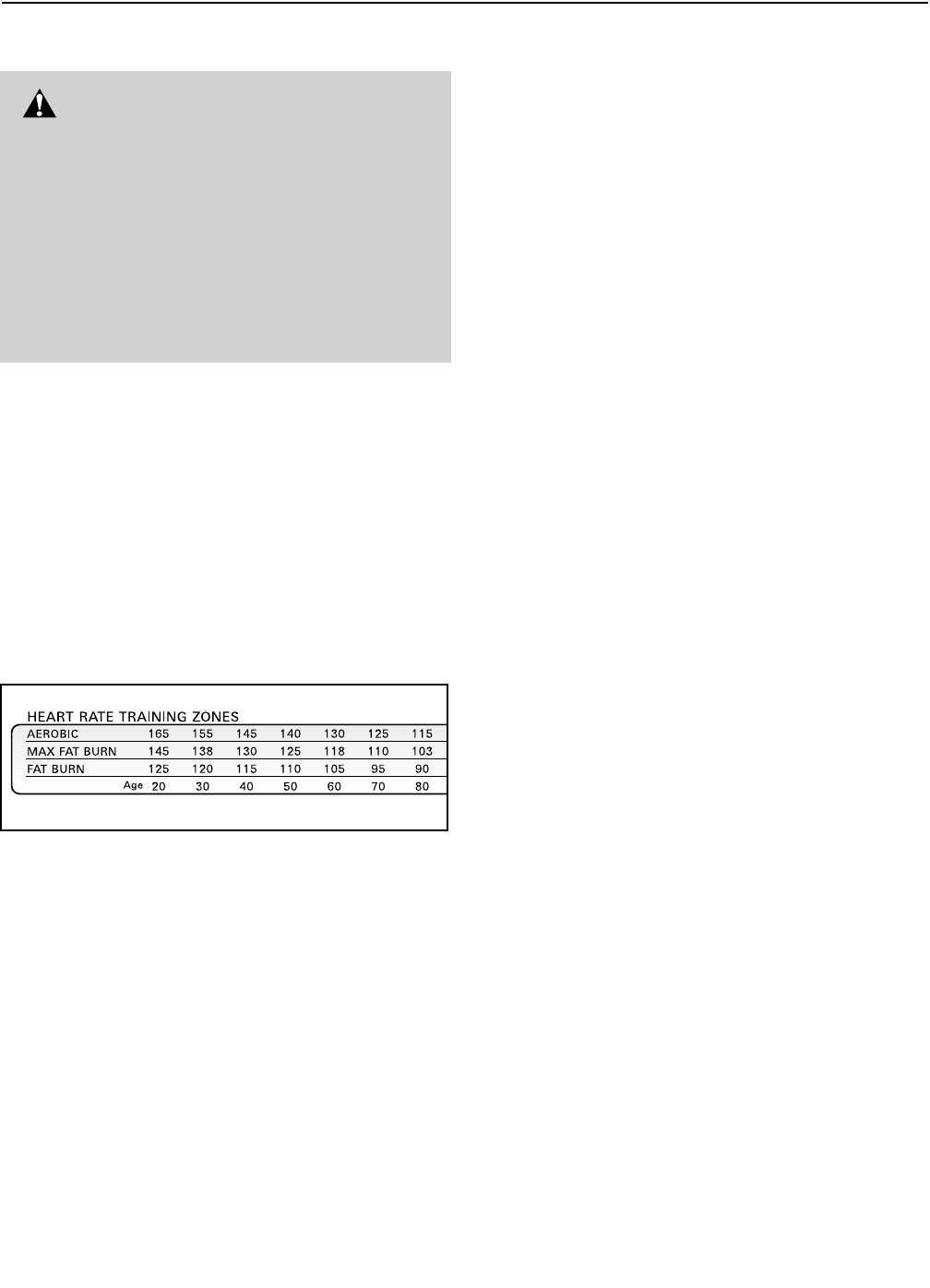
The proper intensity level can be found by using your
heart rate as a guide. The chart below shows recom-
mended heart rates for fat burning and aerobic exercise.
To find the proper heart rate for you, first find your age
near the bottom of the chart (ages are rounded off to
the nearest ten years). Next, find the three numbers
above your age. The three numbers define your “train-
ing zone.” The lower two numbers are recommended
heart rates for fat burning; the highest number is the
recommended heart rate for aerobic exercise.
To measure your heart rate during exercise, use the
handgrip pulse sensor or the optional chest pulse sen-
sor (see page 21). If your heart rate is too high or too
low, adjust the speed and incline of the treadmill.
Fat Burning
To burn fat effectively, you must exercise at a relatively
low intensity level for a sustained period of time.
During the first few minutes of exercise, your body
uses easily accessible carbohydrate calories for en-
ergy. Only after the first few minutes does your body
begin to use stored fat calories for energy. If your goal
is to burn fat, adjust the speed and incline of the tread-
mill until your heart rate is near the lowest number in
your training zone.
For maximum fat burning, adjust the speed and incline
of the treadmill until your heart rate is near the middle
number in your training zone.
Aerobic Exercise
If your goal is to strengthen your cardiovascular sys-
tem, your exercise must be “aerobic.” Aerobic exercise
is activity that requires large amounts of oxygen for
prolonged periods of time. This increases the demand
on the heart to pump blood to the muscles, and on the
lungs to oxygenate the blood. For aerobic exercise,
adjust the speed and incline of the treadmill until your
heart rate is near the highest number in your training
zone.
WORKOUT GUIDELINES
Each workout should include the following three parts:
A Warm-up—Start each workout with 5 to 10 minutes
of stretching and light exercise. A proper warm-up in-
creases your body temperature, heart rate and circula-
tion in preparation for exercise.
Training Zone Exercise—After warming up, increase
the intensity of your exercise until your pulse is in your
training zone for 20 to 60 minutes. (During the first few
weeks of your exercise program, do not keep your
pulse in your training zone for longer than 20 minutes.)
Breathe regularly and deeply as you exercise—never
hold your breath.
A Cool-down—Finish each workout with 5 to 10 min-
utes of stretching to cool down. This will increase the
flexibility of your muscles and will help prevent post-ex-
ercise problems.
EXERCISE FREQUENCY
To maintain or improve your condition, complete three
workouts each week, with at least one day of rest be-
tween workouts. After a few months, you may com-
plete up to five workouts each week if desired.
The key to success is to make exercise a regular and
enjoyable part of your everyday life.
WARNING: Before beginning this
or any exercise program, consult your physi-
cian. This is especially important for individu-
als over the age of 35 or individuals with pre-
existing health problems.
The pulse sensor is not a medical device.
Various factors, including your movement,
may affect the accuracy of heart rate readings.
The sensor is intended only as an exercise aid
in determining heart rate trends in general.

PART LIST—Model No. HRTL13910 R0102A
To locate the parts listed below, refer to the EXPLODED DRAWING attached in the center of this manual.
Key No. Qty. Description Key No. Qty. Description
1 1 Allen Wrench
2 2 Wheel Bolt
3 1 Rear Endcap (Left)
4 2 Roller Adj. Washer
5 2 Rear Roller Adj. Washer
6 2 Rear Wheel
7 8 Front Wheel Nut/Frame Pivot Nut
8 8 Endcap Screw
9 1 Roller Guard (Left)
10 1 Roller Guard (Right)
11 1 Rear Endcap (Right)
12 1 Roller Ground Wire
13 1 Filter Wire
14 1 Rear Roller
15 1 Warning Decal
16 1 Latch Plate
17 2 Latch Plate Screw
18 2 Frame Pivot Bolt
19 1 Front Endcap (Left)
20 2 Belt Guide
21 1 Foot Grip (Left)
22 1 Walking Belt
23 1 Walking Deck
24 1 Foot Grip (Right)
25 1 Power Board
26 1 Front Endcap (Right)
27 2 Support Bracket Screw
28 1 Support Bracket
29 1 Front Roller/Pulley
30 1 Magnet
31 8 Console Screw (Long)
32 2 Washer
33 2 Frame Pivot Bushing
34 2 Frame Pivot Spacer
35 1 Reed Switch
36 1 Reed Switch Clip
37 1 iFIT.com Wire
38* 1 Motor Assembly
39 1 Flywheel/Pulley
40 1 Motor Belt
41 1 Motor Pivot Nut
42 3 Motor Tension Nut/Lift Frame Nut
43 1 Motor Tension Washer
44** 2 Optional Weights
45 1 Motor Pivot Bolt
46 1 Motor
47 1 Lift Frame
48 1 Motor Star Washer
49 10 Screw
50 1 Jack
51 1 Key/Clip
52 1 Incline Motor Bolt (Top)
53 8 Endcap Washer
54 1 Incline Motor Stop
55 8 Endcap Nut
56 1 Incline Motor Bolt (Bottom)
57 1 Incline Motor
58 1 Front Roller Bolt
59 4 Plastic Stand-off
60 1 Electronic Plate
61 1 Controller
62 1 Motor Controller Wire
63 1 Power Cord
64 1 Power Cord Grommet
65 1 On/Off Switch
66 2 Belly Pan Screw (Long)
67 1 Audio Wire Nut
68 1 Circuit Breaker
69 2 Static Decal
70 1 12” Audio Wire
71 1 Belly Pan
72 4 3/4” Screw
73** 1 Chest Pulse Sensor
74** 1 Chest Pulse Strap
75 3 Base Pad
76 1 Console Base
77 1 Book Holder
78 1 Console
79 2 Handrail Endcap
80 2 Pulse Grip
81 4 Pulse Grip Screw
82 4 Console Screw (Short)
83 1 Console Back
84* 2 Extension Leg Assembly
85 2 Extension Leg Endcap
86 12 Base Screw/Latch Screw
87 2 Incline Motor Spacer
88 2 Extension Leg
89 1 Handrail
90 4 Thick Base Pad
91 1 Motor Hood
92 1 8” Wire Tie
93 2 Cable Tie Clamp
94 1 Transformer
95 1 Releasable Tie
96 2 Lift Pivot Bolt
97 2 Front Wheel Bolt
98 2 Front Wheel
99 1 Incline Motor Guard
100 1 Upright Grommet
101 1 Upright Wire Harness
102** 2 Hand Weight
30

Key No. Qty. Description Key No. Qty. Description
103 1 Lift Frame Bushing
104 1 TV Cable
105 2 Upright Endcap
106 1 Left Handrail Spacer
107 1 Right Handrail Spacer
108 4 Handrail Washer
109 1 Latch Assembly
110 1 Upright
111 4 Handrail Bolt
112 1 TV Cable (Short)
113 1 Television
114 4 U-nuts
115 1 Transformer Wire (2 Wire)
116 1 Upright Ground Wire
117 1 Console Ground Wire
118 1 Transformer Wire (3 Wire)
# 1 12” Green Wire, 2 Ring
# 1 12” Green Wire, F/Ring
# 1 8” Green Wire, M/Ring
# 1 14” Blue Wire, 2F
# 1 4” Blue Wire, M/F
# 1 8” White Wire, M/F
# 1 4” Black Wire, 2F
# 1 User's Manual
* Includes all parts shown in box
**For information about the optional chest pulse sensor
and hand weights, see page 21
# These parts are not illustrated
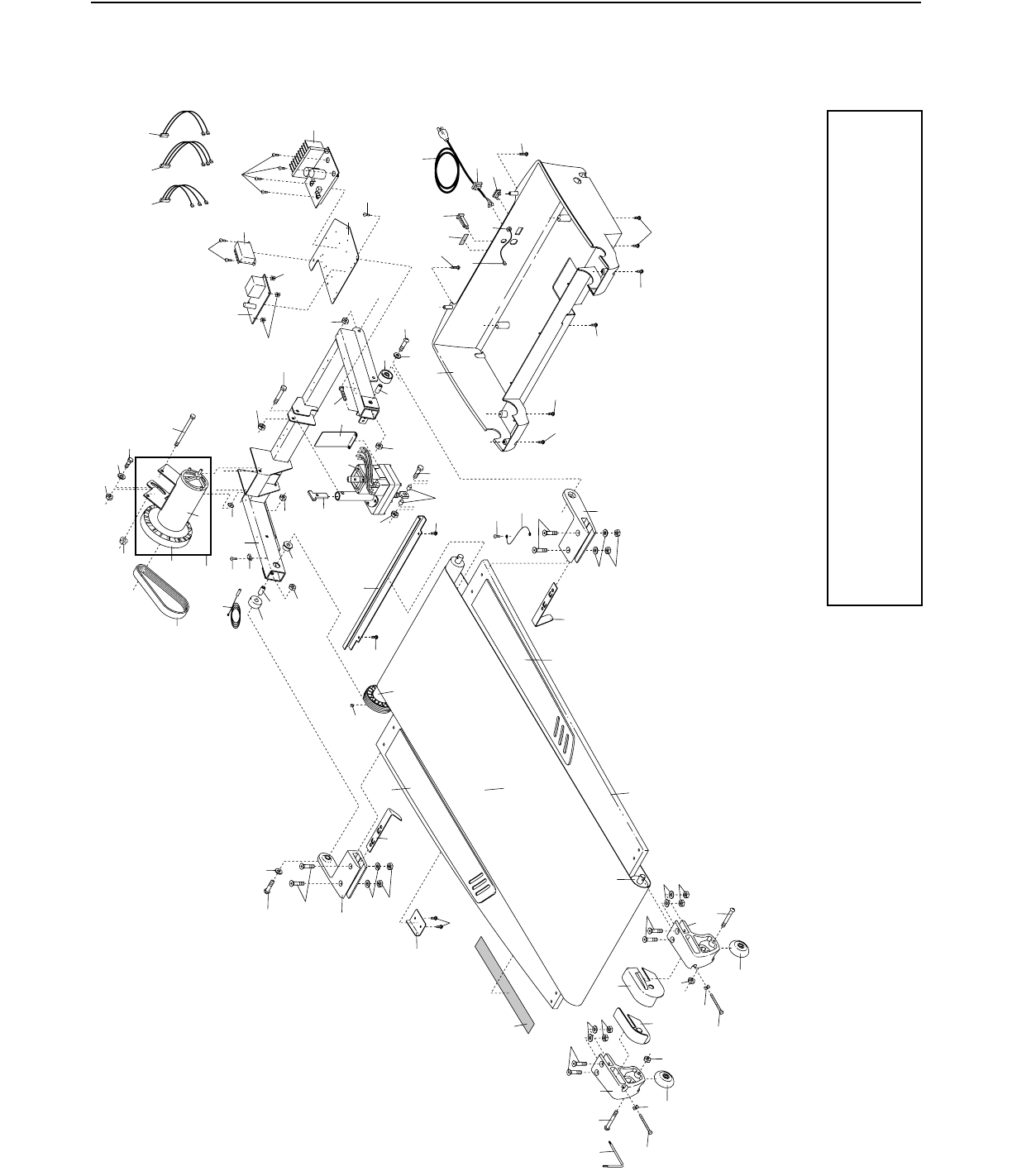
18
30
29
7
35
49
36 47 48
38*
40
46
39
41
42
56
45
59
25
59
60
49
7
58
733
18
7
54
57
42
56 71 66 69 68
63
65
66
72
72
66
49
12
1
64
70
72
66
43
62
67
15
20
52
7
28
27
27
20
26
16
17
19
21
22
24
14
2
11
6
5
4
10
9
6
3
8
8
54
34
34 33
23
2
77
8
8
53
55
53
55
53
55
53
55
32
32
87
99
49
61
103
49
94
118 115
EXPLODED DRAWING—Model No. HRTL13910 R0102A
To identify the parts shown on this exploded drawing, refer
to the PART LIST on pages 30 and 31 of the USER’S
MANUAL.
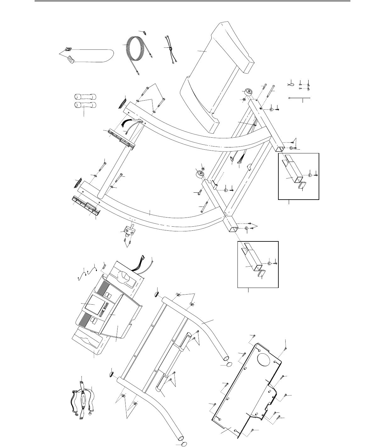
95
86
93
92
97
96
90
86
86
75
86
85
88
84*
90
86 100
101
7
98
97
96 91
86
89
79
80
80
81
81
79
108 111
105
105
107
106
110
102**
51
109
73**
74**
31
31
31
82
82
82
82
82
83
31
82
98
7
90
90
37
50
76
77
78
69
75
86
85
88
84*
13
113
108
111
108
111
79
79
117
116
112
104
104
114
114 86
EXPLODED DRAWING—Model No. HRTL13910 R0102A

Part No. 178748 R0102A Printed in USA © 2002 ICON Health & Fitness, Inc.
LIMITED WARRANTY
ICON Health & Fitness, Inc. (ICON), warrants this product to be free from defects in workmanship and
material, under normal use and service conditions, for a period of ninety (90) days from the date of pur-
chase. This warranty extends only to the original purchaser. ICON's obligation under this warranty is lim-
ited to replacing or repairing, at ICON's option, the product through one of its authorized service centers.
All repairs for which warranty claims are made must be pre-authorized by ICON. This warranty does not
extend to any product or damage to a product caused by or attributable to freight damage, abuse, misuse,
improper or abnormal usage or repairs not provided by an ICON authorized service center, products used
for commercial or rental purposes, or products used as store display models. No other warranty beyond
that specifically set forth above is authorized by ICON.
ICON is not responsible or liable for indirect, special or consequential damages arising out of or in con-
nection with the use or performance of the product or damages with respect to any economic loss, loss of
property, loss of revenues or profits, loss of enjoyment or use, costs of removal, installation or other con-
sequential damages of whatsoever nature. Some states do not allow the exclusion or limitation of inci-
dental or consequential damages. Accordingly, the above limitation may not apply to you.
The warranty extended hereunder is in lieu of any and all other warranties and any implied warranties of
merchantability or fitness for a particular purpose is limited in its scope and duration to the terms set forth
herein. Some states do not allow limitations on how long an implied warranty lasts. Accordingly, the
above limitation may not apply to you.
This warranty gives you specific legal rights. You may also have other rights which vary from state to state.
ICON HEALTH & FITNESS, INC., 1500 S. 1000 W., LOGAN, UT 84321-9813
HOW TO ORDER REPLACEMENT PARTS
To order replacement parts, call our Customer Service Department toll-free at 1-800-999-3756, Monday through
Friday, 6 a.m. until 6 p.m. Mountain Time (excluding holidays). To help us assist you, please be prepared to give
the following information:
• The MODEL NUMBER of the product (HRTL13910)
• The NAME of the product (HealthRider®T90 treadmill)
• The SERIAL NUMBER of the product (see the front cover of this manual)
• The KEY NUMBER and DESCRIPTION of the part(s) (see the PART LIST on pages 30 and 31).
