Hearth and Home Technologies CDR2F Electric Room Heater User Manual SFE 26 pub
Hearth & Home Technologies Electric Room Heater SFE 26 pub
Users Manual
1
4050-308 Rev A 9/13/2007
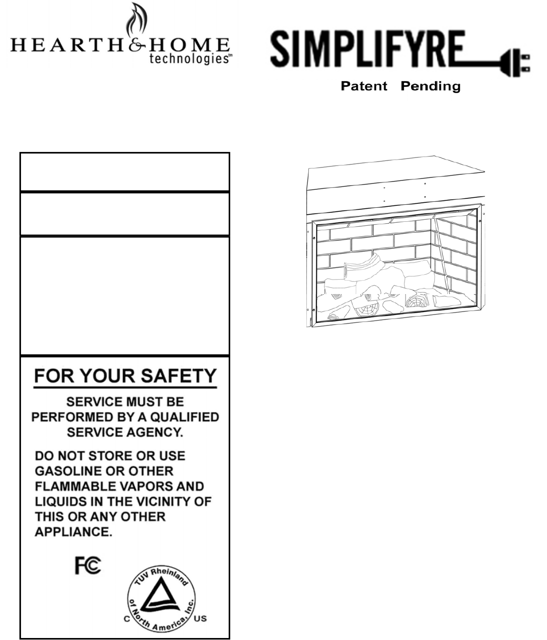
MODEL: SFE-26
BUILDER BOX
INSTALLER / CONSUMER
SAFETY INFORMATION
PLEASE READ THIS MANUAL
BEFORE INSTALLING AND
USING APPLIANCE
WARNING
IF THE INFORMATION IN THIS
MANUAL IS NOT FOLLOWED
EXACTLY, AN ELECTRICAL
SHOCK OR FIRE MAY RESULT,
CAUSING PROPERTY DAMAGE,
PERSONAL INJURY OR LOSS
OF LIFE TUV LISTED AS SFE-26
Homeowner’s Installation &
Operating Manual
NOTE: The device complies with Part 15 of the FCC Rules.
Operation is subject to the following two conditions:
1. This device may not cause harmful
interference, and
2. This device must accept any interference
received, including interference that may cause
undesired operation.
ANSI / UL 2021. FIXED OR LOCATION DEDICATED ELECTRIC ROOM HEATER.
INSTALLER: DO NOT DISCARD THIS MANUAL— LEAVE FOR HOME OWNER
SAVE THESE INSTRUCTIONS FOR FUTURE REFERENCE.
2
4050-308 Rev A 9/13/2007
Congratulations!
Congratulations on selecting a Simplifyre electric fireplace. The unit you have selected is designed to provide the
utmost in safety, reliability and efficiency.
As the owner of a new fireplace, you’ll want to read and carefully follow all of the instructions contained in this
owner’s manual. Pay special attention to all cautions and warnings.
This owner’s manual should be retained for future reference. We suggest you keep it with your other important
documents and product manuals.
The information contained in this owner’s manual unless noted otherwise, applies to all models.
Your new Simplifyre electric fireplace will give you years of durable use and trouble-free enjoyment.
Welcome to the Hearth & Home Technologies family of fireplace products!
TABLE OF CONTENTS
PLEASE READ THE INSTALLATION & OPERATION INSTRUCTIONS BEFORE
USING THIS APPLIANCE.
Important Instructions 3
Unpacking 4
Locating Your Electric Fireplace 4
Clearance to Combustibles 4
Electrical Specifications 4
Framing 4
Hardwire Electrical Connections 4
Optional-Wall switch/Thermostat 4
Finishing 4
Framing Dimensions 5
Operating Instructions 6
Remote Control Initialization 6
Electrical Wiring Diagram 7
Service Instructions 7
Replacing the Light Bulb 7
Screen Cleaning 7
Maintenance of Motors 7
Replacement Parts
Replacement Parts List 8
Warranty 9
3
4050-308 Rev A 9/13/2007
When using electrical heaters, basic precautions should
always be followed to reduce the risk of fire, electric shock
and injury to persons, including the following:
• Read all instructions before using this heater.
• This heater is hot when in use. To avoid burns, do not let
bare skin touch hot surfaces. If provided, use handles
when moving this heater. Keep combustible materials,
such as furniture, pillows, bedding, papers, clothes and
curtains away from sides and rear of heater, and at
least 36 in. (914 mm) from the front.
• Extreme caution is necessary when any heater is used
by or near children or invalids and whenever the heater
is left operating and unattended.
• Always unplug heater when not in use.
• Do not operate any heater with a damaged cord or plug
or after the heater malfunctions, has been dropped or
damaged in any manner. Return heater to authorized
service facility for examination, electrical or mechanical
adjustment, or repair.
• Do not use outdoors.
• This heater is not intended for use in bathrooms, laundry
areas and similar indoor locations. Never locate heater
where it may fall into a bathtub or other water container.
• Do not run cord under carpeting. Do not cover cord with
throw rugs, runners, or the like. Arrange cord away from
traffic areas and where it will not be tripped over. Do not
coil cord.
• To disconnect heater, turn controls to “OFF” then remove
plug from outlet.
• Do not insert or allow foreign objects to enter any
ventilation or exhaust opening as this may cause an
electric shock or fire, or damage the heater.
• To prevent a possible fire, do not block air intakes or
exhaust in any manner.
• An heater has hot and arcing or sparking parts inside. Do
not use it in areas where gasoline, paint, or flammable
liquids are used or stored.
• Use this heater only as described in this manual. Any
other use not recommended by the manufacturer may
cause fire, electric shock, or injury to persons.
• Always use properly grounded, fused and polarized
outlets.
• Always use ground fault protection where required by
electrical code.
• Always disconnect power before performing any
cleaning, maintenance or relocation of the heater.
• To prevent a possible fire, do not burn wood or other
materials in this heater.
• To prevent electric shock or fire, always use a certified
electrician should new circuits or outlets be required.
• When transporting or storing the heater, keep in a dry
place free from excessive vibration and store as to avoid
damage.
• SAVE THESE INSTRUCTIONS FOR FUTURE
REFERENCE.
• Changes or modification not expressly approved by the
party responsible for compliance could void the user’s
authority to operate the equipment.
IMPORTANT INSTRUCTIONS
4
4050-308 Rev A 9/13/2007
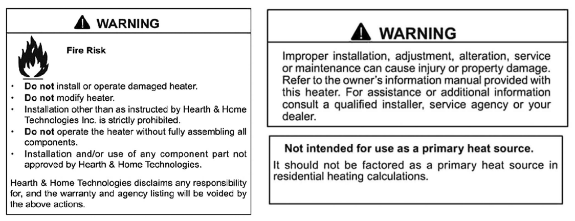
WARNING
Do not use this fireplace if any part of it has been
under water. Immediately call a qualified service
technician to inspect and replace any of the
electrical system if necessary.
Carefully remove packaging from the unit. The front
screen is held in place with four Phillips head
screws. To remove the screen, extract the screws.
Grasp the screen frame and pull out.
ELECTRICAL SPECIFICATIONS
Voltage: 120 V AC, 60 Hz
Total Amps: 11.25 AMP
Total Watts: 1350 Watts
Heater Rating: 1300 Watts/4415 BTU
LOCATING YOUR ELECTRIC FIREPLACE
Your new electric fireplace may be installed virtually
anywhere in your home. However, when choosing a
location ensure that the general instructions are
followed. For best results, install out of direct
sunlight.
Power supply service must be either completed or
placed within the heater prior to finishing to avoid
reconstruction.
Protective cover may stay on during framing, but
must be removed before final finishing. Once final
finishing has been completed, the protective cover
can be used to protect the heater until final
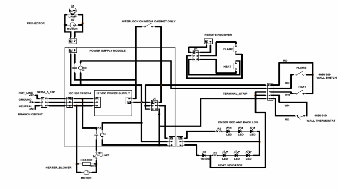
WARNING: Do NOT connect the optional low voltage switch
and/or thermostat to 120 volt branch circuit.
The Optional Wall Switch 4050-309 contains two single pole
switches. ( LEVITON 5634 Series or equal)
The Optional Wall Thermostat is a low voltage mechanical type.
( Columbus Electric RK120EAA or equal).
Maximum run distance is 30’ with 20 gauge solid copper low
voltage thermostat wire. Connect per the Electrical wiring
diagram on page 7.
WALL SWITCH AND THERMOSTAT CONNECTIONS
CLEARANCE TO COMBUSTIBLES
Sides……………………0 inches 0 mm
Floor……………...…….0 inches 0 mm
Top…………………......0 inches 0 mm
Back…………………….0 inches 0 mm
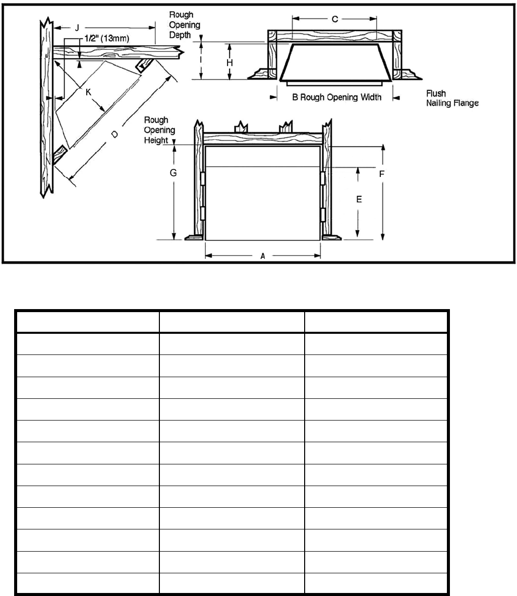
FRAMING
1. Choose a fireplace location and frame as shown in
fig. 1
2. Frame in the fireplace with a header across the top.
3. It is important to allow for finished face when setting
the depth of the frame.
4. If a hearth system or raised hearth is to be
installed, The unit MUST be raised to provide
service access and use of optional fronts.
5. The fireplace can now be positioned in the opening.
6. Level it with shims if necessary, and attach the unit
to the frame using the nailing flanges provided.
HARDWIRE ELECTRICAL CONNECTIONS
Electrical wiring must comply with local building codes and
other applicable regulations to reduce the risk of fire, electrical
shock and injury .
NOTE:
All wiring must be completed prior to finishing the unit.
For supply connections use No. 14 AWG or larger wires.
Use copper wire only. Connect only to a 15 AMP branch circuit.
A dedicated circuit is recommended as other appliances on the
circuit may cause the breaker to trip or fuse to blow when the
heater is operating.
1. Remove the screws securing the junction block cover.
2. Wire to a properly grounded, 120 volt, 60 Hz, 15 AMP circuit
3. Ensure all junction block connections are tight.
4. Replace the cover and retaining screws.
5. Plug in the IEC-320-C14 power plug to the IEC-320-C13
power inlet located on the upper right side of the unit.
6. All components and wiring may be inspected by removing
the top inter-panel through the fireplace front opening.
FINISHING
Combustible or non-combustible materials may be used to finish
up to the fireplace opening.
NOTE:
Ensure that you leave adequate room to remove and replace the
front screen or optional front.
UNPACKING THE UNIT
5
4050-308 Rev A 9/13/2007
FIREPLACE DIMENSIONS
Ref. inch cm
A 26 3/4 67.9
B 27 1/4 69.9
C 18 5/8 46.7
D 40 101.6
E 18 45.7
F 22 3/4 57.8
FRAMING DIMENSIONS
G 23 1/4 59.0
H 10 25.4
I 10 1/2 26.7
J 28 1/4 71.8
K 20 50.8
Fig. 1 FIREPLACE SPECIFICATIONS AND FRAMING DIMENSIONS
NOTE:
Provide allowance for
raised hearth or mantle.
This unit mounts flush to
the floor surface.
6
4050-308 Rev A 9/13/2007
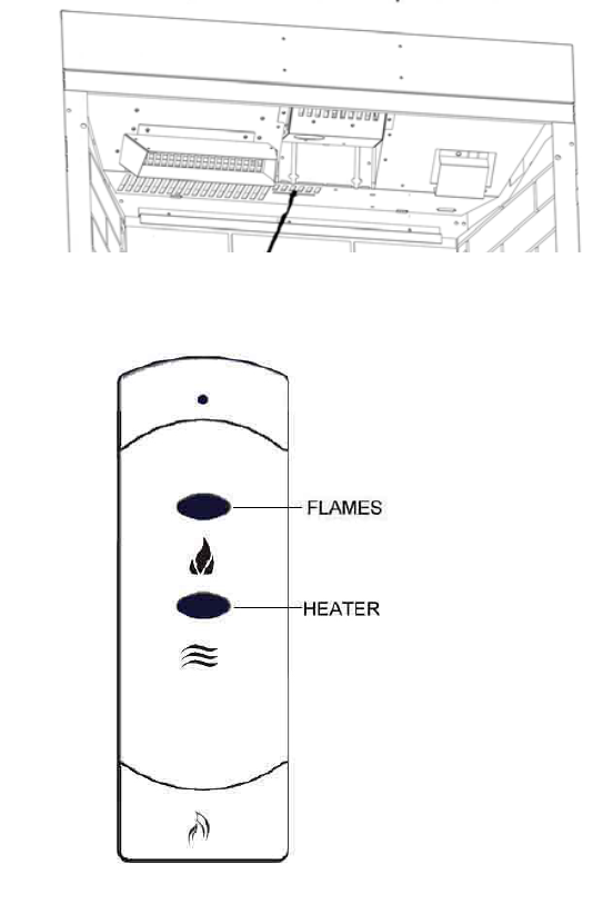
LEARN BUTTON
OPERATING INSTRUCTIONS
Ensure the appliance is connected to a properly grounded electrical outlet on a minimum 15 AMP circuit. If a new outlet is
required, it should be installed by a qualified electrician according to applicable building codes.
REMOTE CONTROL
NOTE: if the fireplace does not respond to the hand held control see “Remote Control Initialization” below.
This equipment has been tested and found to comply with the limits for Class B digital device, pursuant to Part 15 of the FCC
Rules. These limits are designed to provide reasonable protection against harmful interference in residential installation. This
equipment generates and uses, and can radiate radio frequency energy and , if not installed and u7sed in accordance with the
instructions, may cause harmful interference to radio communications. However, there is no guarantee that interference will not
occur in a particular installation. If this equipment does cause harmful interference to radio or television reception, which can be
determined by turning the equipment off and on, the user is encouraged to try to correct the interference by one or more of the
following measures:
• Re-orient or relocate the receiving antenna.
• Increase the separation between the equipment and receiver.
• Connect the equipment into an outlet on a circuit different from that to which the receiver is connected.
• Consult the dealer or an experienced radio/TV technician for help.
Remote Control Initialization
This procedure is required only when the unit is installed or the
transmitter is replaced and is not affected by the loss of power.
• Ensure that power is supplied through main service panel.
• Place fresh batteries in the transmitter.
• Access the learn button by removing the front screen.
• Press and hold down the learn button. You will hear a beep.
• Press a button on the hand-held transmitter.
• Release the learn button when you hear the long beep.
• This completes the remote control receiver/transmitter
initialization.
Control Usage
The remote control operates the fireplace modes.
• The flame effect and backlog/embers are turned ON/OFF by
alternate action of the FLAME button on the remote
transmitter.
• The heater/blower and front embers are turned ON/OFF by
alternate action of the HEATER button on the remote
transmitter.
• The optional wall FLAME switch provides manual operation
of the flame effect. On/Off
• The optional wall HEAT switch controls the front embers and
activates the optional remote wall thermostat.
• Set the thermostat to the desired room temperature.
The optional wall switches / thermostat are in parallel with the
remote control relays. The wall switches MUST be OFF for the
Remote Transmitter to control the fireplace.
NOTE: While the heater is ON the embers in front will glow.
Ensure the heater is OFF when unattended.
7
4050-308 Rev A 9/13/2007
WARNING
Disconnect power at circuit breaker before attempting any
maintenance or cleaning to reduce the risk of fire, electrical
shock or personal injury.
REPLACING THE LIGHT BULB
This appliance uses a single 12 Volt, 35 Watt, MR-16 bulb.
The bulb is located behind the smoke shield.
A spare is provided with the unit. Replacement bulbs (Part
No. 4050-123) are available through your Simplifyre dealer.
• Turn off power to the unit at the main service panel.
• Let the fireplace cool if it has been operating.
• Release the spring pins and remove the upper shield.
• Remove the two screws on the projector basket.
• Rotate the housing down to access the bulb.
• Remove the screws holding the bulb and socket.
• Unplug the bulb from the socket.
• Replace the bulb.
• Re-assemble in the reverse order.
SCREEN CLEANING
During shipment, installation, handling, etc., the
screen surface may collect dust particles; these can
be removed by lightly wiping with a clean, dry cloth.
MAINTENANCE OF MOTORS
The motors used on the fan and flame projector assembly
are pre-lubricated for extended bearing life and require no
further lubrication. However, periodic cleaning/vacuuming of
the fan/heater unit is recommended.
SERVICE INSTRUCTIONS
ELECTRICAL WIRING
1
5
Resetting the Temperature Cutout Switch
The heater on this fireplace is protected with a safety device
to prevent overheating. Should the heater overheat, an
automatic cutout will turn OFF the heater/blower. The switch
is reset by turning the unit OFF, waiting 10-15 minutes and
switching the unit back ON.
8
4050-308 Rev A 9/13/2007
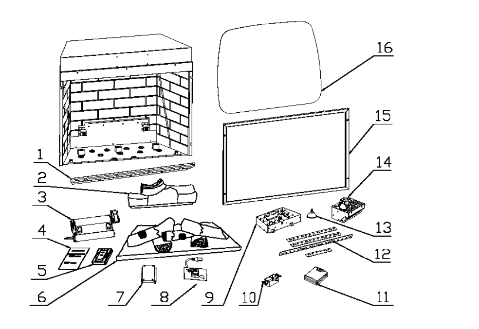
Replacement Parts List
1. Smoke Shield 4050-301
2. Back Log 4050-302
3. 120V Heater Assembly 4050-304
4. SFE-26 Installation Manual 4050-308
5. Remote Receiver 4050-108
6. Front Log/Emberbed Assembly 4050-300
7. Remote Transmitter 4050-105
8. Power Input Assembly 4050-005
9. Power Assembly 4050-305
10. Optional Wall Switch 4050-309
11. Optional Wall Thermostat 4050-310
12. LED Assembly 4050-306
13. Bulb 4050-123
14. Projector Assembly 4050-312
15. Front Screen Assembly 4050-307
16. Viewing Screen 4050-303
9
4050-308 Rev A 9/13/2007