Hearth and Home Technologies RC300 Remote Control Transmitter User Manual
Hearth & Home Technologies Remote Control Transmitter
User manual
Hearth & Home Technologies • RC300 Multifunction Remote Control • 2166-393 • 6/09 1
Installation & Operating Instructions
RC300
IntelliFire Plus™ Multifunction Remote Control
Hearth & Home Technologies disclaims any responsibility for,
and the warranty will be voided by, the following actions:
• Installation and use of any damaged system component.
• Modicationofthesystemcomponent.
• Installation other than as instructed by Hearth & Home
Technologies.
• Installation and/or use of any component part not approved
by Hearth & Home Technologies.
Any such action may cause a re hazard.
• Read, understand and follow these instructions for safe
installation and operation.
Introduction
The RC300 multifunctional remote controls is designed
to control pilot light, ame height, blower speed, and
up to two 110-120 VAC auxiliary functions on your gas
replace.TheRC300isequippedwiththermostatfunc-
tions which can automatically control the temperature
in the room in which it is installed. The control is only
for use with the Hearth & Home Technologies IntelliFire
Plus™ system (IPI). However, the pilot function can
controlthepilotameaswell.Electricalratingsforthe
control box are 120 VAC, 60 Hz, and is required for
operation of this device.
Installation Precautions
This remote control is tested and safe when installed in
accordance with this installation manual. Do not install
any components that may be damaged.
Do not modify, disassemble, or substitute any of the com-
ponents included with this kit. Installation of this unit must
bedonebyaqualiedservicetechnician.
Placement of this remote control may affect performance.
An assessment of the space should be done prior to in-
stallation for optimum performance.
Determine Location
Determine the location for the remote control. The selected
locationshouldbeinthesamespaceasthegasreplace.
Never place this unit in a separate room. The remote control
mustbeplacedwithin30feetofthereplacebutshould
not be exposed to extreme heat.
The RC300 is approved for interior installation and should
not be used in exterior applications.
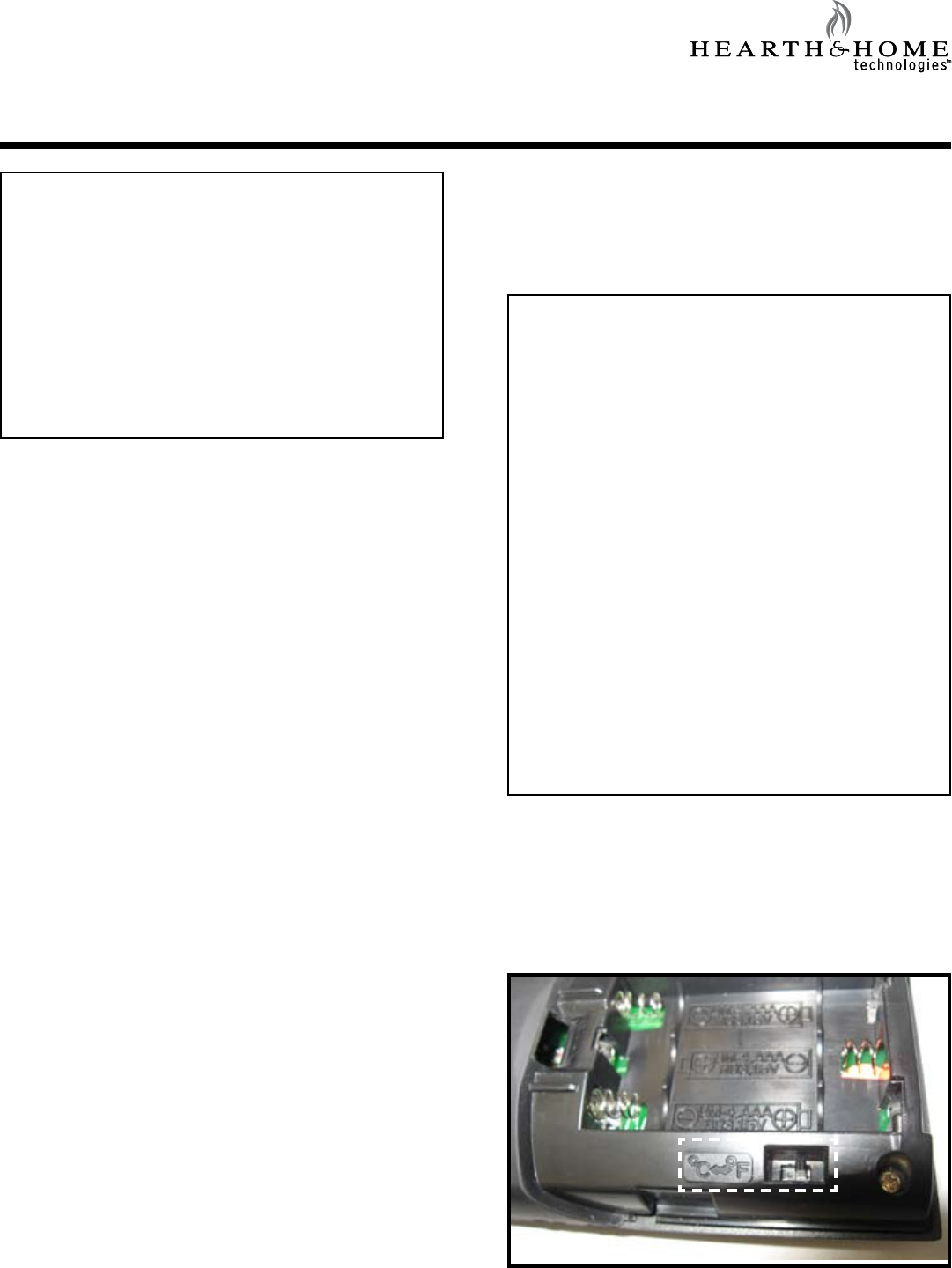
Figure 1. Temperature scale
Changing Temperature Scale
To change the temperature display between Celsius and
Fahrenheit, remove the battery cover from the back of the
remote control and slide the switch to your desired tem-
perature scale (see Figure 1). The screen will automati-
cally change the indicators on the room temperature and
set temperature portion.
FCC Requirements
WARNING! Risk of Fire! Changes or modications to
this unit not expressly approved by the party responsible
for compliance could void the user’s authority to operate
the equipment.
Note: Thisequipmenthasbeentestedandfoundto
comply with the limits for a Class B digital device, pur-
suant to Part 15 of the FCC Rules. These limits are
designed to provide reasonable protection against
harmful interference in a residential installation. This
equipment generates, uses, and can radiate radio
frequencyenergyand,ifnotinstalledandusedinac-
cordance with the instructions, may cause harmful in-
terference to radio communications. However, there is
no guarantee that interference will not occur in a partic-
ularinstallation.Ifthisequipmentdoescauseharmful
interference to radio or television reception, which can
bedeterminedbyturningtheequipmentoffandon,the
user is encouraged to try to correct the interference by
one or more of the following measures:
• Reorient or relocate the receiving antenna.
• Increasetheseparationbetweentheequipmentand
receiver.
• Connecttheequipmentintoanoutletonacircuitdif-
ferent from that to which the receiver is connected.
• Contact the dealer or an experienced radio TV techni-
cian for help.
Hearth & Home Technologies • RC300 Multifunction Remote Control • 2166-393 • 6/09
2
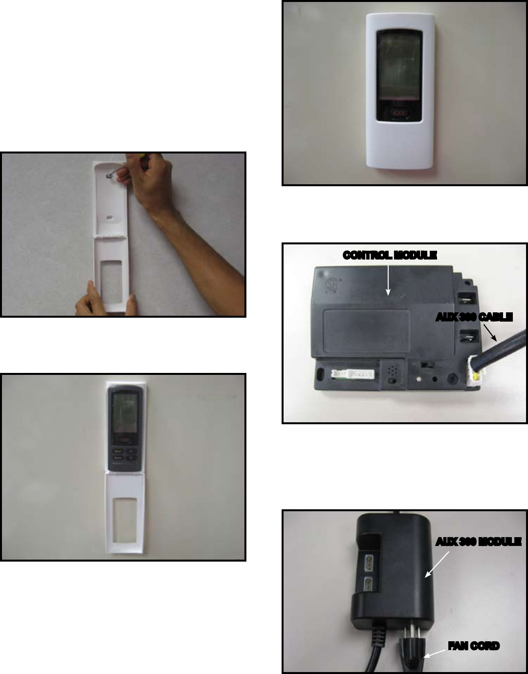
Figure 4. Mounting Remote Control Housing
5. Close the housing door. See Figure 4.
AUX300 Module Installation
• Insert the 4 hole harness from the AUX300 module into
the 4 pin plug on the control module. See Figure 5.
Fan Installation
• Insert the 3 prong plug from the fan into the receptacle
located in the AUX300 module. See Figure 6.
• Insert3prongplugfromAUX300moduleintoREM/AUX
receptacleofreplacejunctionbox.
Figure 6. Plug Fan into AUX300 Module
Figure 5. AUX 300 module installation
4. Place remote control inside housing. If batteries are
properly installed the remote will turn on See Figure 3.
Figure 3. Remote in Housing
Installation of Remote Control Housing
CAUTION! Risk of Fire! DO NOT install damaged or
modied components. Warranty will be voided if damaged
or modied components are installed.
Kit components: One remote control, two #6 screws, two
wall anchors, 3 AAA batteries and one AUX300 module.
1. Remove remote control components from packaging.
2. Remove battery cover from the back of the remote by
sliding it down and install 3 AAA batteries battery.
3.Securetheremotecontrolhousingonaatwallsur-
face using the two screws and wall anchors provided.
See Figure 2.
Figure 2. Mounting Remote Control Housing
CONTROL MODULE
AUX 300 CABLE
AUX 300 MODULE
FAN CORD
Hearth & Home Technologies • RC300 Multifunction Remote Control • 2166-393 • 6/09 3
TO JUNCTION
BOX (120V)
I
S
FLAME
SENSE IGNITER
3 PRONG 120VAC
RC300 4.5V DC
(AAA X 3)
TO JUNCTION
BOX 120VAC
TO OPTIONAL
COMPONENTS
GROUND
ORANGE
(PILOT)
GREEN
(MAIN)
BROWN
BLACK
RED
BROWN/RED
OPTIONAL ON/OFF
SWITCH
BATTERY PACK
6V DC (AA X 4)
FLAME
MODULATION
GROUND
AUX300 MODULE
AUX 1 AUX 2
FAN
WHITE
ORANGE
CONTROL MODULE
6V DC
SUPPLY
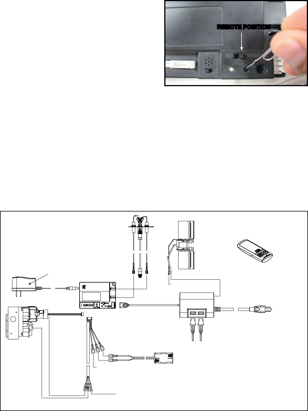
Figure 7. Programming RC300
REMOTE POSITION
Programming the RC300 to the Control Module
CAUTION! Risk of burns! DO NOT program the remote
control to the control module when replace is hot.
• VerifytheON/OFF/REMOTEswitchisintheREMOTE
position.GreenLEDlightwillblinktwiceandwallswitch
will beep twice. See Figure 7.
• Using a small item (such as a paper clip) press and
release the LEARN button located near the ON/OFF/
REMOTEswitch.SeeFigure7.
• ControlmodulewillbeeponceandLEDwillblinkgreen
for 10 seconds.
• WhiletheLEDisblinking,pressthePOWERbuttonon
the remote control. A double beep will come out of the
control module to indicate that it has been programmed
successfully.
NOTICE: Up to three remote controls can be programmed
into the control module. Simply press a button on the other
remote controls during the 10 second programming process
to add another remote into the system.
To clear memory in the control module, use a small item
(such as a paper clip) to press and release the LEARN
button. Control modulewillbeeponceandLEDwillblink
green for 10 seconds DO NOT press any buttons on the
remoteduringthetensecondsthatthegreenLEDblinks.
The memory will be cleared. Note that the RC300 will not
be programmed if it’s in STANDBY mode. Press the ON/
OFFbuttontwicetoswitchtoIDLEmode.
Figure 8. RC100 Wiring Diagram
Hearth & Home Technologies • RC300 Multifunction Remote Control • 2166-393 • 6/09
4
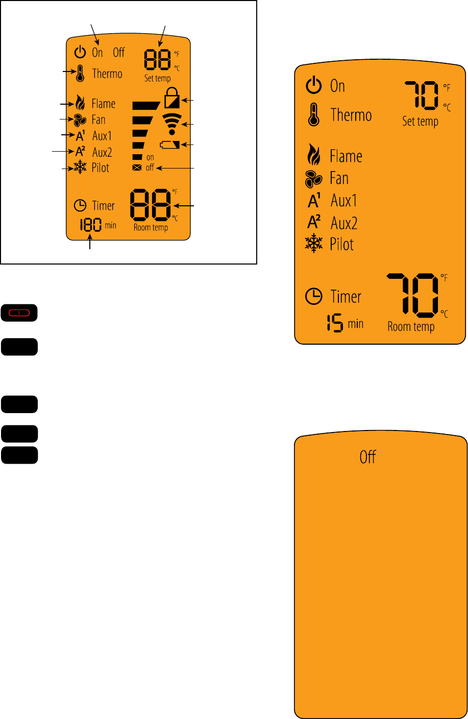
THERMOSTAT STATUS
THERMOSTAT
THERMOSTAT DESIRED
TEMP SETTING
FLAME HEIGHT
FAN SPEED
ADJUSTABLE
AUXILIARY
ADJUSTABLE
OUTPUT (ON/OFF)
TIMER DISPLAY/FUNCTION
CONSTANT PILOT
ROOM TEMP
DISPLAY
FUNCTION LEVEL
INDICATOR
LOW BATTERY
INDICATOR
TRANSMISSION
INDICATOR
CHILD LOCK
INDICATOR
Function Buttons
Menu
Select V
V
UsePOWERbuttontoturntheunitonandoff.
UseMENUbuttontodisplaythemenufunctions.
Only functions that can be activated will be
displayed. For example: Flame Height will not
be displayed when the remote status is OFF.
Use the SELECT button to select the current
feature.
Use the UP and DOWN arrows to toggle through
the menu functions and value selections in the
submenus.
Idle When Remote is in ON Mode
The remote control will go into an idle mode if no but-
tons are pressed within 5 seconds. Press any button to
resume full functionality. In idle mode only active func-
tions will show on the screen.
Standby mode
The remote control will go into a standby mode if no but-
tons are pressed within 5 minutes. Press the POWER
button to reactivate the remote control to ON mode. Ac-
tive functions will be displayed
Menu
Select V
V
Menu
Select V
V
Menu
Select V
V
Menu
Select V
V
Display Screen
Hearth & Home Technologies • RC300 Multifunction Remote Control • 2166-393 • 6/09 5
About ON Mode
• All functions can be accessed when the remote control
is in the ON mode.
• Only active functions will be displayed when the remote
control is in the ON mode. For example: if the fan is the
onlyfunctionthat’sactive,thefaniconandamewillbe
the only icon shown in the display.
About OFF Mode
Only the following functions can be accessed in the OFF
mode:
• AUX1
• AUX2
• Constant Pilot
Only active functions will be displayed when the remote
control is in the OFF mode.
Turning On the Fireplace
• PressthePOWERbuttontoturnthereplaceON.The
replacewillrstignitethepilot.Oncethepilotameis
established the main burner will be lit.
NOTICE: Whenever the replace is cycled from OFF to
ON, the main burner will light on high for 10 seconds before
returning to the previous user setting.
Adjusting Flame Height
• Press the MENU button to activate the menu.
• Using the UP and DOWN arrows highlight the FLAME
icon and press SELECT.
• Use the UP and DOWN arrows to adjust the FLAME
HEIGHT, then press SELECT. The FLAME HEIGHT
canbeadjustedto5differentsettings.
NOTICE: FLAME HEIGHT will not be adjustable for rst
ten seconds when replace is turned on.
NOTICE: The system will remember the previous FLAME
HEIGHT setting and will automatically adjust after 10
seconds.
Adjusting Fan Speed
• Press the MENU button to activate the menu.
• Using the UP and DOWN arrows highlight the FAN icon
and press SELECT.
• Use the UP and DOWNarrowstoadjusttheFAN SPEED,
then press SELECT. The FAN SPEEDcanbeadjusted
to3differentsettings:HIGH,MEDIUM,LOW.
NOTICE: The fan has a timer built into the control module.
After the replace is turned ON the timer will wait for 7
minutes before turning on the fan. In addition, the fan
will remain on for 12 minutes after the replace has been
turned OFF.
NOTICE: Whenever the fan is turned ON, the FAN will start
up on the high setting for 10 seconds before adjusting to
the previous user setting.
AUX1 Function (Unit dependent Function)
• Press the MENU button to activate the menu.
• Using the UP and DOWN arrows highlight the AUX1 icon
and press SELECT.
• Use the UP and DOWNarrowstoadjusttheAUX1 output,
then press SELECT. The AUX1 function canbeadjusted
to4differentsettings:HI,MED,LOWandOFF.
AUX2 Function (Unit dependent Function)
• Press the MENU button to activate the menu.
• Using the UP and DOWN arrows highlight the AUX2 icon
and press SELECT.
• Use the UP and DOWN arrows to turn the AUX2 ON or
OFF, then press SELECT. The AUX2 function can be
either be turned ON or OFF.
NOTICE: The system will remember the previous AUX1
and AUX2 setting from the menu. However, when the re-
place is turned OFF both AUX1 and AUX2 will be turned
off. AUX and AUX2 can be activated when the ame is off
from the remote’s OFF mode. When the replace is turned
back ON the AUX1 and AUX2 settings will be restored to
the previous ON setting.
Hearth & Home Technologies • RC300 Multifunction Remote Control • 2166-393 • 6/09
6
Adjusting Thermostat
• Press the MENU button to activate the menu.
• Using the UP and DOWN arrows highlight the THERMO
icon and press SELECT.
• Use the UP and DOWN arrows to turn the THERMO ON
or OFF, then press SELECT (the SET TEMP will start
blinking). Using the UP and DOWN arrows select the
desired temperature and press SELECT.
NOTICE: If the THERMO function is on, the SET TEMP
can be adjusted at any time by pressing the UP and DOWN
arrows.
NOTICE: As the ROOM TEMP (RT) approaches SET
TEMP (ST), the remote system will automatically adjust
the ame height. If the RT rises above ST, the replace
will shut down the main burner. After this, the replace will
turn back on after the RT drops below the ST.
NOTICE: The system will remember the previous TEM-
PERATURE setting when THERMOSTAT mode is cycled
ON or OFF.
Adjusting Timer
• Press the MENU button to activate the menu.
• Using the UP and DOWN arrows highlight the TIMER
icon and press SELECT.
• Use the UP and DOWN arrows to turn the TIMER ON
or OFF, then press SELECT. Using the UP and DOWN
arrows select the desired set time and press SELECT.
Timer operates in increments of 15, 30, 45, 60, 90, 120
and 180 minutes.
Activating/Deactivating Constant Pilot
• Press the MENU button to activate the menu.
• Using the UP and DOWN arrows highlight the PILOT
icon and press SELECT.
• Use the UP and DOWN arrows to turn the CONSTANT
PILOT ON or OFF, then press SELECT.
NOTICE: A beep will come from the control module
indicating CONSTANT PILOT has been activated. A
double beep will come from the control module indicating
CONSTANT PILOT has been deactivated.
Setting the Child Lock
• Press and hold the MENU and UP arrow buttons simul-
taneously for 4 seconds to enable or disable the child
lock feature.
NOTICE: No functions will be usable until child lock feature
is disabled.
Power Outage
• IfreplacebatterybackupsystemISinstalledattimeof
poweroutage,replaceoperationwillnotbeinterrupted.
• IfreplacebatterybackupsystemISNOTinstalledat
timeofpoweroutage,replacewillshutoff.Toresume
replaceoperation,installbatterybackup.

Hearth & Home Technologies • RC300 Multifunction Remote Control • 2166-393 • 6/09 7
Please contact your Hearth & Home Technologies
dealerwithanyquestionsorconcerns.
For the location of your nearest
Hearth & Home Technologies dealer,
pleasevisitwww.reside.com.
Frequently Asked Questions/Troubleshooting
Symptom Possible Cause Corrective Action
Remote control will not transmit
Batteries Verify batteries are functional and installed correctly.
Remote control is in
Child Lock mode Disengage Child Lock mode.
Buttons not being
pressedrmly
Press button rmly for one to two seconds to ensure
transmission to module.
Control module will not take
commands from remote control
Control module is not in
“REMOTE”mode EnsuremoduleswitchissettoREMOTE.
Control module and
remote control are not
programmed to each
other
The control module will beep when it successfully re-
ceives a command. If it does not beep, clear module
memory and reprogram wall switch.
Control module is
unplugged. In case of
power outage, backup
batteries are depleted or
missing
IfredLEDlightcomesonwhenpowerbuttonispressed,
verifythatthecontrolmoduleispluggedinthereplace
junctionboxlocatedinthecontrolsarea.Alsoverifythat
the batteries are installed in the battery pack.
Fan does not turn on when
replaceisstarted Built in time delay Thereplacemustrunforsevenminutesinorderforthe
fan to engage.
Fan does not turn off when
replaceturnedoff Built in time delay Thefanwillrunfortwelveminutesafterthereplaceis
turned off.
Fireplace shuts down after
extended periods Built-in timer The replace will automatically shut down after nine
hoursofcontinuousoperationinREMOTEmode.
Fireplace is on but will not shut off
with the remote control
Externalwiredwall
switch
Thereplacecannotbeturnedoffbyremoteifanexter-
nal wired switch is installed and in the ON position. Turn
external wall switch to OFF.
Control module failure
At control module, turn off replace by sliding the ON/
OFF/REMOTE switch to OFF. Warning! Risk of Burns!
Fireplace is hot. Use caution when accessing module.
WARNING! Risk of burns! In the event of a wall switch
malfunction, DO NOT attempt to turn off the replace
manually using the control module. The decorative front
will be hot and severe burns may occur. Call you dealer
for assistance.
Operation is subject to the following two conditions:
(1) this device may not cause interference, and
(2) this device must accept any interference, including interference that
may cause undesired operation of the device
You are cautioned that changes or modifications not expressly approved by
the party responsible for compliance could void your authority to operate the
equipment.