Hearth and Home Technologies RF-5AN REMOTE CONTROL KITS User Manual 100 909 SMART BATT II English Pending Eric pmd
Hearth & Home Technologies REMOTE CONTROL KITS 100 909 SMART BATT II English Pending Eric pmd
UserManual.wiki
>
Hearth and Home Technologies
>
RF 5AN User Manual
USERS MANUAL
Navigation menu
Upload a User Manual
Namespaces
Wiki Guide
HTML
PDF
Info
Views
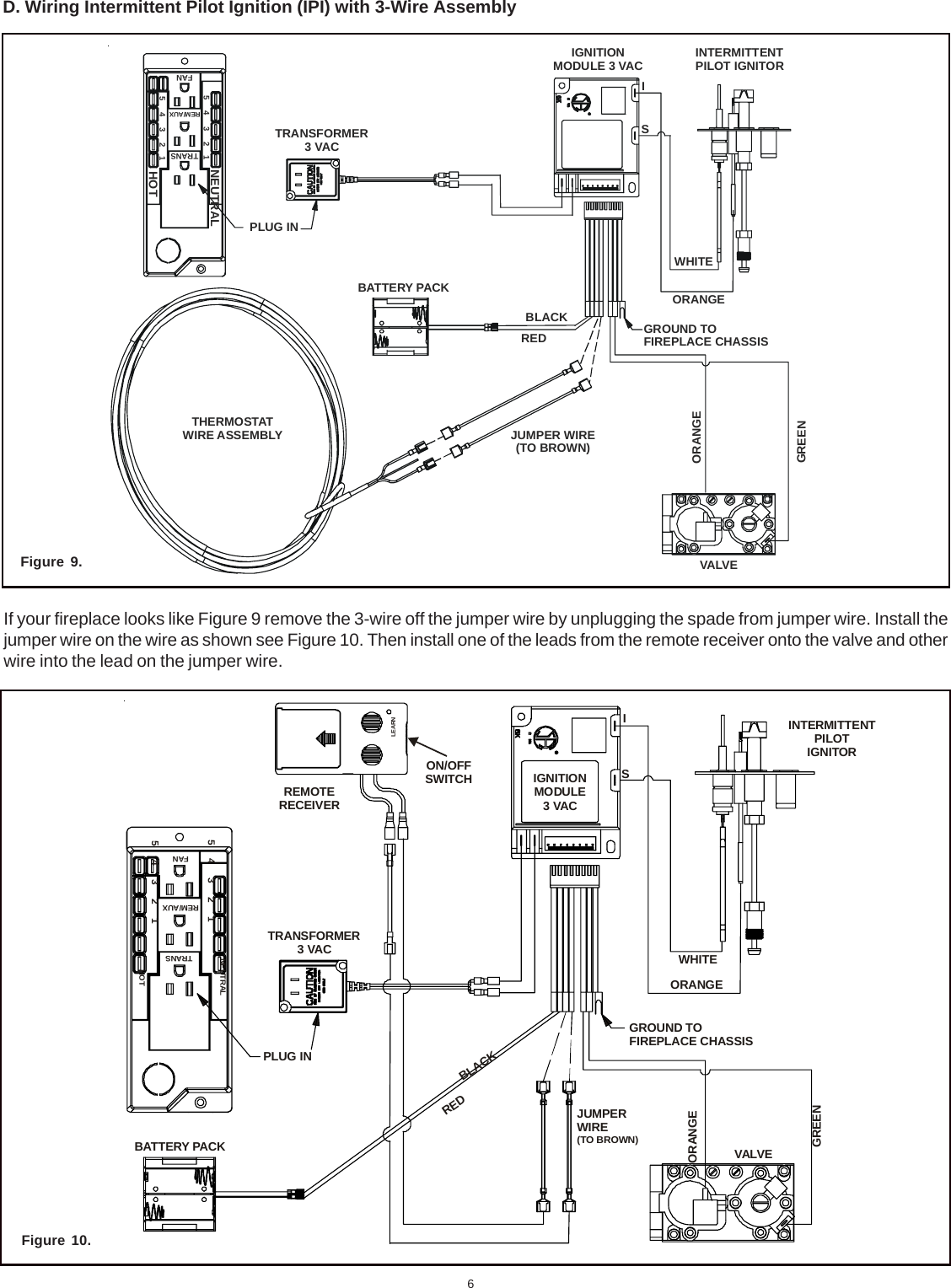
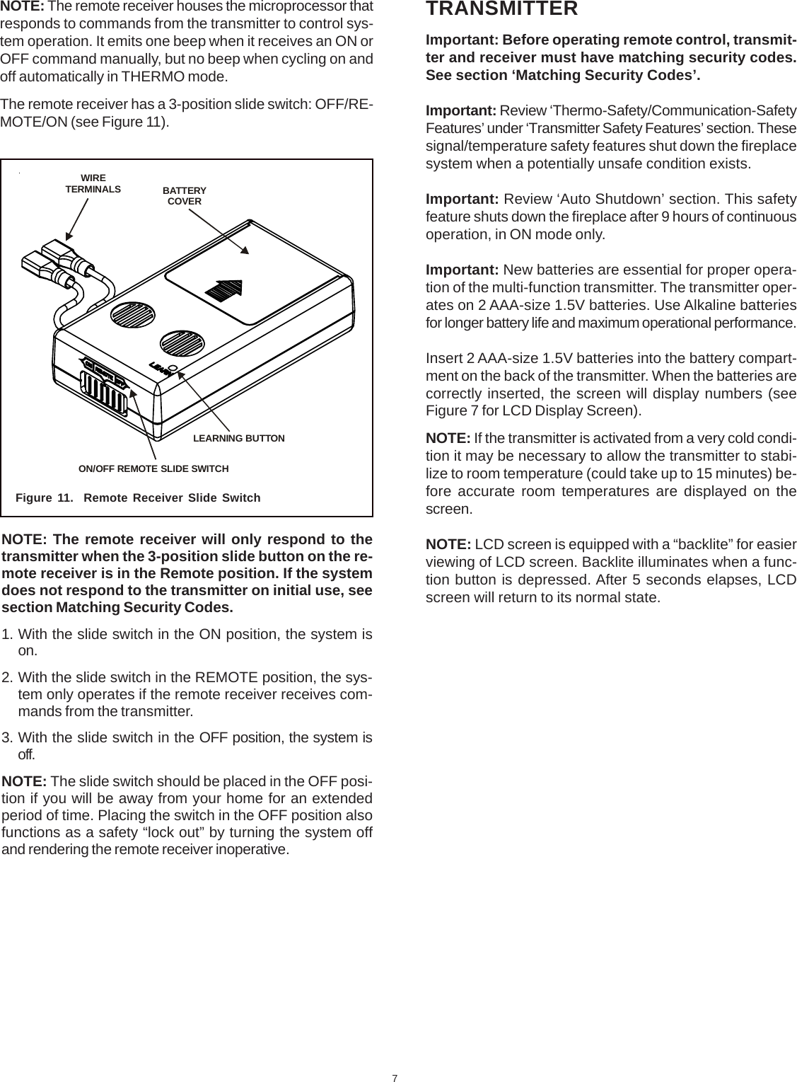
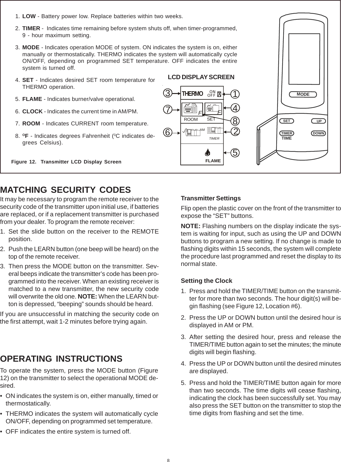
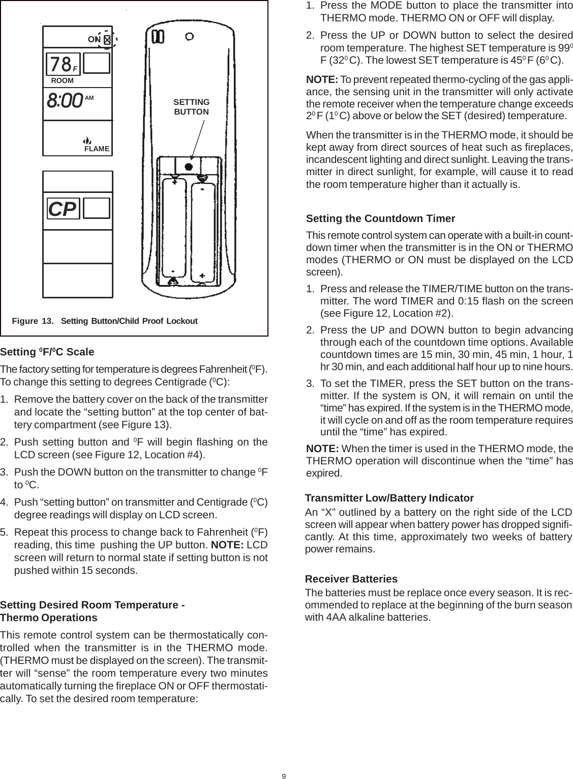
User Manual
Discussion / Help
Navigation