Heat Controller Hdg Quick Start Guide
HDG36 to the manual 19a91e28-d068-4721-875b-ba0cf652761d
2014-07-19
: Heat-Controller Heat-Controller-Hdg-Quick-Start-Guide heat-controller-hdg-quick-start-guide heat-controller pdf
Open the PDF directly: View PDF ![]() .
.
Page Count: 27
Heat Controller, Inc. • 1900 Wellworth Ave. • Jackson, MI 49203 • (517)787-2100 • www.heatcontroller.com
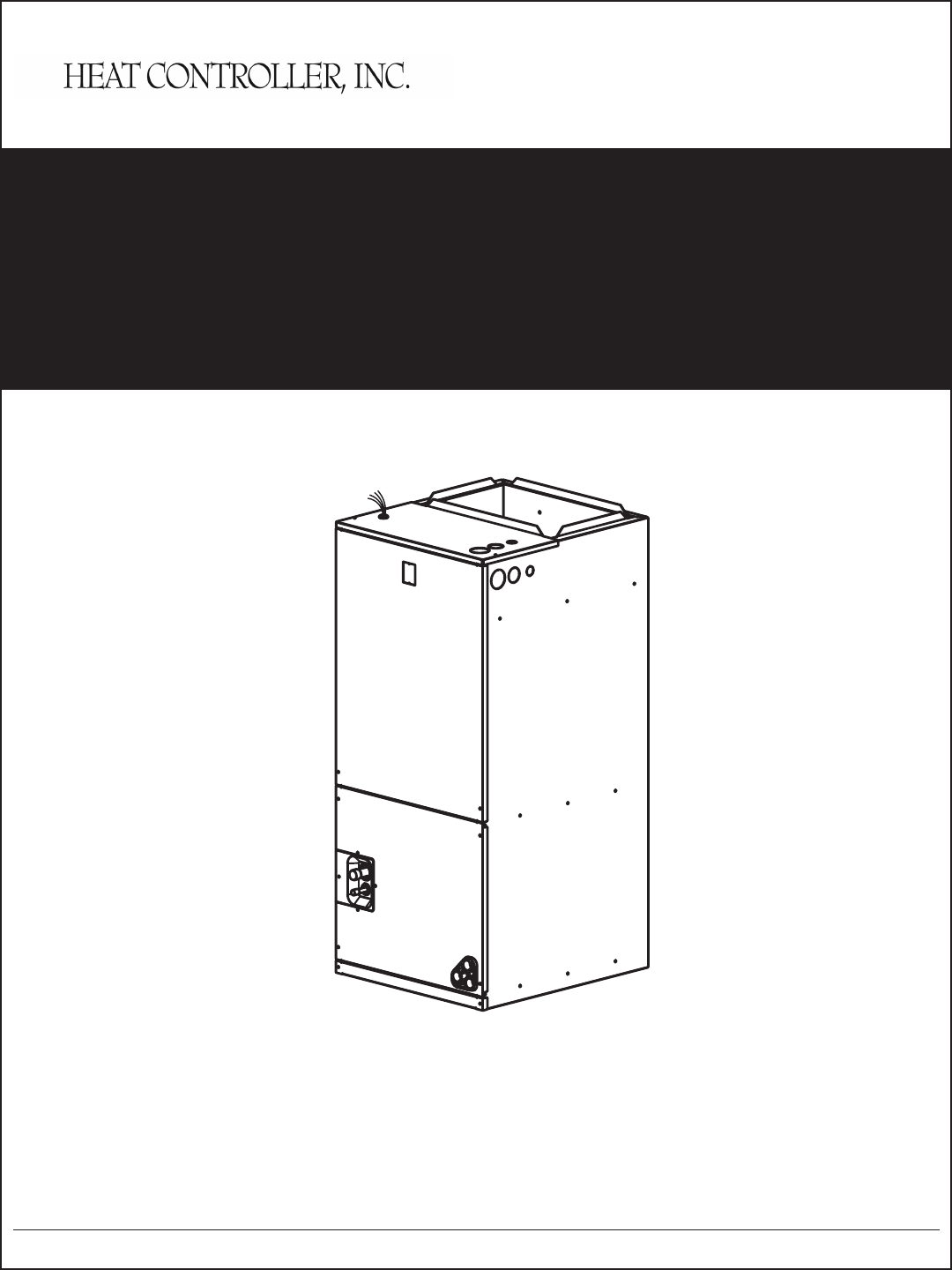
INSTALLATION
INSTRUCTIONS
Air Handler
HDG Series
1.5 to 5 Ton

HDG Series Air Handler INSTALLATION INSTRUCTIONS Heat Controller, Inc.
1
1.0 NOMENCLATURE ...............................................................................................................2
2.0 SAFETY ................................................................................................................................3
3.0 GENERAL ............................................................................................................................6
3.1 UNIT DIMENSIONS ......................................................................................................7
4.0 APPLICATIONS ...................................................................................................................8
4.1 VERTICAL UPFLOW. ...................................................................................................8
4.2 VERTICAL DOWNFLOW..............................................................................................8
4.3 HORIZONTAL ...............................................................................................................9
4.4 INSTALLATION IN AN UNCONDITIONED SPACE .................................................... 11
5.0 ELECTRICAL WIRING ....................................................................................................... 11
5.1 POWER WIRING ........................................................................................................ 11
5.2 CONTROL WIRING ....................................................................................................12
5.3 GROUNDING .............................................................................................................12
5.4 ELECTRICAL DATA ....................................................................................................13
6.0 AIRFLOW PERFORMANCE ..............................................................................................14
7.0 DUCTWORK ......................................................................................................................17
8.0 REFRIGERANT CONNECTIONS ......................................................................................18
8.1 CONDENSATE DRAIN TUBING ................................................................................18
8.2 FLOW RATER PISTON CHANGE ..............................................................................19
9.0 AIR FILTER (not factory-installed) ..................................................................................21
10.0 FILTER INSTALLATION DIMENSIONS ..........................................................................22
10.0 WIRE DIAGRAMS ............................................................................................................23
Table of Contents
Heat Controller, Inc. INSTALLATION INSTRUCTIONS HDG Series Air Handler
2
These instructions are intended as an aid to qualied licensed service personnel for proper
installation, adjustment and operation of this unit. Read these instructions thoroughly before
attempting installation or operation. Failure to follow these instruction may result in improper
installation,adjustment, service or maintenance possibly resulting in re, electrical shock,
property damage, personal injury or death.
H D G 18 F B - 1 A
H = DX Air Handler
A = Hydronic Air Handler
F = Front Return
Design Series
R-410A Refrigerant
18 = 18,000 BTUH
24 = 24,000 BTUH
30 = 30,000 BTUH
36 = 36,000 BTUH
42 = 42,000 BTUH
48 = 48,000 BTUH
60 = 60,000 BTUH
F = Flowrater (Piston)
T = TXV
V = TXV w/ ECM Drive
Condenser/Heat Pump Matching Guide:
H = Heat Pump
C = Air Conditioner
B = Both A/C & H/P use
1 = 208/230V 1 Phase 60Hz
2 = 208/230V 3 Phase 60Hz
Warning
1.0 Nomenclature
A = Revision
Code
NOTE: Not all model congurations are available. The nomenclature exists for future product line development. Consult
your local distributor or Heat Controller’s customer service department regarding available options.
HDG Series Air Handler INSTALLATION INSTRUCTIONS Heat Controller, Inc.
3
This document is customer property and is to remain with this unit.
These instructions do not cover all the different variations systems nor does it provide for every pos-
sible contingency to be met in connection with installtion.
All phases of this installation must comply with NATIONAL STATE AND LOCAL CODES. If additional
information is required please contact your local distributor.
2.0 Safety
This is a safety alert symbol. When you see this symbol on labels or in manuals, be alert to the
potential for personal injury.
This is an attention alert symbol. When you see this symbol on labels or in manuals, be alert to the
potential for personal injury.
Disconnect all power to unit before installing or servicing. More than one disconnect switch may be
required to de-energize the equipment. Hazardous voltage can cause server personal injury or death.
If removal of the blower assembly is required, all disconnect switches supplying power to the
equipment must be de-energized and locked (if not in sight of unit ) so the eld power wires can
be safely removed from the blower assembly. Failure to do so can cause electrical shock result-
ing in personal injuring or death.
Because of possible damage to equipment or personal injury, installation, service, and maintenance
should be performed by a trained, qualied service personnel. Consumer service is recommended
only for lter cleaning / replacement. Never operate the unit with the acess panels removed.
These instructions are intended as an aid to qualied, licensed service personnel for proper
installation, adjustment and operation of this unit. Read these instructions thoroughly before
attempting installation or operation. failure to follow these instructions may result in improper in-
stallation, adjustment, service or maintenance possibly resulting in re, electrical shock, property
damage, personal injury or death.
Warning
Warning
Warning
Warning
Heat Controller, Inc. INSTALLATION INSTRUCTIONS HDG Series Air Handler
4
The unit must be permanently grounded. Failure to do so can result in electrical shock causing
personal injury or death.
PROPOSITION 65: This appliance contains berglass insulation. Respirable particles of
berglass are known to State of California to cause cancer.
All manufacturer products meet current federal OSHA Guidelines for safety. California Proposition
65 warnings are required for certain products, which are not covered by the OSHA standards.
California’s Proposition 65 requires warnings for products sold in California that contain or
produce any of over 600 listed chemicals known to the State of California to cause cancer or birth
defects such as berglass insulation, lead in brass, and combustion products from natural gas.
All “new equipment” shipped for sale in California will only have labels stating that the product
contains and /or produces Proposition 65 chemicals. We cannot always know “when, or if”
products will be sold in the California market, thus all products may not be labeled when their
nal destination is unknown.
You may receive inquiries from customers about chemicals found in, or produced by, some
of our heating and air-conditioning equipment, or found in natural gas used with some of our
products. Listed below are those chemicals and substances commonly associated with similar
equipment in our industry and other manufacturers.
Glass Wool (Fiberglass) Insulation
Carbon Monoxide (CO).
Formaldehyde
Benzene
More details are available at the websites for OSHA (Occupational Safety and Health
Administration), at www.osha.gov and the State of California’s OEHHA (Ofce of Environmental
Health Hazard Assessment), at www.oehha.org. Consumer education is important since the
chemicals and substances on the list are found in our daily lives. Most consumers are aware
that products present safety and health risks, when improperly used, handled and maintained.
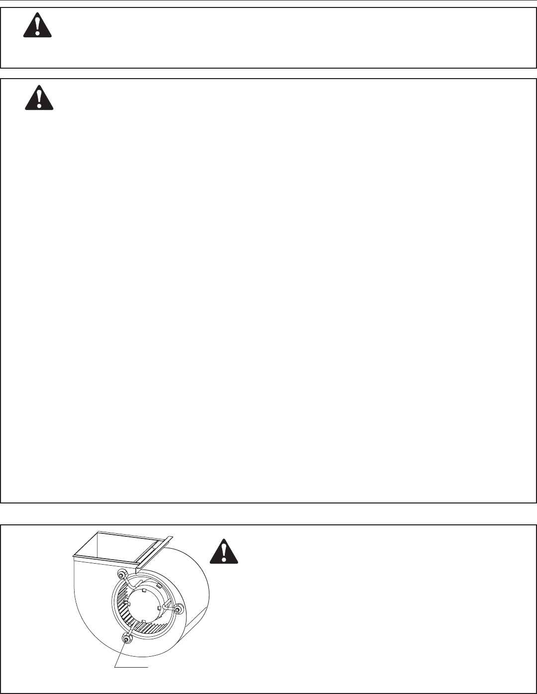
Make sure the blower motor support is tight (3-motor
mount bolts) then check to see if wheel is secured to
motor shaft before operating unit. To avoid electrical
shock, which can result in injury or death, use only the
screws furnished with the motor from the manufacturer.
Warning
Warning
Warning
BLOWER MOTOR BOLT
HDG Series Air Handler INSTALLATION INSTRUCTIONS Heat Controller, Inc.
5
Do not install this unit in manufactured (mobile) homes. Improper installation is more likely in
manufactured housing due to ductwork material, size, location and arrangement. Installations in
manufactured housing can cause re resulting in property damage, personal injury or death.
EXCEPTION: Manufactured housing installations are approved only with documentation by a
recognized inspection authority that veries that the installation has been made in compliance
with the instructions and all warnings have been observed.
Duct leaks can create an unbalanced system and draw pollutants such as direct, dust, fumes
and odors into the home causing property damage. Fumes and odors from toxic, volatile or
ammable chemicals, as well as automobile exhaust and carbon monoxide (CO), can be drawn
into the living space through leaking ducts and unbalanced duct systems causing personal injury
or death (see Figure 1).
• If air-moving equipment or ductwork is located in garages or off-garage storage areas, all joints,
seams, and openings in the equipment and duct must be sealed to limit the migration of toxic
fumes and odors including carbon monoxide from migrating into the living space.
• If air-moving equipment or ductwork is located in spaces containing fuel burning appliances
such as water heaters or boilers, all joints, seams and openings in the equipment and duct
must be sealed to prevent depressurization of the space and possible migration of combustion
byproducts including carbon monoxide into the living space.
When used in cooling applications, excessive sweating may occur when unit is installed in an
unconditioned space. This can result in property damage.
In compliance with recognized codes, it is recommended that an auxiliary drain pan be installed
under all evaporator coils or units containing evaporator coils that are located in any area of a
structure where damage to the building or building contents may occur as a result of an overow
of the coil drain pan or a stoppage in the primary condensate drain piping.
The rst 36 inches of supply air plenum and ductwork must be constructed of sheet metal as
required by NFPA 90B. The supply air plenum or duct must have a solid sheet metal bottom
directly under the unit with no openings, registers or exible air ducts located in it. If exible supply
air ducts are used they may be located only in the vertical walls of rectangular plenum, a minimum
of 6 inches from the solid bottom. Metal plenum of duct may be connected to the combustible oor
base, if not, it must be connected to the unit supply duct exposed to the supply air opening from the
downow unit. Exposing combustible (non-metal) material to the supply opening of a downow unit
can cause a re resulting in property damage, personal injury or death.
Exception warning to downow:
Installations on concrete oor slab with supply air plenum and ductwork completely encased
must be not less than 2 inches of concrete (See NFPA 90A).
Warning
Warning
Notice
Notice
Warning

Heat Controller, Inc. INSTALLATION INSTRUCTIONS HDG Series Air Handler
6
3.0 General
The unit can be positioned for bottom return air in the upow position, left and right return in the horizon-
tal position, top return in downow position.
This Air Handler provides the exibility for installation in any upow or downow horizontal application.
The direct drive motors provides a selection of air volume to match any application. 3-Speed motors
provide selections of air ow to meet desired applications.
Top and side power and control wiring, accessible screw terminals for control wiring all combine to
make the installation easy, and minimize installation cost. Please contact your local distributor.
See Fig. 1 on Pg. 7
HDG Series Air Handler INSTALLATION INSTRUCTIONS Heat Controller, Inc.
7
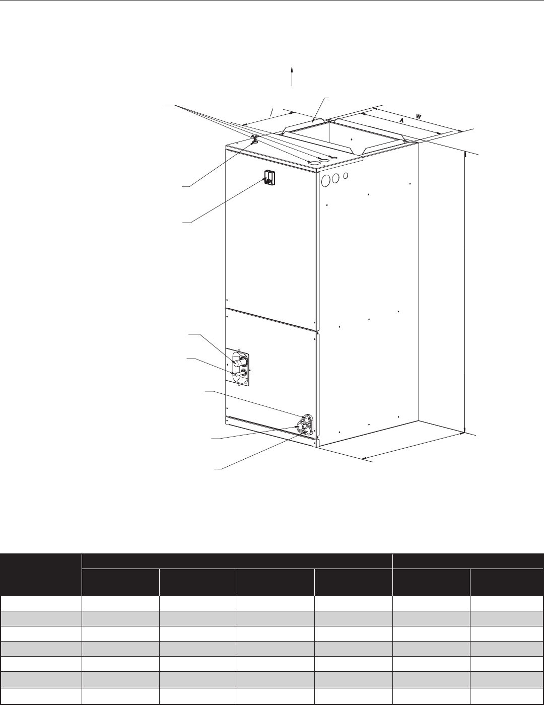
Model Size
Dimensions Unit Weight lbs. [kg]
Unit Height
in. [mm]
Unit Weight
in. [mm]
Unit Lenght
in. [mm]
Supply Duct
“A” in [mm] Net Shipping
HDG18 41 3/8" [1050] 18 1/8" [460] 20 1/2" [520] 16" [406] 106 [48] 119 [54]
HDG 24 41 3/8" [1050] 18 1/8" [460] 20 1/2" [520] 16" [406] 106 [48] 119 [54]
HDG 30 41 3/8" [1050] 18 1/8" [460] 20 1/2" [520] 16" [406] 119 [54] 132 [60]
HDG36 46 1/2" [1180] 19 5/8" [500] 20 5/8" [550] 18" [456] 141 [64] 156 [71]
HDG42 46 1/2" [1180] 19 5/8" [500] 20 5/8" [550] 18" [456] 141 [64] 156 [71]
HDG48 54 1/2” [1385] 22” [560] 24" [610] 19 1/2” [496] 171 [78] 187 [85]
HDG60 54 1/2” [1385] 22” [560] 24" [610] 19 1/2” [496] 171 [78] 187 [85]
UPFLOW UNIT SHOWN;
UNIT MAY BE INSTALLED UPFLOW, DOWNFLOW,
HORIZONTAL RIGHT, OR LEFT AIR SUPPLY.
W
A
10
516
SUPPLY AIR
FLANGES ARE PROVIDED
FOR FIELD INSTALLATION
ELECTRICAL CONNECTIOS
MAY EXIT TOP OR EITHER SIDE
HIGH VOLTAGE CONNECTION 7/8”,
1-23/64”, 1-23/32” DIA KNOCK OUTS
LOW VOLTAGE CONNECTION
BREAKER SWITCH
(FOR ELECTRIC HEATER ONLY)
VAPOR LINE CONNECTION COPPER (SWEAT)
LIQUID LINE CONNECTION COPPER (SWEAT)
AUXILIARY DRAIN CONNCECTION 3/4”
FEMALE PIPE THREAD (NPT)
AUXILIARY DRAIN CONNECTION 3/4”
FEMALE PIPE THREAD (NPT)
PRIMARY DRAIN CONNCETION 3/4”
FEMALE PIPE THREAD (NPT)
H
D
NOTE: 24” CLEARANCE IS REQUIRED IN THE FRONT
OF THE UNIT FOR FILTER AND COIL MAINTENANCE.
HIGH VOLTAGE CONNECTION 7/8”,
1-3/8”, 1-3/4” DIAMETER KNOCK OUTS
Fig. 1 Dimensions
3.1 Unit Dimensions
Dimensional Data
Heat Controller, Inc. INSTALLATION INSTRUCTIONS HDG Series Air Handler
8
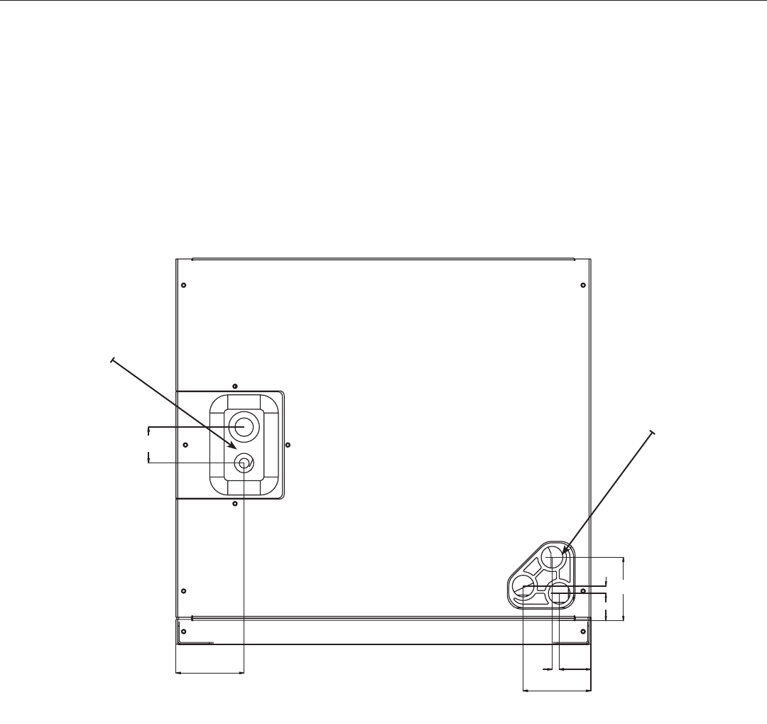
1-9/16
2-15/16 5/16
2-15/16
1-3/8
1-1/4
5/16
2-13/16
Fig.2 Coil Connection Dimensions
4.0 Applications
4.1 Vertical Upow
• Vertical Upow conguration is the factory set on all models (see Fig 1).
• If a side return air opening is required, eld fabricate a return air plenum with an opening large enough
to supply unit and strong enough to support unit weight.
• If return air is to be ducted, install duct ush with oor. Use reproof resilient gasket 1/8 to 1/4 in. thick
between the ducts, unit and oor. Set unit on oor over opening.
IMPORTANT NOTE
Torque applied to drain connections should not exceed 15.ft.lbs.(see Fig.1&2)
Fig. 2 Coil Connection Dimensions
4.2 Vertical Downow
Conversion to Vertical Downow: A vertical upow unit may be converted to vertical downow.
Remove the door and indoor coil and reinstall 180° from original position. See Fig. 2~3.
IMPORTANT: To comply with certication agencies and the National Electric Code for horizontal
right application, the circuit breaker(s) on eld-installed electric heater kits must be re-installed per
procedure below so that the breaker switch “on” position and marking is up and, “off” position and
marking is down.
• To rotate breaker(s): Rotate one breaker set (circuit) at a time starting with the one on the
right. Loosen both lugs on the load side of the breaker. (Make sure that wires are identied
and are reinstalled into proper breaker).Wires are bundles with wire ties, one bundle going to
the right lug and one bundle going to the left lug.
Refrigerant Line
Connections
Drain
Connections
HDG Series Air Handler INSTALLATION INSTRUCTIONS Heat Controller, Inc.
9
• Using a screwdriver or pencil, lift blue plastic tab with hole away from breaker until breaker releas-
es from mounting opening.
• With breaker held in hand, rotate breaker so that “on” position is up, “off” position is down with unit
in planned vertical mounting position. insert right wire bundle into top right breaker lug, ensuring all
strands of all wires are inserted fully into lug, and no wire insulation is in lug.
• Tighten lug as tight as possible while holding circuit breaker. Check wires and make sure each wire
is secure and none are loose. Repeat for left wire bundle in left top circuit breaker lug.
• Replace breaker by inserting breaker mounting tab opposite white pull tab in opening, hook mount-
ing tab over edge in opening.
• With screwdriver or pencil, pull blue tab with hole away from breaker while setting that side of
breaker into opening. When breaker is in place, release tab, locking circuit breaker into location in
opening.
• Repeat above operation for remaining breaker(s) (if more than one is provided).
• Replace single point wiring jumper bar, if it is used, on line side of breaker and tighten securely.
• Double check wires and lugs to make sure all are secure and tight. Check to make sure unit wiring
to circuit breaker load lugs match that shown on the unit wiring diagram.
4.3 HORIZONTAL
Horizontal right is the default factory conguration for the units.
Horizontal left isn’t the default factory conguration for the units.
Conversion to Horizontal: A vertical upow unit may be converted to horizontal right by removing indoor
coil assembly and reinstalling coil as shown for right hand air supply. And reinstall coil in unit as shown
for right hand air supply.
• Reinstall the indoor coil 180° from original position. Ensure the retaining channel is fully engaged
with the coil rail. See Fig. 3.
• Rotate unit into the downow position, with the coil compartment on top and the blower compart-
ment on bottom. See Fig. 3.
• Secondary drain pan kits are required when the unit is congured for the horizontal right position
over a nished ceiling and/or living space.
Caution
When using the unit with electrical heater, the switch is used only for electrical heater
on the front of panel.
Heat Controller, Inc. INSTALLATION INSTRUCTIONS HDG Series Air Handler
10
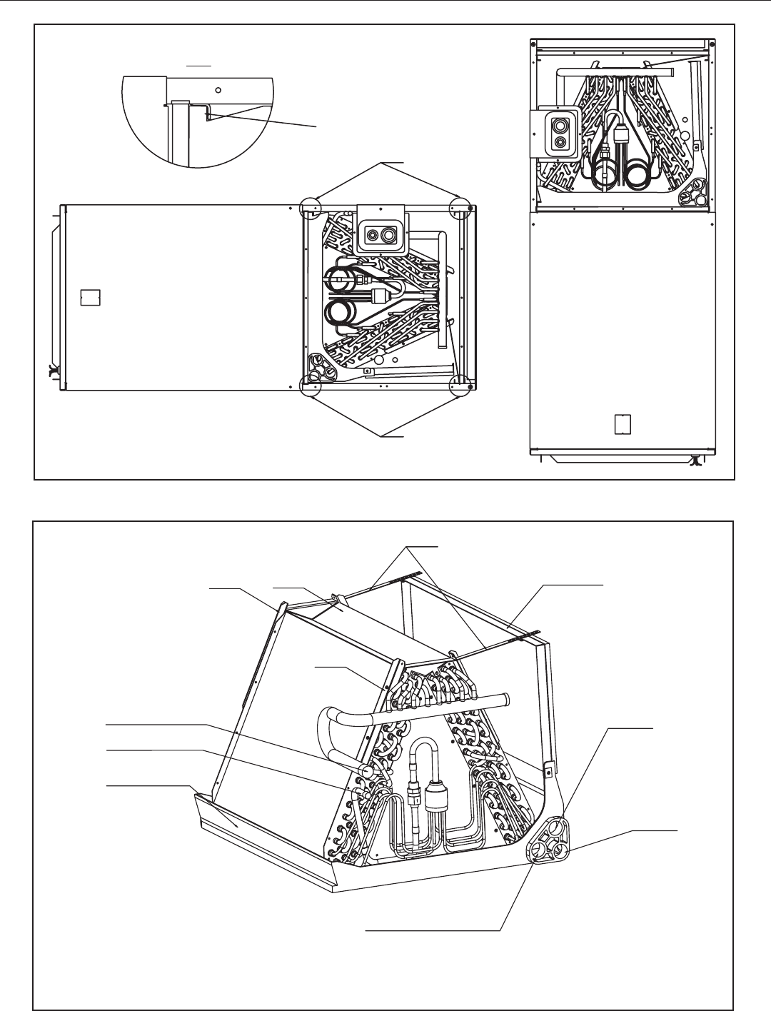
Fig.4 INDOOR COIL AND DRAIN PAN SET-UP
A
1:4
A
RAILS
RAILS
DETAIL A
ENSURE THE RETAINING
CHANNEL IS FULLY ENGAGED
WITH THE COIL RAIL.
HORIZONTAL ADAPTER KIT
VAPOR LINE CONNECTION
LIQUID LINE CONNECTION
PRIMARY DRAIN
CONNECTION
VERTICAL DRAIN PAN
AUXILIARY HORIZONTAL
AUXILIARY UPFLOW/DOWNFLOW
STRAPS
REAR WATER CATCHER
FRONT WATER
CATCHER
TOP AIR STOP
DRAIN CONNECTION
DRAIN CONNECTION
Fig.3 VERTICAL DOWNFLOW & HORIZONTAL LEFT APPLICATIONS
(lower front service panel removed “view”.)
The Max. resistant pressure of evaporator is up to 16MPa (2320PSI)
HDG Series Air Handler INSTALLATION INSTRUCTIONS Heat Controller, Inc.
11
Horizontal units must be congured for right hand air supply or left hand air supply. Horizontal
drain pan must be located under indoor coil. Failure to use the drain pan can result in property
damage.
Conversion in Horizontal Direction: Horizontal left-hand supply can be changed to horizontal
right-hand supply by removing the indoor coil and reinstalling 180° from original.
4.4 INSTALLATION IN AN UNCONDITIONED SPACE
IMPORTANT: There are two pairs of coil rails in the air handler for default and counter ow
application. If the air handler is installed in an unconditioned space, the two unused coil rails
should be removed to minimize air handler surface sweating. The coil rails can be easily re-
moved by taking off the 6 mounting screws from both sides of the cabinet.
5.0 ELECTRICAL WIRING
Field wiring must comply with the National Electric Code (C.E.C. in Canada) and any applicable
local ordinance.
Disconnect all power to unit before installing or servicing. More than one disconnect switch may
be required to de-energize the equipment. Hazardous voltage can cause severe personal injury
or death.
5.1 POWER WIRING
It is important that proper electrical power is available for connection to the unit model
being installed. See the unit nameplate, wiring diagram and electrical data in the installation
instructions.
• If required, install a branch circuit disconnect of adequate size, located within sight of,
and readily accessible to the unit.
• IMPORTANT: After the Electric Heater is installed, units may be equipped with one, two,
or three 30/60 amp. circuit breakers. These breaker(s) protect the internal wiring in the
event of a short circuit and serve as a disconnect. Circuit breakers installed within the
unit do not provide over-current protection of the supply wiring and therefore may be
sized larger than the branch circuit protection.
• Supply circuit power wiring must be 167°F [75°C] minimum copper conductors only. See
Electrical Data In this section for ampacity, wire size and circuit protector requirement.
Supply circuit protective devices may be either fuses or “HACR” type circuit breakers.
• Power wiring may be connected to either the right, left side or top. Three 7/8”, 1-3/8”,
1-3/4” diameter concentric knockouts are provided for connection of power wiring to unit.
• Power wiring is connected to the power terminal block in unit electric cabinet.
Caution
Heat Controller, Inc. INSTALLATION INSTRUCTIONS HDG Series Air Handler
12
5.2 CONTROL WIRING
IMPORTANT: Class 2 low voltage control wiring should not be run in conduit with main power
wiring and must be separated from power wiring, unless class 1 wire of proper voltage rating is
used.
• Low voltage control wiring should be 18 Awg. color-coded. For lengths longer than 100 ft.,
16 Awg. wire should be used.
• Low voltage control connections are made to low voltage pigtails extending from top of air
handler (upow position - see Figure 3). Connections for control wiring are made with wire
nuts. Control wiring knockouts (518 and 7/8) are also provided on the right and left side of
the unit for side connection.
• See wiring diagrams attached to indoor and outdoor sections to be connected.
• Make sure, after installation, separation of control wiring and power wiring has been
maintained.
5.3 GROUNDING
The unit must be permanently grounded. FaIlure to do so can result In electrical shock
causing personal injury or death.
• This product must be sufciently ground in accordance with National Electric Code (C.E.C.
in Canada) and any applicable local ordinace.
• Grounding may be accomplished by grounding metal conduit when installed in accord
ance with electrical codes to the unit cabinet.
• Grounding may also be accomplished by attaching ground wire(s) to ground lug(s)
provided in the unit wiring compartment.
• Ground lug(s) are located close to wire entrance on left side of unit (up-ow). Lug(s) may
be moved to marked locations near wire entrance on right side of unit (upow). If alternate
location is more convenient.
• Use of multiple supply circuits require grounding of each circuit to lug(s) provided in unit.
Caution
HDG Series Air Handler INSTALLATION INSTRUCTIONS Heat Controller, Inc.
13
Model Voltage HP RPM SPEEDS
CIRCUIT
AMPS.
MINIMUM
CIRCUIT
AMPACITY
MAXIMUM
CIRCUIT
PROTECTOR
HDG18 208/230-1-60 1/8 580 3 0.68 1 15(A)
HDG24 208/230-1-60 1/5 701 3 0.95 1.5 15(A)
HDG30 208/230-1-60 1/4 872 3 1.48 2 15(A)
HDG36 208/230-1-60 1/2 794 3 1.63 3 15(A)
HDG42 208/230-1-60 1/2 882 3 1.80 3 15(A)
HDG48 208/230-1-60 1/2 845 3 2.11 3 15(A)
HDG60 208/230-1-60 3/4 963 3 2.79 3 15(A)
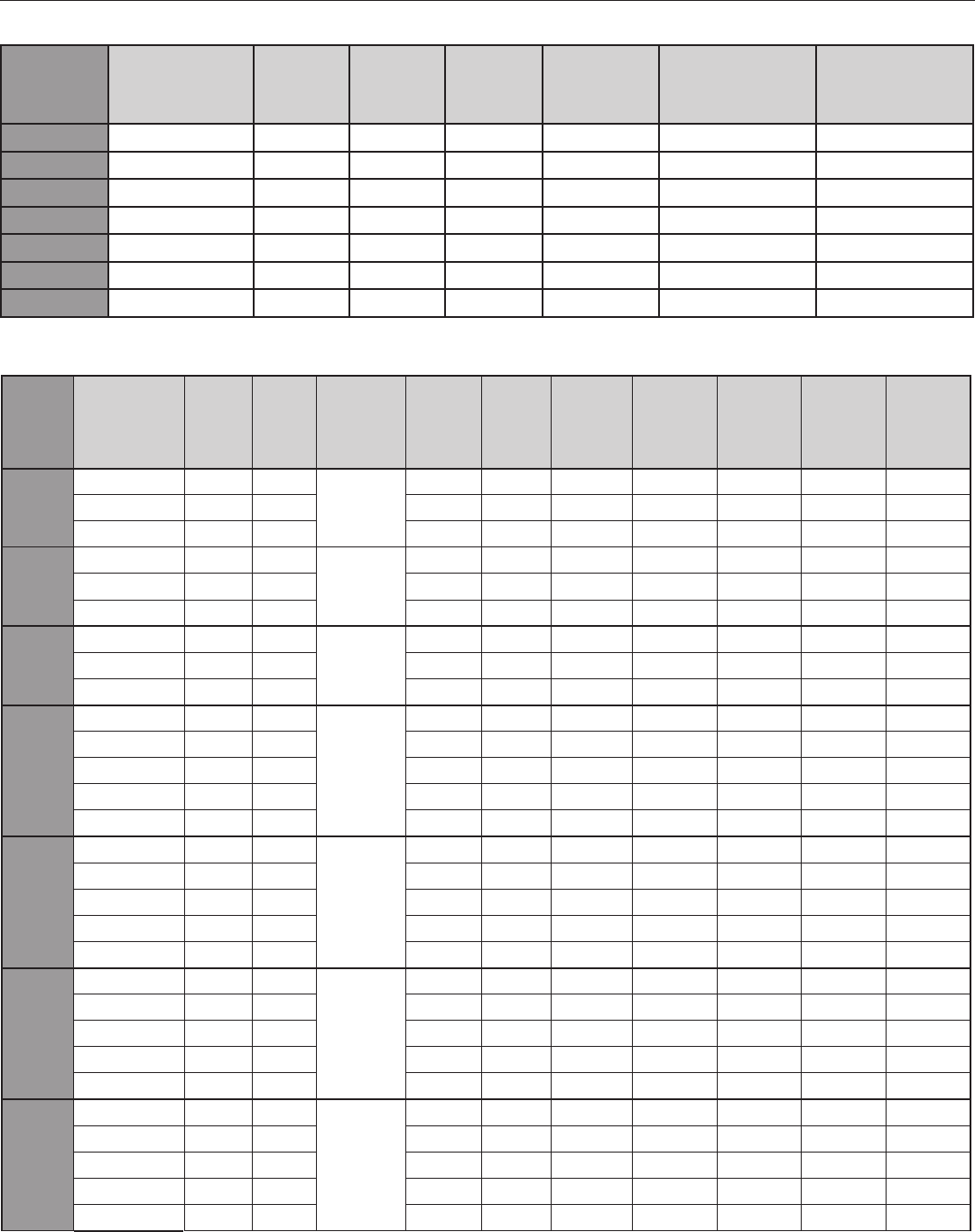
5.4 Electrical Data– BLOWER ONLY, NO ELECTRIC HEAT
Air
Handler
Model
Heater
Model No.
Heater
kW
(208V)
Heater
kW
(240V) PH/Hz
Circuit
Amps
(208V)
Circuit
Amps
(240V)
Motor
Ampacity
Minimum
Circuit
Ampacity
(208V)
Minimum
Circuit
Ampacity
(240V)
Maximum
Circuit
Protection
(208V)
Maximum
Circuit
Protection
(240V)
HDG18
7800-505-1D 3.8 5
1Ph/60Hz
18.1 20.8 0.68 23.5 26.9 25 30
7800-508-1D 5.6 7.5 27.1 31.3 0.68 34.8 40 35 45
7800-510-1D 7.5 10 36.1 41.7 0.68 46 53 50 60
HDG24
7800-505-1D 3.8 5
1Ph/60Hz
18.1 20.8 0.95 23.8 27.3 25 30
7800-508-1D 5.6 7.5 27.1 31.3 0.95 35.1 40.3 40 45
7800-510-1D 7.5 10 36.1 41.7 0.95 46.4 53.3 50 60
HDG30
7800-505-1D 3.8 5
1Ph/60Hz
18.1 20.8 1.48 24.5 27.9 25 30
7800-508-1D 5.6 7.5 27.1 31.3 1.48 35.8 41 40 45
7800-510-1D 7.5 10 36.1 41.7 1.48 47 54 50 60
HDG36
7800-505-1D 3.8 5
1Ph/60Hz
18.1 20.8 1.63 24.7 28.1 25 30
7800-508-1D 5.6 7.5 27.1 31.3 1.63 35.9 41.1 40 45
7800-510-1D 7.5 10 36.1 41.7 1.63 47.2 54.2 50 55
7800-515-1D 11 15 54.2 62.5 1.63 69.8 80.2 70 90
7800-520-1D 15 20 72.2 83.3 1.63 92.4 106.3 100 125
HDG42
7800-505-1D 3.8 5
1Ph/60Hz
18.1 20.8 1.80 24.9 28.3 25 30
7800-508-1D 5.6 7.5 27.1 31.3 1.80 36.2 41.4 40 45
7800-510-1D 7.5 10 36.1 41.7 1.80 47.4 54.4 50 60
7800-515-1D 11 15 54.2 62.5 1.80 70 80.4 80 90
7800-520-1D 15 20 72.2 83.3 1.80 92.6 106.5 100 125
HDG48
7800-505-1D 3.8 5
1Ph/60Hz
18.1 20.8 2.11 25.3 28.7 30 30
7800-508-1D 5.6 7.5 27.1 31.3 2.11 36.5 41.7 40 45
7800-510-1D 7.5 10 36.1 41.7 2.11 47.8 54.8 50 60
7800-515-1D 11 15 54.2 62.5 2.11 70.4 80.8 80 90
7800-520-1D 15 20 72.2 83.3 2.11 93 106.9 100 125
HDG60
7800-505-1D 3.8 5
1Ph/60Hz
18.1 20.8 2.79 26.1 29.6 30 30
7800-508-1D 5.6 7.5 27.1 31.3 2.79 37.4 42.6 40 45
7800-510-1D 7.5 10 36.1 41.7 2.79 48.7 55.6 50 60
7800-515-1D 11 15 54.2 62.5 2.79 71.2 81.7 80 90
7800-520-1D 15 20 72.2 83.3 2.79 93.8 107.7 100 125
5.5 Electrical Data– ELECTRIC HEAT
Heat Controller, Inc. INSTALLATION INSTRUCTIONS HDG Series Air Handler
14
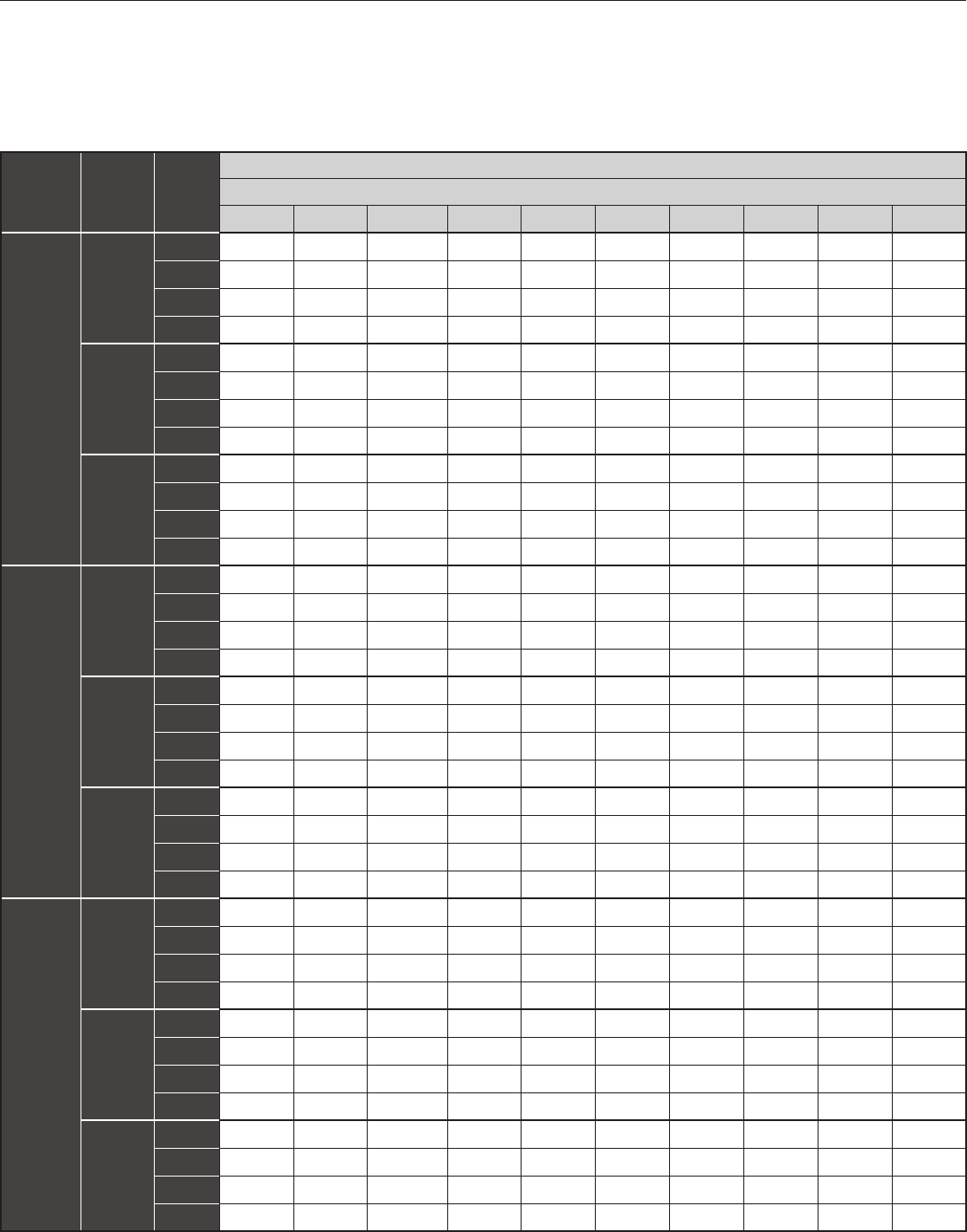
6.0 Airow Performance
Airow performance data is based on cooling performance with a coil and no lter in place. Select perfor-
mance table for appropriate unit size. Make sure external static applied to unit allows operation within the
minimum and maximum limits shown in table below for both cooling and electric heat operation.
Airow Performance Data
continued on next page
Model
Number
Motor
Speed
CFM (Watts)
External Static Pressure-Inches W.C. [kPa]
0 [0] 0.1 [.02] 0.16 [.04] 0.2 [.05] 0.3 [.07] 0.4 [.10] 0.5 [.12] 0.6 [.15] 0.7 [.17] 0.8 [.20]
HDG18
Low
CFM 551 509 - 462 393 345 280 ---
RPM 440 518 - 595 679 726 781 ----
Watts 122.4 120 - 116.8 116.3 109.9 106.2 ---
Amps 0.62 0.62 - 0.62 0.61 0.61 0.60 ---
Middle
CFM 661 622 - 577 506 443 400 ---
RPM 518 580 - 640 731 770 812 ---
Watts 145.2 143 - 140.8 136.3 133.6 131.2 ---
Amps 0.69 0.68 - 0.68 0.67 0.67 0.66 ---
High
CFM -- -- -- 590 550 487 400
RPM -- -- -- 894 911 940 975
Watts -- -- -- 232 229.5 224.4 217.4
Amps -- -- -- 1.16 1.15 1.14 1.12
HDG24
Low
CFM 646 623 - 592 553 506 453 ---
RPM 528 591 - 650 728 790 840 ---
Watts 169.4 166.4 - 163 157.5 151.3 146.3 ---
Amps 0.79 0.78 - 0.78 0.77 0.76 0.75 ---
Middle
CFM 815 802 - 771 733 681 613 ---
RPM 658 701 - 743 790 841 888 ---
Watts 218 216.6 - 214.4 211.4 207.4 203 ---
Amps 0.96 0.95 - 0.95 0.94 0.93 0.92 ---
High
CFM -- -- -- 780 695 607 515
RPM -- -- -- 919 956 986 1014
Watts -- -- -- 262.6 256.4 250.1 243
Amps -- -- -- 1.21 .181 .171 .15
HDG30
Low
CFM 962 913 886 870 813 750 690 - - -
RPM 729 754 798 809 858 873 902 - - -
Watts 315 304 298 292 280 269 258 - - -
Amps 1.39 1.35 1.32 1.30 1.26 1.22 1.19 - - -
Middle
CFM 1094 1043 1012 988 927 861 788 - - -
RPM 809 845 859 885 911 932 954 - - -
Watts 334 325 319 315 303 290 279 - - -
Amps 1.46 1.43 1.40 1.38 1.35 1.30 1.26 - - -
High
CFM 1374 1311 1268 1240 1164 1084 996 910 828 744
RPM 910 937 947 954 972 989 1004 1018 1033 1043
Watts 440 427 419 413 398 381 366 352 340 331
Amps 1.94 1.90 1.86 1.84 1.79 1.74 1.68 1.63 1.60 1.56
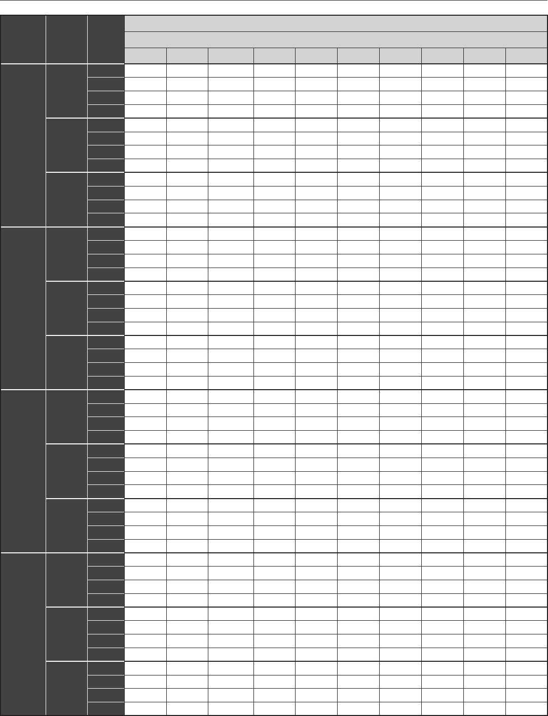
HDG Series Air Handler INSTALLATION INSTRUCTIONS Heat Controller, Inc.
15
Model
Number
Motor
Speed
CFM (Watts)
External Static Pressure-Inches W.C. [kPa]
0 [0] 0.1 [.02] 0.16 [.04] 0.2 [.05] 0.3 [.07] 0.4 [.10] 0.5 [.12] 0.6 [.15] 0.7 [.17] 0.8 [.20]
HDG36
Low
CFM 1129 1088 1061 1040 988 941 819 - - -
RPM 642 675 706 732 771 817 853 - - -
Watts 322 312 306 301 289 269 254 - - -
Amps 1.54 1.52 1.51 1.50 1.47 1.42 1.39 - - -
Middle
CFM 1317 1268 1237 1217 1157 1111 1027 - - -
RPM 776 810 841 874 905 935 966 - - -
Watts 360 354 348 345 335 323 309 - - -
Amps 1.69 1.67 1.66 1.65 1.63 1.60 1.57 - - -
High
CFM 1643 1581 1544 1518 1446 1356 1261 1123 915 812
RPM 868 883 895 906 931 955 978 1013 1028 1050
Watts 463 451 443 438 429 415 401 371 356 343
Amps 2.22 2.20 2.18 2.17 2.14 2.12 2.09 2.03 1.99 1.96
HDG42
Low
CFM 1239 1203 1178 1161 1117 1070 1000 - - -
RPM 738 775 797 808 844 872 905 - - -
Watts 396 385 376 371 360 345 327 - - -
Amps 1.73 1.68 1.64 1.62 1.57 1.52 1.44 - - -
Middle
CFM 1480 1431 1399 1379 1319 1259 1187 - - -
RPM 843 865 882 893 915 937 959 - - -
Watts 430 416 407 401 388 375 359 - - -
Amps 1.87 1.81 1.77 1.75 1.69 1.63 1.57 - - -
High
CFM 1738 1682 1639 1618 1548 1477 1378 1286 1042 908
RPM 921 941 949 955 970 985 1002 1016 1042 1059
Watts 508 493 486 478 460 445 431 412 373 354
Amps 2.22 2.15 2.12 2.08 2.01 1.94 1.89 1.81 1.65 1.58
HDG48
Low
CFM 1471 1427 1395 1374 1316 1247 1180 -- -
RPM 694 732 753 769 803 833 864 -- -
Watts 381 376 372 370 364 357 349 -- -
Amps 1.66 1.64 1.63 1.62 1.61 .581 .550 --
Middle
CFM 1729 1678 1646 1625 1558 1491 1402 -- -
RPM 790 817 833 845 876 898 920 -- -
Watts 485 477 473 470 460 451 240 -- -
Amps 2.14 2.12 2.09 2.08 2.06 2.03 1.99 -- -
High
CFM 2045 1992 1951 1928 1847 1763 1677 1563 1450 1317
RPM 895 920 932 938 956 972 987 1002 1015 1030
Watts 641 627 617 612 596 582 566 546 528 507
Amps 2.86 2.82 2.82 .782 .732 .682 .642 .572 .522 .450
HDG60
Low
CFM 1786 1740 1709 1688 1630 1562 1489 -- -
RPM 830 843 849 856 890 921 942 -- -
Watts 584 569 560 552 536 516 497 -- -
Amps 2.64 2.59 2.55 2.54 2.58 2.42 2.37 -- -
Middle
CFM 2140 2071 2039 2006 1932 1799 1677 -- -
RPM 917 930 938 943 957 970 990 -- -
Watts 645 630 623 617 602 585 569 -- -
Amps 2.87 2.81 2.78 2.76 2.71 2.65 2.59 -- -
High
CFM 2357 2276 2225 2188 2100 2004 1902 1764 1554 1393
RPM 964 976 982 990 1001 1012 1022 1032 1042 1063
Watts 754 733 718 710 693 673 650 630 607 575
Amps 3.34 3.27 3.22 3.19 3.12 3.05 2.98 2.91 2.83 2.71
Heat Controller, Inc. INSTALLATION INSTRUCTIONS HDG Series Air Handler
16
Terminal
Fan speed
Medium
High
Low
Fan M1 M2
Red Blue B lack
Black Blue Red
Blue Red Black
Fan speed switch congurations:
1. All motors are shipped from the factory at medium speed as default.
2. To charge the fan speed to high speed:
• Connect the black wire to the fan terminal
• Connect the blue wire to the M1 terminal
• Connect the red wire to the M2 terminal
3. To charge the fan spped to low speed
• Connect the blue wire to the fan terminal
• Connect the red wire to the M1 terminal
• Connect the black wire to the M2 terminal
The air distribution system has the greatest effect on airow. The duct system is totally controlled by the
contractor. For this reason, the contractor should use only industry-recognized procedures.
Heat pump systems require a specied airow. Each ton of cooling requires between 350 and 450 cubic
feet of air per minute (CFM), or 400 CFM nominally.
Duct design and construction should be carefully done. System performance can be lowered dramati-
cally through bad planning or workmanship.
Air supply diffusers must be selected and located carefully. They must be sized and positoined to deliver
treated air along the perimerter of the space. If they are too small for their intended airow, they become
noisy. If they are not located properly, they cause drafts. Return air grilles must be properly sized to carry
air back to the blower.If they are too small, they also cause noise.
The installers should balance the air distribution system to ensure proper quiet airow to all rooms in the
home. This ensures a comfortable living space.
An air velocity meter or airow hood can give a reading of system CFM.
HDG Series Air Handler INSTALLATION INSTRUCTIONS Heat Controller, Inc.
17
7.0 DUCTWORK
Field ductwork must comply with the National Fire Protection Association NFPA 90A, NFPA 90B and any
applicable local ordinance.
Do not, under any circumstances, connect return ductwork to any other heat producing device such
as replace insert, stove, etc. Unauthorized use of such devices may result in re, carbon monoxide
poisoning, explosion, personal injury or property damage.
Sheet metal ductwork run in unconditioned spaces must be insulated and covered with a vapor barrier. Fi-
brous ductwork may be used if constructed and installed in accordance with SMACNA Construction Stan-
dard on Fibrous Glass Ducts. Ductwork must comply with National Fire Protection Association as tested by
U/L Standard 181 for Class I Air Ducts. Check local codes for requirements on ductwork and insulation.
• Duct system must be designed within the range of external static pressure the unit is designed
to operate against. It is important that the system airow be adequate. Make sure supply and
return ductwork, grills, special lters, accessories, etc. are accounted for in total resistance.
See airow performance tables in this manual.
• Design the duct system in accordance with “ACCA” Manual “D” Design for Residential Winter
and Summer Air Conditioning and Equipment Selection. Latest editions are available from:
“ACCA” Air Conditioning Contractors of America, 1513 16th Street, N.W., Washington, D.C.
20036. If duct system incorporates exible air duct, be sure pressure drop Information (straight
length plus all turns) shown in “ACCA” Manual “D” is accounted for in system.
• Supply plenum is attached to the 3/4” duct anges supplied with the unit. Attach anges
around the blower outlet.
IMPORTANT: If an elbow is included in the plenum close to the unit, it must not be smaller than the
dimensions of the supply duct ange on the unit.
• IMPORTANT: The front ange on the return duct if connected to the blower casing must not
be screwed into the area where the power wiring is located. Drills or sharp screw points can
damage insulation on wires located inside unit.
• Secure the supply and return ductwork to the unit anges, using proper fasteners for the type
of duct used and tape the duct-to-unit joint as required to prevent air leaks.
Warning
Heat Controller, Inc. INSTALLATION INSTRUCTIONS HDG Series Air Handler
18
8.0 REFRIGERANT CONNECTIONS
Keep the coil connections sealed until refrigerant connections are made. See the Installation Instructions
for the outdoor unit for details on line sizing, tubing installation, and charging information.
Coil is shipped with “No charge”. Evacuate the system before charging with refrigerant.
Install refrigerant tubing so that it does not block service access to the front of the unit.
Nitrogen should ow through the refrigerant lines while brazing.
Use a brazing shield to protect the cabinet’s paint and a wet rag to protect the rubber grommet from be-
ing damaged by torch ames. After the refrigerant connections are made, seal the gap around the con-
nections with pressure sensitive gasket.
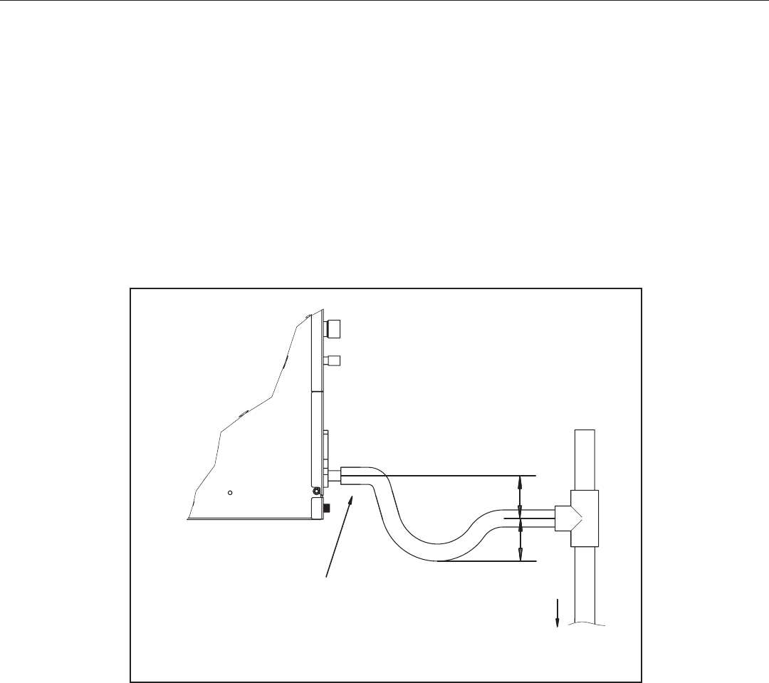
8.1 CONDENSATE DRAIN TUBING
Consult local codes for specic requirements.
IMPORTANT:
1. When making drain tting connections to the drain pan, use a thin layer of Teon paste, silicone
or Teon tape and install, hand tighten.
2. When making drain tting connections to drain pan, do not overtighten. Over tightening ttings
can split pipe connetions on the drain pan.
• Install drain lines so they do not block service access to front of the unit. Minimum clearance of 24
inches is required for lter, coil or blower removal and service access.
• Make sure unit is level or pitched slightly toward primary drain connection so that water will drain
completely from the pan. (See Fig. 5)
• Do not reduce drain line size less than connection size provided on condensate drain pan.
• All drain lines must be pitched downward away from the unit a minimum of 1/8” per foot of line to
ensure proper drainage.
• Do not connect condensate drain line to a closed or open sewer pipe. Run condensate to an open
drain or run line to a safe outdoor area.
CONDENSATE DRAIN TRAP
DO NOT OVERTIGHTEN DRAIN FITTING
TOWARD DRAIN CONNECTION
UNIT MUST BE SLIGHTLY INCLINED
Fig. 5 CONDENSATE DRAIN TRAP
3"
3"
UNIT
TO APPROVED DRAIN
DO NOT OPERATE UNIT WITHOUT
CONDENSATE DRAIN TRAP.
HDG Series Air Handler INSTALLATION INSTRUCTIONS Heat Controller, Inc.
19
• The drain line should be insulated where necessary to prevent sweating and damage due to conden-
sate forming on the outside surface of the line.
• Make provisions for disconnecting and cleaning of the primary drain line should it become neces-
sary. Install a 3 inch trap in the primary drain line as close to the unit as possible. Make sure that the
top of the trap is below connection to the drain pan to allow complete drainage of pan (See Fig. 5).
• Auxiliary drain line should be run to a place where it will be noticeable if it becomes operational.
Homeowner should be warned that a problem exists if water should begin running from the auxiliary
drain line.
• Plug the unused drain connection with the plugs provided in the parts bag, using a thin layer of tef-
lon paste, silicone or teon tape to form a water tight seal.
• Test condensate drain pan and drain line after installation is complete. Pour water into drain pan,
enough to ll drain trap and line. Check to make sure drain pan is draining completely, no leaks are
found in drain line ttings, and water is draining from the termination of the primary drain line.
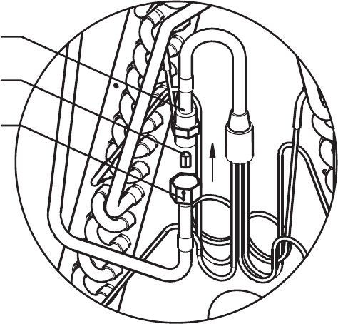
In most applications, there is no need to change the piston (orice). However, in some applications,
changing the piston size is required. If the application requires a different piston/owrator, change the
piston in the distributor of indoor coil before installing the coil. See Table 1 for orice size.
To change the piston, use following steps:
1. Remove cover panel.
2. Use Two wrenches.
Loosen one turn to release pressure. (High pressure gas)
3. After releasing pressure.
Loosen and carefully pull a part the two ttings to expose piston.
4. Remove factory installed piston and replace with recommended piston from Table 1 as shown in Fig.7.
5. Carefully reassemble assembly. (Hand tighten)
Be sure to use teon tape on thread for a complete seal.
6. Hand tighten and make sure assembly is properly connected and then torque to 10-30 ft/lb.
NOTE: Be careful not to bend tubing
8.2 Flowrator Piston Change
NUT
(MOMENT:15±2N.m)
PISTON
LIQUID LINE
Fig. 6: Flowrator Piston Change
Heat Controller, Inc. INSTALLATION INSTRUCTIONS HDG Series Air Handler
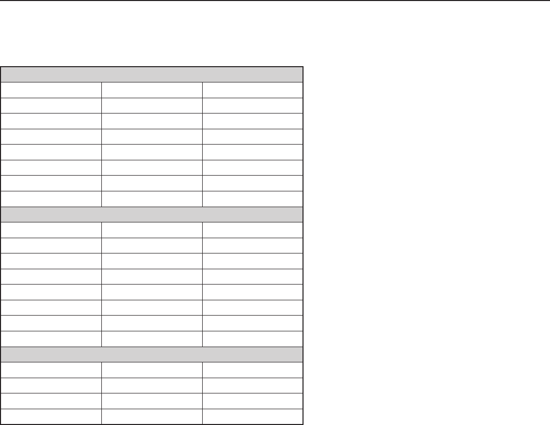
20
Scroll Heat Pump Applications*
Air Handler: Heat Pumps Piston Size
HDG18FB-1A HRG18S-1D 0.052 inch
HDG24FB-1A HRG24S-1D 0.058 inch
HDG30FB-1A HRG30S-1D 0.065 inch
HDG36FB-1A HRG36S-1D 0.068 inch
HDG42FB-1A HRG42S-1D 0.080 inch
HDG48FB-1A HRG48S-1D 0.090 inch
HDG60FB-1A HRG60S-1D 0.108 inch
Scroll Compressor Condenser Applications**
Air Handler: Condeners Piston Size
HDG18FB-1A RSG18S-1D 0.052 inch
HDG24FB-1A RSG24S-1D 0.058 inch
HDG30FB-1A RSG30S-1D 0.065 inch
HDG36FB-1A RSG36S-1D 0.073 inch
HDG42FB-1A RSG42S-1D 0.077 inch
HDG48FB-1A RSG48S-1D 0.105 inch
HDG60FB-1A RSG60S-1D 0.097 inch
Rotary Compressor Condenser Applications**
Air Handler: Condeners Piston Size
HDG18FB-1A RSG18R-1D 0.054 inch
HDG24FB-1A RSG24R-1D 0.061 inch
HDG30FB-1A RSG30R-1D 0.065 inch
*PISTON REQUIRED FOR THIS APPLICATION IS FACTORY INSTALLED.
**PISTON REQUIRED FOR THIS APPLICATION IS NOT FACTORY INSTALLED, REQUIRES
FIELD CONVERSION.
Flowrator Piston Size Chart
NOTE: Pistons are factory installed for use with HRG-1D series heat pump. To use the
coil with a RSG-1D series condenser, a piston change may be required. Refer to table below.
HDG Series Air Handler INSTALLATION INSTRUCTIONS Heat Controller, Inc.
21
9.0 AIR FILTER (not factory-installed)
• External lter or other means of ltration is required. Units should be sized for a maximum of 300 feet/
min. air velocity or what is recommended for the type lter installed.
Filter application and placement are critical to airow, which may affect the heating and cooling system
performance. Reduced airow can shorten the life of the system’s major components, such as motor,
limits, elements, heat relays, evaporator coil or compressor. Consequently, we recommend that the
return air duct system have only one lter location. For systems with a return air lter grill or multiple lter
grills, can have a lter installed at each of the return air openings.
If adding high efciency lters or electronic air ltration systems, it is very important that the air ow is
not reduced. If air ow is reduced the overall performance and efciency of the unit will be reduced. It
is strongly recommended that a profesional installation technician is contacted to ensure installation of
these such ltration systems are installed correctly.
IMPORTANT: DO NOT DOUBLE FILTER THE RETURN AIR DUCT SYSTEM. DO NOT FILTER THE
SUPPLY AIR DUCT SYSTEM.THIS WILL CHANGE THE PERFORMANCE OF THE UNIT AND RE-
DUCE AIRFLOW .
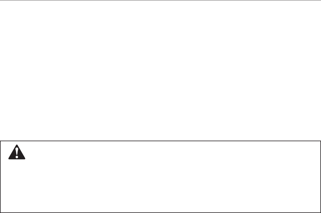
Do not operate the system without lters. A portion of the dust entrained in the air may temporarily
lodge In the duct runs and at the supply registers. Any circulated dust particles could be heated
and charred by contact with the air handler elements. This residue could soil ceilings, walls,
drapes, carpets and other articles in the house.
Soot damage may occur with lters in place, when certain types of candles, oil lamps or standing
pilots are burned.
Warning
Heat Controller, Inc. INSTALLATION INSTRUCTIONS HDG Series Air Handler
22
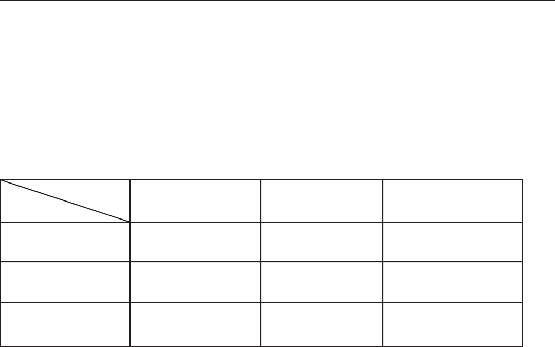
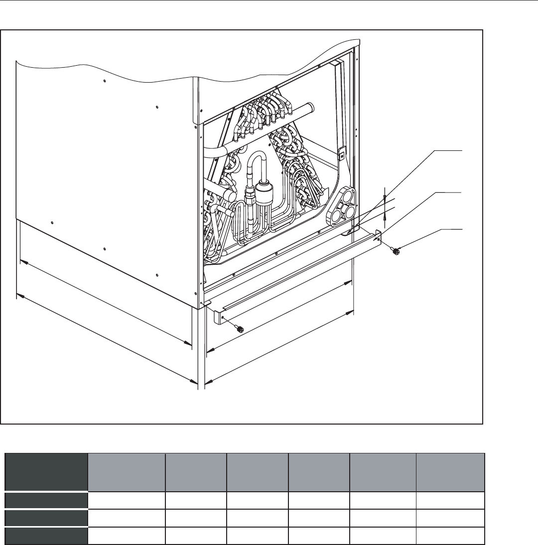
10.0 FILTER INSTALLATION DIMENSIONS
AIR FILTER REMOVAL
1.Remove bolts manually, remove air lter recover, see in Fig 7;
2. Hold the edge of the air lter and extract out .
3. Replace the lter with a properly sized lter using the table above.
NOTE:
Air filter is factory supplied (optional)
Fig. 6 EXTERNAL FILTER BASE
“H”
“W”
“B”
RETURN AIR OPENING DEPTH
“A”
“D”
FILTER RAILS
FILTER COVER
MANUAL BOLT
UNIT MUST BE SLIGHTLY INCLINED
DIMENSIONAL DATA
16.8[426] 20.4[518] 1[25.4] 19.6 14.8
18.3[466] 21.6[548] 1[25.4] 20.8 16.3
20.7[526] 23.9[608] 1[25.4] 23 18.8
"H" IN [mm] Return width
"A" IN
Return length
"B" IN
MODEL FILTER SIZE
IN [mm] "W" IN [mm] "D" IN [mm]
HDG 18/24/30
HDG 36/42
HDG 48/60
16x20 [406x508]
18x20 [457x508]
20x22 [508x559]
Fig. 7: External Filter Base
NOTE:
Air Filter is NOT factory supplied
*
* Air lter is not factory installed. Filter rack is provided. Field supplied lters must be installed per recommended sizes.
HDG Series Air Handler INSTALLATION INSTRUCTIONS Heat Controller, Inc.
23
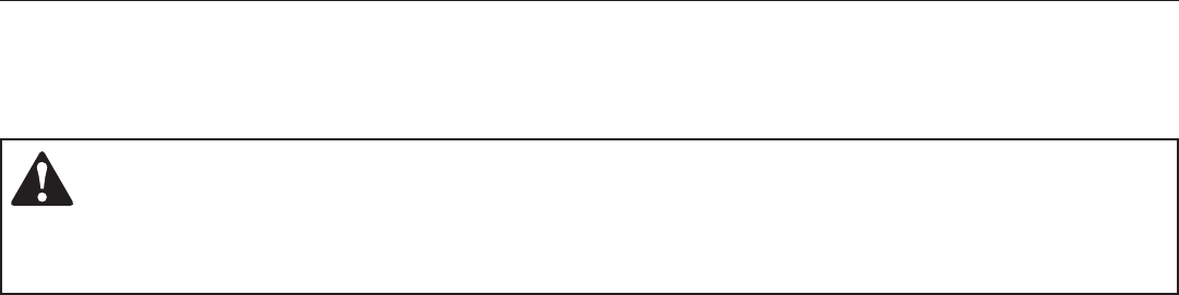
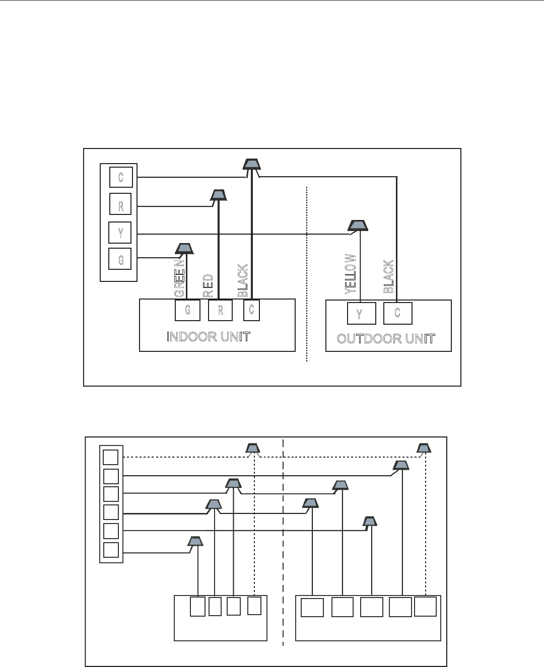
11.0 Wiring Diagram
1. To avoid the electrical shock, connect the air conditioner with the ground lug. The main power plug in
the air conditioner has been joined with the ground wiring, please don’t alter it.
2. The power socket is used as the air conditioner specially.
3. Don’t pull the power wiring hard.
4. When connecting the air conditioner with the ground, observe the local codes.
5. If necessary, use the power fuse or the circuit, breaker or the corresponding scale ampere.
THERMOSTAT
C
RED
GREEN
INDOOR UNIT OUTDOOR UNIT
Y
R
GRY
YELLOW
BLACK
BLACK
G
C
CB
R
B
RED
BLUE
W2
D
PURPLE
w1
WHITE
TH ERMO ST AT
C
R ED
YE LLO W
G REE N
Y
R
G
INDOOR UNIT OUTDOOR UNIT
G
C
Y
BLACK
R
C
BLACK
Fig. 8: Typical Thermostat Wiring for Cooling-Only Models
Fig. 9: Typical Thermostat Wiring for Heat Pump Models
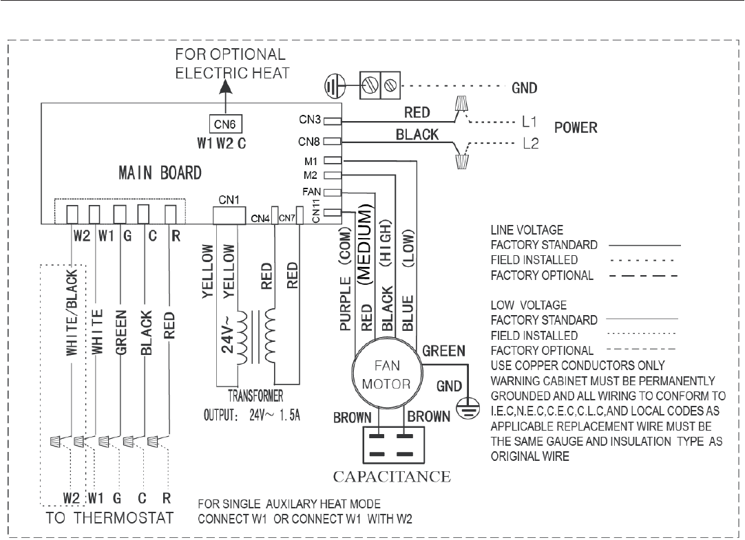
Fig. 10: Indoor Unit Wiring Diagram for A/C Systems and H/P Systems
Heat Controller, Inc. INSTALLATION INSTRUCTIONS HDG Series Air Handler
24
HDG Series Air Handler INSTALLATION INSTRUCTIONS Heat Controller, Inc.
25
0
1
2
6
4
826
48
0
1
12 GA 1015 600V 105 C
FIELD WIRING PER LOCAL CODE
6NC
PCB
1L
2L
1L
2L
0
1
2
6
4
8
6NC
PCB
0
1
2
6
4
8
6NC
PCB
10kW HEAT KIT
C
W1
W2
C
W1
C
W1
2
6
4
826
48
C
W2
W1
6NC
PCB
WHITE
5kW HEAT KIT
15kW HEAT KIT
20kW HEAT KIT
CB1(32A
NEER
G
GREEN
NEERG
GREEN
BLACK
BLACK
WHITE
0
1
0
1
C
W2
W1
WHITE
C
W1
W2
BLACK
BLACK
WHITE
BLACK
WHITE
L1
L2
L1
L2
L1
L2
L1
L2
1
L
2L
1L
2L
L1
L2
L1
L2
L1
L2
L1
L2
CB2(63A)
7.5kW HEAT KIT
7.5kW CB1 50A
10kW CB1 63A
CN3
CN8
RED
BLACK
FIELD WIRING PER LOCAL CODE
CN3
CN8
RED
BLACK
CN3
CN8
CN3
CN8
FIELD WIRING PER LOCAL CODE
FIELD WIRING PER LOCAL CODE
RED
BLACK
RED
BLACK
14 GA 1015 600V 105 C
18 GA 1015 600V 105 C
12 GA 1015 600V 105 C
14 GA 1015 600V 105 C
18 GA 1015 600V 105 C
12 GA 1015 600V 105 C
14 GA 1015 600V 105 C
18 GA 1015 600V 105 C
12 GA 1015 600V 105 C
14 GA 1015 600V 105 C
18 GA 1015 600V 105 C
BLACK
WHITE
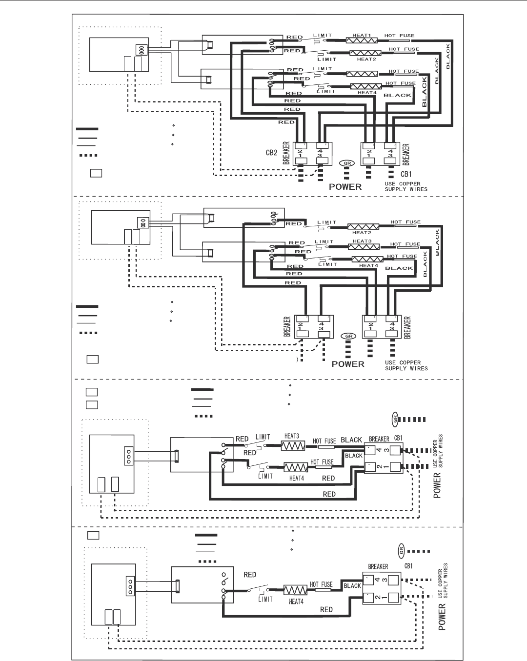
Fig. 11: Indoor Unit Wiring Diagram for Electric Heat
04/2009
05/2011
