Heatcraft Refrigeration Products Hcs Users Manual
HCS to the manual 0f1669a0-deac-4f83-8b6e-a33b9cf19ba6
2015-02-09
: Heatcraft-Refrigeration-Products Heatcraft-Refrigeration-Products-Hcs-Users-Manual-564714 heatcraft-refrigeration-products-hcs-users-manual-564714 heatcraft-refrigeration-products pdf
Open the PDF directly: View PDF ![]() .
.
Page Count: 44
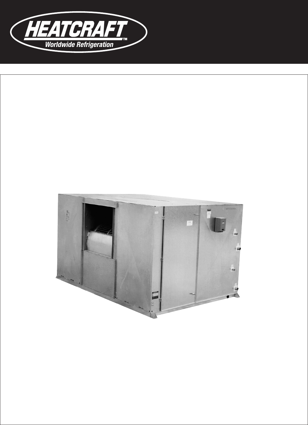
Air Handlers
Tech Bulletin
For Air Conditioning, Heating and Ventilation
Available in Bohn™, Climate Control™, Chandler™ & Larkin™
Bulletin AH-TB
January 2011
(Replaces AH-91C)
Models HCS, HCL
VCS, HD
Size 03 thru 75
2
Quick Cues for the ve cabinet styles:
S = SHORT in model HCS
L = LONG in model HCL
V = VERTICAL in model VCS
HD = HEATING DUTY in model HD
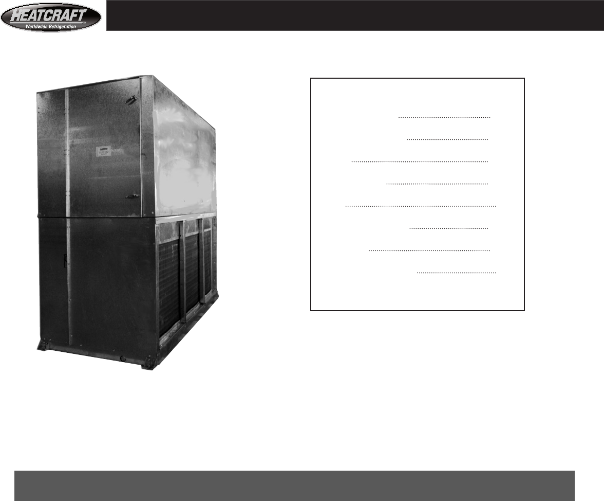
VCS MODELS 03 - 41
11 Standard Models
Capacities From
1000 to 24000 CFM
Index
Features, Accessories 3 - 10
Performance, Selection 11 - 23
Fan Data 24 - 29
Dimensional Data 29 - 38
Weight 39
Static, Air Pressure Drop 40 - 41
Physical Data 42-43
Mechanical Specications 44
Heatcraft has built high performance air handlers
for the building trade for over forty years.
Our hallmark has been a continuing process of design improve-
ments to keep pace with new system requirements. This bul-
letin presents the complete line of air handling units oered
by Heatcraft for air conditioning, heating, and
ventilation applications.
Our highest design priorities are for units with low operating costs,
rugged construction, and the features most needed for simple
trouble free installation and maintenance.
Heatcraft Refrigeration Products' ISO 9000 certication guarantees
consistent quality products for you and your customers.
Quality Standard
Index
Customers can specify brand at time of order, availabe
in Bohn, Climate Control, Chandler and Larkin.
3
Nomenclature
HCL 0 6 F C
Cabinet style Fan Type:
HCS — (S for Short) Insulated fan section with motor FC - Forward curved fans, available
base and access door(s), horizontally adjacent (same with all cabinet styles, sizes 3 thru 41
elevation) with insulated short depth coil section with
drain pan. AF - Air foil type fans, available with
sizes 20 thru 75, all cabinets except
HCL — (L for Long) Insulated fan section with motor VCS style
base and access door(s), horizontally adjacent (same
elevation) with insulated long coil section with drain pan. Nominal coil face area (square feet):
Size 03 thru size 75
VCS — (V for Vertical, fan on top of coil section) See inside back cover for actual coil face
Insulated fan section with motor base and access area for each model size.
door(s), vertically adjacent to (on top of) insulated AHV
coil section with drain pan.
HD — (HD for Heating Duty) Uninsulated fan section
with motor base and access door(s), horizontally
adjacent (same elevation) with 1, 2, 3, 4 or 6 row
heating section.
Features
‘S’ = Standard ‘A’ = Available
Standard Feature Description Unit Size
03 06 08 10 12 14 18 20 26 34 41 50 65 75
HCS (short coil section) cabinet style S S S S S S S S S S S S S A
HCL (long coil section) cabinet style S S S S S S S S S S S S S S
VCS (fan above coil section) cabinet style S S S S S S S S S S S A A A
HD (heating duty) cabinet style S S S S A A A A A A A A A A
Universal (can be oor or ceiling) mount S S S S S S S S S S S
Floor or platform mounting only S S S
16 gauge casing - fan and coil section S S S S S S S S S S S S S S
Hinged access door motor side of fan section
removable panel on opposite side S S S S S S S
Hinged access doors, both sides of fan section A A A A A A A S S S S S S S
Blower - forward curved (FC), low pressure S S S S S S S
Blower - forward curved (FC), medium pressure A A A A A A A S S S S
Blower - air foil (AF), Not available as VCS unit A A A A S S S
200,000 hour lifetime lubricated bearings S S S S S
Pillow block bearings, extended lube lines A A A A A S S S S S S S S S
Adjustable motor base S S S S S S S S S S S S S S
Left or right hand motor positions S S S S S S S S S S S S S S
Combined fan & coil sections (HCS & HCL only) S S S S S S S
Split fan & coil sections (HCS, HCL, & HD only) A A A A A A A S S S S S S S
Coil section drain pan (HCS & HCL models only) S S S S S S S S S S S S S S
Coil section drain pan (VCS models only) S S S S S S S S S S S S S S
1" by 3/4 lbs Insulation, berglass (HCS, HCL, & VCS) S S S S S S S S S S S S S S
Horizontal or vertical fan discharge arrangements,
see drawings pp.31-35 for S S S S S S S S S S S S S S
actual placement and bottom discharge
Standard Features, Basic Cabinet Models Per Unit Size
4
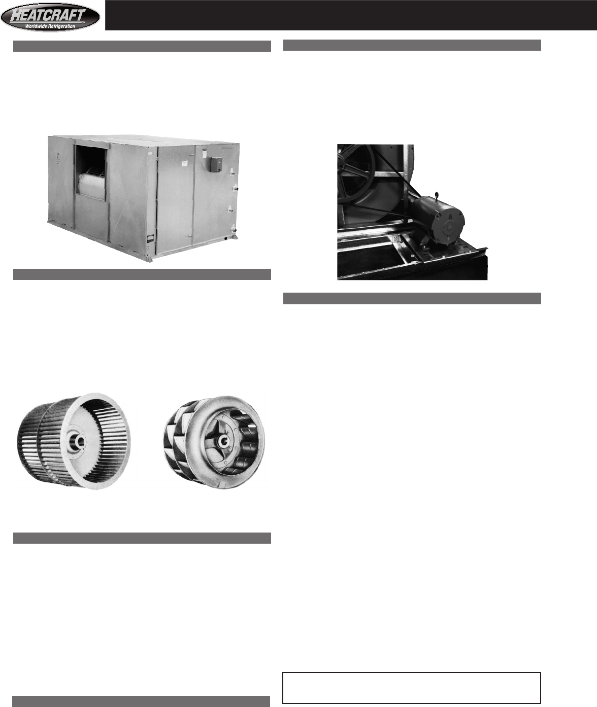
Air Foil
Fans
Forward
Curved Fans
Motor Mount
Heatcraft puts the motor inside the fan section cabinet. It is
mounted on a heavy gauge steel slide rail base. There are several
advantages with internal motor location. It eliminates the need for
a bulky belt guard. Another advantage is that Heatcraft balances
the factory mounted motor and drive components, which can
eliminate additional balancing at start-up.
Coil Section
Coil sections cover a wide range of heating and cooling
requirements. Side, top and bottom panels are 16 gauge mill
galvanized steel. All coil sections accommodate either small or
large face area coils.
The HCS coil section will hold 15 1/2" of coils and spacers. The
HCS section covers most applications. Use the HCL coil section
if the coil or access space is more than 15 1/2". (See page 38 for
maximum per model.)
Cooling coil sections have a drain pan with double wall
construction. Insulation is sandwiched between the outer panel
and the inner drain pan. The pans are heavy gauge mill galvanized
steel. Heatcraft welds the corners of the drain pans and puts drain
connections on both sides of the coil section for field convenience.
The coils sit in an upright position inside the coil section. The
air flows horizontally through the coils. Larger models (sizes 50
through 75) have cooling coils stacked two high.These larger
models come with an intermediate drain pan, so that condensate
from the upper coil does not flow over the lower coil.
Coils come in either small or large sizes (pages 42-43). A large
face area coil fills the total face area of the coil section. The
coil section’s total air volume passes through the large coil. A
small coil is shorter in height and does not fill the total face
height of the coil section. Air may bypass above the coil through
balance dampers or internal face and bypass dampers. With either
combination, it is possible to adjust and control the amount of air
passing through the small size coil.
Chilled water and direct expansion coil face velocities
over 550 FPM should be avoided--WATER CARRYOVER.
If desired, a blank off plate above the small coil can force total coil
section air volume through the small coil.
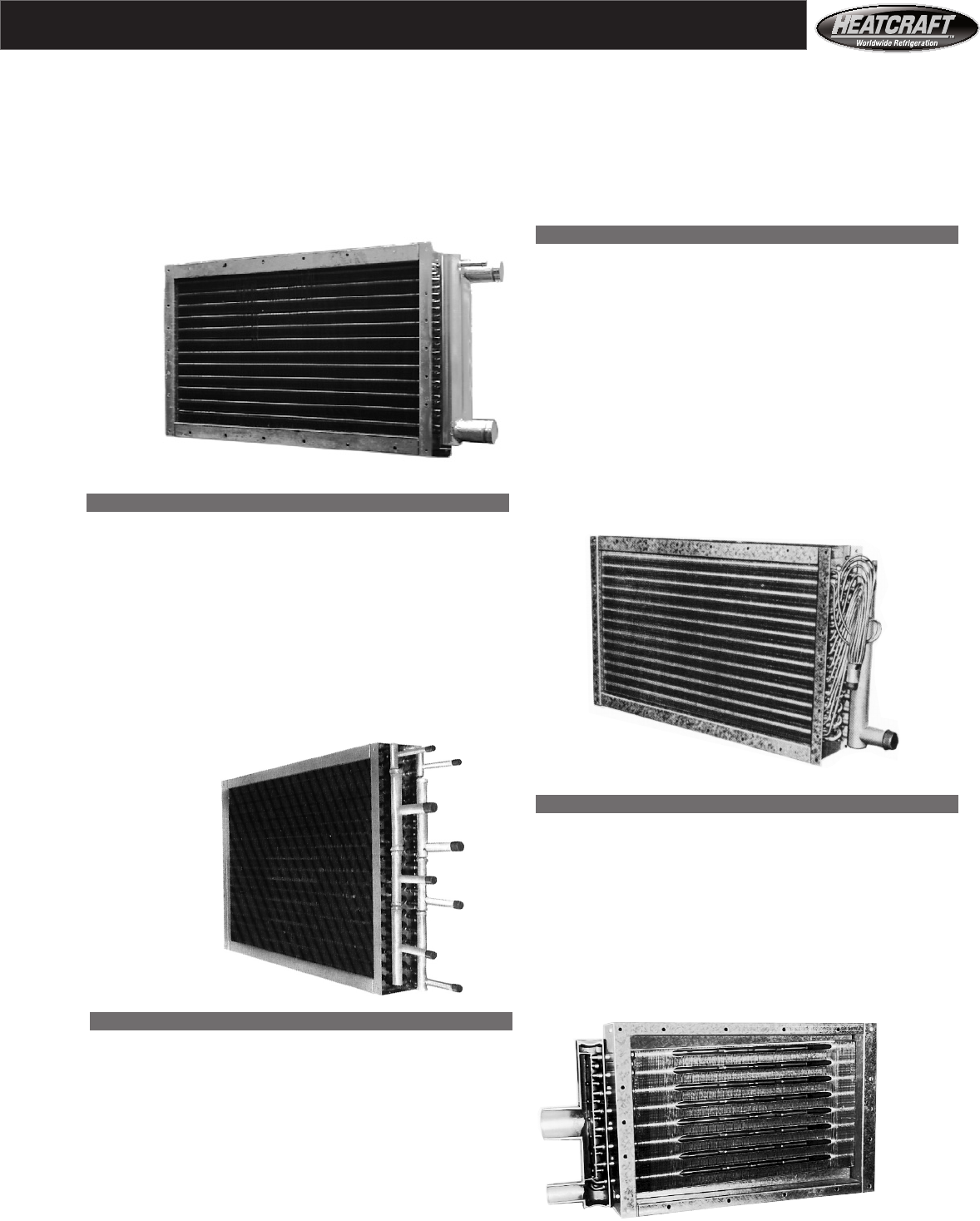
Basic Ca
Basic Cabinet
Consists of a fan section and a coil section with double wall drain
pan. The housing panels are die formed from mill galvanized steel
and insulated with 1" - 3/4 pound density mat faced fiberglass
insulation. All fan sections have hinged and latched access doors.
Unit below has fan and coil section.
Fans
All units have single, double width, double inlet fan
wheels for quiet performance and low energy consumption.
Single wheels eliminate the problem of unequal loading which is
characteristic of units with multiple wheels. Also, the expense of a
“pants” type duct connection is avoided. Sizes 03 through 41 units
have forward curved and size 50 through size 75 units have airfoil
fan as standard.
Bearings
Unit sizes 03 through 12 have lifetime lubricated fan bearings as
standard. Unit sizes 03 through 12 with optional medium pressure
fan have pillow block bearings rigidly supported on a heavy steel
frame. Unit sizes 14 through 75 have pillow block bearing rigidly
supported on a heavy steel frame as standard. The bearings are
self aligning and are selected for an average service life in excess
of 200,000 hours. There are extended lube lines and grease fittings
on the drive side of all units that have pillow block bearings. The
bearings on these models can be lubricated without opening the
blower section access door. Maximum operating temperature is
140°F.
Fan Shaft
The fan shaft is solid polished steel, and keyed for both fan and
drive. It is designed so that critical speed is at least 1.25 times the
maximum operating speed.
Standard Unit Features
5
Water Coils
A wide range of choices leads to the best coil selection for each
particular job. Select water cooling coils from 4, 5, 6, or 8 row
coil depth options. Select water heating coils from 1, 2, or 3 row
coil depth options. All water coils offer five fin densities (6, 8, 10,
12, or 14 FPI). Specify either 1/2" (Type A) or 5/8" (Type 5) tube
diameters. Heatcraft optimizes circuit design from the header into
the coil and delivers high internal heat transfer coefficients for each
application’s conditions. This is done without resorting to internal
devices which increase pressure drop or restrict draining. All circuit
designs avoid trapped circuits, so the coil is drainable. There are
vent and drain connections on both supply and return headers on
coils of 3 or more rows. All coil connections terminate outside the
air handler coil section cabinet. Design working pressure is 250
PSIG. Design fluid temperature for heating coils is 300°F.
Water
Coils
Direct
Expansion
Coils
Steam
Coils
Heat Reclaim Coils
Refrigerant Heat Reclaim (RHR) coils with multiple circuits
handle applications where a number of refrigeration compressors
are connected to a single coil. Each circuit has heavy wall
copper, sweat type, hot gas inlet and liquid or cooled gas outlet
connections. Heatcraft's custom coil circuiting maintains an internal
coil pressure drop below 5 PSIG for each system. Depending upon
job requirements select 1/2" (Type A) or 5/8" (Type 5) tube coils,
select one of five fin densities (6, 8, 10, 12, and 14 FPI), and select
from coil row depths of 2, 3, 4, 5, 6, an 8 rows.
Air Handler Coils
Direct Expansion Coils
Select direct expansion coils from 3, 4, 5, 6, or 8 row coil depth
options. All direct expansion coils offer five fin densities (6, 8, 10,
12, or 14 FPI). Specify either 1/2" (Type A) or 5/8" (Type 5) tube
diameters. Each coil has a brass, sweat connection type distributor
and copper suction header. Distributor leads of equal length work
for equal refrigerant distribution to all the circuits. Working with
Heatcraft software or your representative, select from a among
variety of circuit designs. Heatcraft has an optimum design to
deliver the proper refrigerant pressure drop for your conditions.
Specify multiple distributors for face split or row split control of
the coil.
Condenser
Heat
Reclaim
Coils
Steam Coils
Nonfreeze Steam (NFS) coils have internal steam distributing
tubes which are directionally lanced for high performance and
good condensate removal. The coils are also pitched in the coil
casing. The design working pressure and temperature of standard
copper tube coils are 150 PSIG and 366ºF. respectively. Depending
upon job requirements, select the 5/8" (Type 5) tube diameter coil
at an optimum fin spacing and a one or two row coil depth for air
handler model sizes 03 through 50. For models 65 and 75, select
the 1" (Type 8) tube diameter coil with one row at an optimum fin
spacing.
There are a wide variety of coil types to meet the load requirements of conditioned spaces. Heatcraft’s four coil types are: water, direct
expansion, heat reclaim and steam coils. All standard coils have copper tubes and aluminum fins and a heavy gauge mill galvanized steel
casing. Staggered tube designs increase air turbulence and improve coil performance. The plate type, die formed, corrugated fin design
provides optimum strength. The fin design also enhances air turbulence for peak performance. Each fin has die formed, self-spacing fin
collars which completely surround the tubes. Heatcraft mechanically expands the tubes into the fins to provide maximum heat transfer.
Fin spacing selections of six to fourteen fins per inch insure that an optimum coil is offered to meet specific design needs.
6
1. Total KW Needed
Approximate KW =
2. Number Of Steps Recommended
Rule of thumb for calculating the recommended number of
steps required. Use Step A or B below, whichever is higher.
A. Number of Steps =
(Based on approx. 10°F. temp. rise per step)
B. Number of Steps =
CFM x TD (F)
3000
300 x Total Heater KW
CFM
Total Heater KW
Maximum KW per step
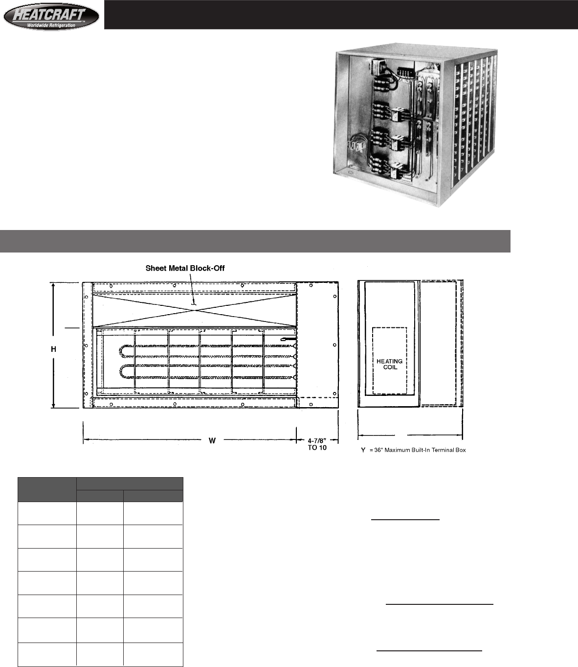
Electric heaters are UL listed for duct installation. The UL
label applies to the heater only, not the complete air handler.
Heaters are furnished as a separate section and are available
with insulated or uninsulated casings. Controls such as
contactors, fuses, etc., may be factory installed and wired in
the heater section end panel provided the number of control
steps is not excessive.
Remote control panels are also available.
Y
Construction & Dimensions
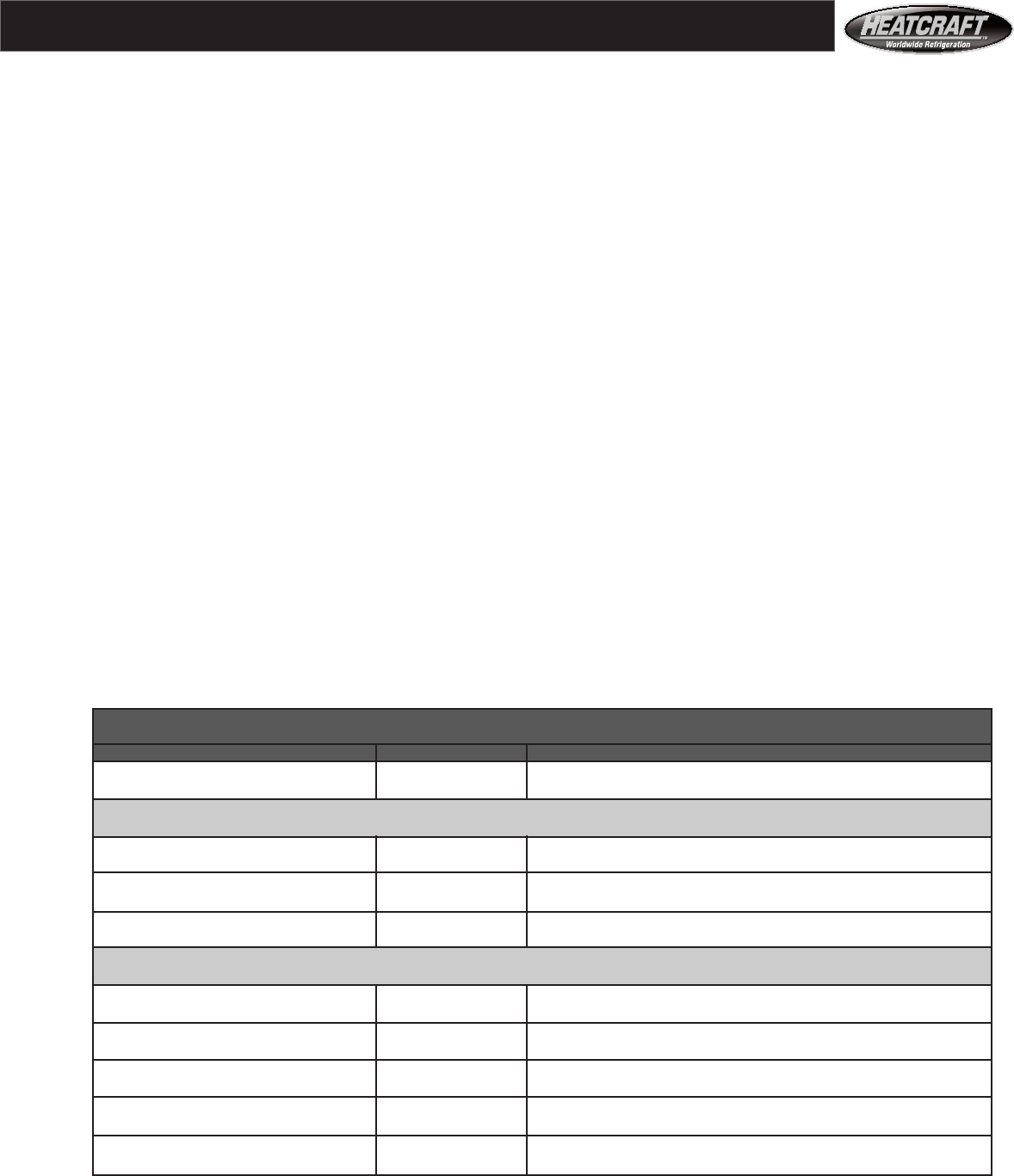
Accessories- Electric Heat
Unit Heater Dimensions (In.)
Size H W
03 22 3/4 30 5/8
06 26 45 5/8
08 35 1/2 42 5/8
10 35 1/2 51 5/8
12 38 3/4 57 5/8
14 38 3/4 66 5/8
18 47 3/4 66 5/8
20 44 83 5/8
26 44 108 5/8
34 54 108 5/8
41 65 108 5/8
50 74 3/4 110 7/8
65 82 3/4 126 7/8
75 94 3/4 126 7/8
Notes: Heaters for constant volume units to have 35 W/in2 of wire
surface maximum.
7
1. Automatic thermal cutout
2. Heat limiters
3. Air flow switch
The standard electric heater section construction Typical options for the electric heater
includes: section are:
Maximum KW per
contactor and per fuse
block (at least one
contactor is required per
step of heating):
Notes:
1. You must order the split shipment of the fan
and coil sections to get electric heat on unit
size 03 through unit size 18.
2. All electric heat controls are built into the heater
control box.
3. Specify two pole break contactors or three pole
break contactors. Two pole contactors only
de-energize, while three pole contactors
disconnect.
4. Be aware of requirements for heater circuits
rated more than 48 amps. According to
N.E.C. Code and U.L. you must subdivide
the heater elements of such circuits. N.E.C.
Code requires that the sub-circuit fuses be
furnished by the heater manufacturer.
1. Fiberglass insulation in cabinet
2. At least one magnetic contactor per step of
heating (two or three pole break)
3. Three phase fuse blocks and fuses
4. Transformer with primary fusing
5. Manual reset thermal cutout in control circuit
Commonly Used Control Systems:
A. For small loads (up to 20 KW),consider a
multi-stage thermostat.
B. For medium loads (up to 200 KW), consider a
modulating thermostat that operates a step
controller.
C. For fine control of large loads (above 75 KW),
consider a combination step control and SCR
vernier system. This scheme has 80% of heater
capacity controlled by conventional step controller,
with the other 20% on a solid state SCR controller.
D. For 100% proportional control of any size,
consider a total SCR control.
E. Heatcraft does not supply :
multi-stage thermostats
modulating thermostats
But you will want to order contactors and fuse
blocks from Heatcraft that are appropriate for
for the control scheme specified in the field.
Accessories- Electric Heat
Maximum KW
Component 208 V 240 V 460 V 480 V
Low amps contactor 9.0 10.4 19.9 20.8
High amps contactor 17.3 19.3 38.2 39.9
Fuse block 17.3 19.9 38.2 39.9
Electric Heater Selection Example
A. How many KW is needed to increase temperature of 17000 CFM by 27 °F for Air Handler Model Size 34?
17000 X 27 is: 153 KW IS REQUIRED
3000
B. How many steps required at 10°F rise per step?
300 X 153 is: 2.7 STEPS ROUNDS UP TO 3 STEPS
17000
C. How many steps required at 460 volts with low amps contactors?
153 is: 7.7 STEPS ROUNDS UP TO 8 STEPS
19.9
D. How many steps required at 460 volts with high amps contactors?
153 is: 4.0 STEPS
38.2
E. How many fuse blocks required?
153 is: 4.0 FUSE BLOCKS
38.2
°F. Order the 153 KW to get the 27 degree rise.
Throw out the 3 steps (figured at 10°F. rise in part B), because it is smaller than the two values figured
per contactor size (parts D & E). Decide whether you want high amps or low amps contactors, if you
want low amps contactors, round the 7.7 to 8 and order 8 of the low amps contactors (you now have a
possible 8 steps of control). If four steps of control are satisfactory, order the high amps contactors. In
either case, the application requires four fuse blocks (part E).
8
Accessories
Face
and
Bypass
Dampers
Face And Bypass Dampers
For damper applications, choose either the internal face and bypass
section or the external face and bypass section. If used with a
large coil the damper section must be the external face and bypass
damper type. When used with a small coil, select the internal face
and bypass damper section. The damper sections have balanced
opposed blades with interconnecting linkage. The blades positively
lock to the damper shafts. The shafts rotate freely in frictionless
sleeve bearings.
Mixbox
Mix Box Sections
The Mixbox is an entering air section. Typically, themixbox
accepts air from two sources. Many system designers economize
performance by varying the two air flows to deliver conditioned
air with minimum energy consumption. Mixbox sections are
constructed with heavy gauge mill galvanized steel. Select from
three inlet opening locations: the air can enter through openings
at the top, at the back, or at the bottom of the section. Order the
mixbox with or without dampers. The section with dampers has
parallel blades at each opening and an interconnecting linkage
between the openings. The damper rods rotate in frictionless
sleeve bearings, and the drive rod extends from both sides of the
section for either left or right hand drive.
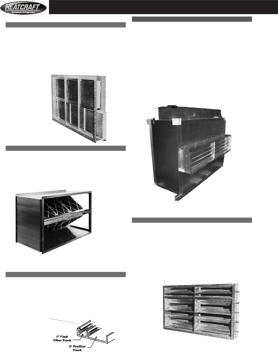
Flat Filter Sections
Flat filter sections are space saving and economical. Choose
either two inch or four inch filters. The two inch filters can be the
throwaway, the 35% pleated, or the high velocity cleanable type.
Four inch filters are 35% pleated, they have more filter surface
than two inch filters. Four inch filters impose less static on air flow
and do not need to changed as often as two inch filters. The filters
slide into metal channels and are removable from either side of the
section.
Flat Filter Section
High Capacity Filter Sections
Designed for high air volume applications. Filters are arranged in
a V or W pattern for the greatest surface possible which provides
extended filter life and reduced resistance to air flow. This means
less fan horsepower. The sections have access doors on each side
to ease filter change.
High Efficiency Filter Sections
High Efficiency Filter Sections
Select 22", 28", or 44" bag filter sections. Choose medium or high
efficiency bag or cartridge filters for this section. See pages 9,
29, 42, and 43. Sections are complete with prefilter and bag filter
tracks. The sections have an extruded aluminum final filter track
with a reinforced nylon pile seal. The postive seal forces the air
flow through the high efficiency final filter.
High capacity
Filter Section
Extruded Aluminum
Filter Track
Final Filter Tracks Have
Reinforced Nylon Pile
For A Postive Seal
9
Flat and High Capacity Filter Sections- All Unit Sizes: (Dimensions, Page 29 to 37)
High Effeciency Filter Sections- All Unit Sizes: (Dimensions, Page 29 to 37)
Auxilary Sections- All unit Sizes: (Dimensions, Page 29 to 37)
Accessories
Filters And Auxiliary Sections
(see pages 42 and 43 for number and quantity of filters per model)
2" flat filter section with choice of three standard filter types:
• 2" throwaway filters
• 2" 35% efficient pleated filters
• 2" permanent high velocity cleanable filters
4" flat filter section:
• with 4" 35% efficient pleated filters
High capacity filter section with choice of three standard filter types:
• 2" throwaway filters
• 2" 35% efficient pleated filters
• 2" permanent high velocity cleanable filters
Prefilters: select either 2" throw-away or 2" 35% efficient filters as prefilters. All three high
efficiency filter sections accept prefilters, without reducing final filter depth capacity.
• 2" high efficiency filter section (accommodates up to 12" of final filter depth):
• Prefilter and either 6"or 12" cartridge filters at 60% to 65%, or 80% to 85%,
or 90% to 95% efficiency
• 28" high efficiency filter section (accommodates up to 21" of final filter depth):
• Prefilter and 21" bag filters at 60-65%, or 80-85%, or 90-95% efficiency
• 44", high efficiency filter section (accommodates up to 37" of final filter depth):
• Prefilter and 30" bag filters at 60% to 65%, or 80% to 85%, or 90% to 95% efficiency
• OR prefilter and thirty-seven inch bag filters at 60% to 65%, or 80% to 85%, or 90% to 95% efficiency
High efficiency filter section options:
• 1" depth by 3/4 lbs per cu. ft. density fiber glass insulation (standard section not insulated)
• Diffuser section, must be used when high efficiency filter section is downstream of fan (blow-through unit)
• Double wall construction on high efficiency filter section, adds 4" to the width and 2" to the height of the unit.
Insulation is 2" depth and 1.5 lbs per cu. ft. fiberglass. The insulation is sandwiched
between standard unit and outer skin.
• Mixbox section, without dampers, with top, bottom, or back inlet openings,
• HCS type coil module, includes insulation, drain pan and four mounting legs, 15.5" max coil depth, see page 38.
• HCL type coil module, includes insulation, drain pan and four mounting legs, and more coil depth, see page 38.
• internal face and bypass sections, must be used with small coil for air bypass. See page 8.
• external face and bypass section, must be used with HCL type coil section or module. See page 8.
• Insulated access section, same size as high capacity filter section, hinged and latched doors, both sides.
• Uninsulated access section, same size as high capacity filter section, hinged and latched doors, both sides.

10
* The percentage means the belts can handle an extra 20% or 50% BHP.
Available on:
Available on:
Accessories for Fan and Coil Sections
Fan Section Accessory:
Forward curved blower for total static of 3.5" to 6" ........................................................................Models 03 - 18 for all cabinet styles
Internal spring isolation (discharge arrangement 2 and 3 only).......................................................All models except size 14 and VCS cabinets
Internal spring isolation (discharge arrangement 2, 3, 4, 5 only) ....................................................All VCS cabinets except size 14
Inlet vanes (does not include damper motor), forward curve (FC) ..................................................Models 20 - 41 for all cabinet styles
Inlet vanes (does not include damper motor), air foil (AF) fan .......................................................Models 20 - 75 for all cabinet styles
Dual drive (extended shaft blowers with motors and drives
installed on each side of fan, select 2 motors and 2 drives .........................................................Models 20 - 75 for all cabinet styles
Coil Section Accessory: Available on:
Large face area and small face area coils (see pages 42 & 43) ........................................................All HCS, HCL, HD, and VCS coil cabinets
Balancing dampers above small coil (to adjust air flow over coil in the field) ................................All HCS, HCL, HD, and VCS cabinets
Blank off plate above small sized coil (to force entire air flow over coil) .......................................All HCS, HCL, HD, and VCS cabinets
Stainless steel drain pan (in coil sections)....................................................................................... All HCS, HCL, HD, and VCS coil cabinets
Coil section access door (standard section has removable panels) ..................................................All HCL and VCS coil cabinets
Coil spacer, a preheat coil can be spaced apart from a cooling coil with a
coil spacer, the spacer prevents air bypass around the downstream
coil. The standard spacer is 6" wide and is furnished with a 4" x 6" .......................................All HCL and VCS coil cabinets
removable inspection plate. See below for reheat coil.
Mount reheat coil to leaving air side of section (see page 38).................. .......................................All HCL and VCS coil cabinets
Gaskets
Gaskets between sections......................................................................................... ........................All HCS, HCL, HD, and VCS cabinets
Gaskets between sections and gasketed panels (outdoor application)..........................Available on all five cabinets
Double Wall:
Double wall construction, adds 4" to the width and 2" to the height and length of
cabinet. Insulation is 2" of fiberglass at 1.5 lbs per cubic foot density. Available on all five
The insulation is sandwiched between the standard unit and the outer skin. fan and coil cabinets
Motors are three phase, ball bearing, rigid base and belt duty.
‘A’ = Available
Available Motors, Drives, Motor Starters per Horsepower
Motor Drive* Starter Motor Horsepower
Description 1 1.5 2 3 5 7.5 10 15 20 25 30 40 50
Open single speed motor, EPAct A A A A A A A A A A A A A
Totally enclosed fan cooled (TEFC) motor, EPAct A A A A A A A A A A A A A
Open 2 speed 2 winding, 1800-1200 RPM motor A A A A A A A A A A
Open single speed premium high efficiency motor A A A A A A A A A A A A A
Fixed drive - at a 120% Safety Factor of HP A A A A A A A A A A A A A
Fixed drive - selected at a 150% SF of HP A A A A A A A A A A A A A
Adjustable drive - selected at a 120% SF of HP A A A A A A A A A A
Adjustable drive - selected at a 150% SF of HP A A A A A A A A A A
Motor starter at 460/3/60, 120 volt holding coil A A A A A A A A A A A A A
Motor starter at 230/3/60, 120 volt holding coil A A A A A A A A A A A
Motor starter at 200-208/3/60, 120 volt holding coil A A A A A A A A A A
11
Air Handler Selection
1. Air handler selections vary with each application. Use the index below to find Heatcraft Products air handler
performance tables for:
• Standard comfort cooling (either direct expansion or chilled water)
• Heating (either steam or hot water, either make up air or return air)
• Supermarket air conditioning (direct expansion refrigerant)
• Heat reclaim (coil performance, refrigerant condenser, typically supermarket)
2. The air handler performance tables give ARI ratings for the specific applications, conditions and coils
listed. All performance tables (except reclaim) rate: 10 FPI coils at 500 FPM coil air velocity.
To select air handlers for other applications, conditions, or components:
• Call your representative. With your representative, you can have specific
computer selected coils rated for your job conditions.
• Use tables on pages 21 to 23 for estimates of coil performance at various
conditions.
3. See page 12, step 5 to calculate total static pressure. Consult fan tables, pages 24 to 29 and
select fan motor.
4. Heatcraft builds each air handler to your components specifications.
Please specify the following as needed with your order:
• CFM
• External or total static pressure
• Motor HP, motor type, motor voltage, motor location (left hand or right hand)
• Describe coils or specify with Heatcraft Products model numbers.
Coil description can include:
Rows, FPI, refrigerant, design capacity (BTUH),
Number of circuits, coil location inside air handler (preheat, reheat, etc.)
Location of coil connections (left hand or right hand)
• Filter sections and filter types
• Vibration isolators
5. Go to page 12 for air handler selection example.
Application & Table Coil Type Selection Conditions
Heating and cooling Refrigerant Selected conditions for each coil type presented
Table 1 “Quick Reference”, page 13 Water & Steam in a single table. See Table 1 notes for conditions.
Cooling:
Standard comfort cooling DX Refrigerant 80°F. DB entering air 35°F., 40°F., and
Tables 2 & 3, page 14 4 & 6 Row Coils 67°F. WB entering air 45°F. evaporating temp
Supermarket air conditioning DX Refrigerant 75°F. DB entering air 35°F., 40°F., and
Tables 4 & 5, page 15 4 & 6 Row Coils 63°F. WB entering air 45 °F. evaporating temp
Standard comfort cooling Chilled Water 80°F. DB entering air 42°F. ,44°F., 45°F. entering
Tables 6 to 9, page 16 4 & 6 Rows 67°F. WB entering air water temperature
Heating:
Refrigerant Hot Gas Reclaim Refrigerant 2, 3, 50°F. Temperature Difference Between Condensing
Table 16 page 20 4, 6, 8 Row Coils Temperature and Coil Entering Air Temp.
Preheating, Tempering Hot Water 0 °F. entering air 180°F. entering water and
Tables 10 & 11, page 18 1 & 2 Rows 200°F. entering water
Preheating, Tempering Steam 0°F. entering air 5 PSIG steam*
Table 11, page 18 1 Row Only
Heating Return Air Hot Water 60°F. entering air 180°F. entering water
Tables 12 & 13, page 19 1 & 2 Rows 200°F. entering water
Heating Return Air Steam 60°F. entering air 5 PSIG steam*
Table 13, page 19 1 & 2 Rows
* Steam coils for model sizes 65 and 75 have a 1" tube diameter.
Index To Air Handler Performance Tables - Typical Applications & Coil Selections

Selection Procedure:
12
1. Which air handler for cooling performance?
Look at index of air handler performance
on page 11. Find that tables 6 through 9
give chilled water performance. You need 35 tons or 35 x 12 = 420 MBH
Compare 1/2" and 5/8" and 4 row and 6 row performance:
Select size 20 air handler with six row 1/2" tube coil with capacity of: 430 MBH
Note that 4 row 5/8" tube coil is not enough at: 374 MBH
2. Which air handler for heating performance?
Look at index of air handler performance on
page 11. Find that tables 12 & 13 are for hot
water performance with 60°F. air. You need 35 tons or 35 x 12 = 420 MBH
Compare 1/2" and 5/8" and 1 row and 2 row performance:
Select one row 5/8" tube coil for size 20 air handler with capacity of: 502 MBH
Note that 1 row 1/2" tube coil is much too small at capacity of 395 MBH
3. Comparing steps 1 & 2, select:
Size 20 air handler at 10025 CFM with
6 row, 1/2" tube chilled water coil with
1 row, 5/8" tube hot water coil.
4. Look at page 38, “Characteristics of standard coil sections “ and confirm that:
1 row depth coil casing: 3.25 inches
+ 6 row depth coil casing: +9.75 inches
Total 13.00 inches fits into HCS type cabinet
5. Look at page 40 & 41, “Air pressure drop tables” and calculate total pressure drop:
0.17 inch Pressure drop through 1 row coil, see dry 5/8" tube at: 10025 Divided By 19.25 = 521 FPM
0.79 inch Pressure drop through 6 row coil see wet 1/2" tube at: 500 FPM
0.22 inch Pressure drop for flat filter section, pleated 2" filter at: 10025 Divided By 24.4 = 411 FPM
+ 0.50 inch External static pressure
1.68 inch Total static pressure
6. Look at page 27, “Fan performance”:
Select a 5 HP motor for the condition of 10000 CFM and less than 1.75 inches of water.
7. Air handler description and performance:
Description: Performance:
HCS model size 20 10025 CFM at 1.68" total static and
with 6 row 10FPI, type A, cooling coil 0.5" external static pressure
with 1 row 10 FPI, type 5, heating coil 430 MBH total cooling capacity and
with open 5 HP motor at 230/3/60 volts 292 MBH sensible cooling capacity with
(See page 10) 80°F. DB/ 67°F. WB entering air
with 120% adjustable drive and 44 °F entering water at
with motor starter 85.8 GPM and 13.5 feet of
with flat filter section fluid pressure drop
with 35% efficient 2" filters 502 MBH of heating capacity with
with (6) rubber in shear vibration isolators 60°F. entering air and 200°F.
for ceiling mount (see page 38) entering water at 64.5 gpm
and 12.3 feet of fluid pressure drop
8. To estimate performance of coils at other than 10 FPI, or different row depths, or different air speeds or
temperature conditions see tables on page 20 - 23, or call your representative. With your representative,
you can have specific computer selected coils for your job conditions.
Selection Example
Air Handler Selection Conditions:
“I want a ceiling mounted air handler that gives 35 tons of cooling and 35 tons of heating. I have 44°F. water for
cooling and I have 200°F. water for heating. My entering air temperatures on the coil are standard, that is 80°F. dry bulb and 67°F. wet
bulb (50% relative humidity) for cooling. For heating, the entering air temperature is 60°F. I will supply duct work,
you should select the motor to handle a half inch of external static pressure. Select the smallest air handler possible and tell me what kind
of CFM, flow rates, fluid pressure drops, and sensible cooling performance your selection will give me. I want a filter too.”
13
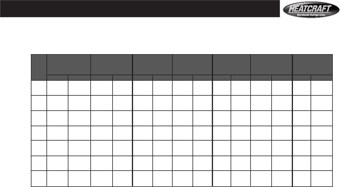
Table 1 Heating and Cooling Performance for Selected Coils
At 500 FPM (2.54 m/s) and 10 FPI.
See notes for coil descriptions and rating conditions.
Notes
Note 1 - Air volume in CFM and cubic meters per hour for air speed of 500 fpm or 2.54 meter per second
through a large face area 1/2" tube diameter (Type A) coil for each air handler model.
See pages 42 & 43 for range of air volumes for each model.
Note 2 - Face area of large size 1/2" diameter tube coil for each air handler in square feet and square meters.
5/8" & 1" diameter tube coils have slightly smaller face areas. See page 42 & 43 for other coils.
Note 3 - Direct expansion halocarbon air conditioning in thousands of BTUH and kilowatts. Performance is for a
1/2" tube, 4 row, 10 FPI coil with 40°F. (4.4ºC.) evaporating temperature and entering air
temperatures at 80°F. (26.7ºC.) dry bulb and 67°F. (19.4ºC.) wet bulb. See pages 14, 15, and 21 for
other coils and conditions.
Note 4 - Halocarbon refrigerant gas heat reclaim (thousands of BTUH and kilowatts). Performance is for a 1/2"
tube, 3 row, 10FPI coil with a 50°F. TD (or 27.7 degrees centigrade of temperature difference)
between entering air and condensing temperature. See page 20 for other coils and conditions.
Note 5 - Chilled water air conditioning in thousands of BTUH or kilowatts. Performance is for a 5/8" tube, 6
row, 10FPI coil with 44°F. (6.7ºC.) entering water temperature. Entering air temperatures are 80°F.
(26.7ºC.) dry bulb and 67°F. (19.4ºC.) wet bulb. The fluid pressure drop is less than 25 feet (0.76
kilogram per square centimeter) and the water velocity is less than 6 fps (1.83 meters per second).
See pages 16,17,and 22 for other coils and conditions.
Note 6 - Hot water heating performance in thousands of BTUH or kilowatts. Performance is for a 5/8" tube, 2
row, 10 FPI coil with 200°F. (93.3ºC.) entering water temperature. The entering air temperature is 0°F.
(-18°C.). The fluid pressure drop is less than 25 feet (0.76 kilogram per square centimeter) and the water
velocity is less than 6 fps (1.83 meters per second). See pages 18, 19, and 23 for more coils.
Note 7 - Steam heating performance in thousands of BTUH or kilowatts. The coils are 5/8" tube, 1 row, and 10
FPI (coils for models 65 and 75 are 1" diameter tubes). The entering air temperature is 60°F. (15.6ºC.)
and the steam pressure is 5 psig (1.38 kilogram per square centimeter). See pages 18, 19, and 23 for
other coils and conditions.
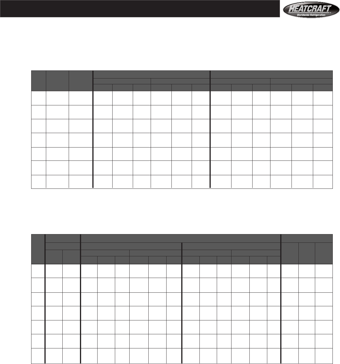
Air Handler Performance - Quick Reference
Note 1 Note 2 Note 3 Note 4 Note 5 Note 6 Note 7
air volume at air handler DX air Refrigerant Chilled water Hot water Steam
Unit 500 fpm 2.54 m/s face area conditioning Heat reclaim A/C Heating Heating
Size CFM cu m/h SQ FT sq m MBH KW MBH KW MBH KW MBH KW MBH KW
03 1565 2659 3.13 0.29 58 17.0 50 14.7 73 21.4 177 51.9 93 27.3
06 2880 4893 5.76 0.54 110 32.2 92 27.0 136 39.9 341 99.9 179 52.4
08 3905 6635 7.81 0.73 150 44.0 124 36.3 179 52.5 452 132.4 254 74.4
10 4885 8300 9.77 0.91 190 55.7 156 45.7 229 67.1 548 160.6 317 92.9
12 6200 10534 12.40 1.15 241 70.6 198 58.0 286 83.8 684 200.4 395 115.7
14 7290 12386 14.58 1.36 284 83.2 232 68.0 328 96.1 812 237.9 465 136.2
18 8855 15045 17.71 1.65 345 101.1 282 82.6 418 122.5 1034 303.0 571 167.3
20 10025 17033 20.05 1.86 390 114.3 319 93.5 472 138.3 1162 340.5 651 190.7
26 13280 22563 26.56 2.47 520 152.4 423 124.0 616 180.5 1520 445.4 859 251.7
34 16825 28586 33.65 3.13 659 193.1 536 157.1 814 238.5 2026 593.6 1145 335.5
41 20365 34601 40.73 3.79 797 233.5 649 190.2 978 286.6 2406 705.0 1360 398.5
50 25313 43008 50.63 4.70 992 290.7 807 236.5 1196 350.4 2637 772.6 1586 464.7
65 32290 54861 64.58 6.00 1253 367.1 1029 301.5 1549 453.9 3798 1112.8 1848 541.5
75 37675 64011 75.35 7.00 1462 428.4 1200 351.7 1792 525.1 4407 1291.3 2156 631.7
14
SST = Saturated Suction Temperature All coils have single refrigerant distributors unless noted as below:
MBH = BTU per Hour in Thousands ^ These selections require two circuits.
Sens. = Sensible Capacity ^^ These selections require three circuits.
* These selections require four circuits.
** To estimate performance of coils at other than 10 FPI or at other air speeds or with other refrigerant or air
temperatures see page 21, or call your representative. With your representative, you can have specific computer
selected coils rated for your job conditions.
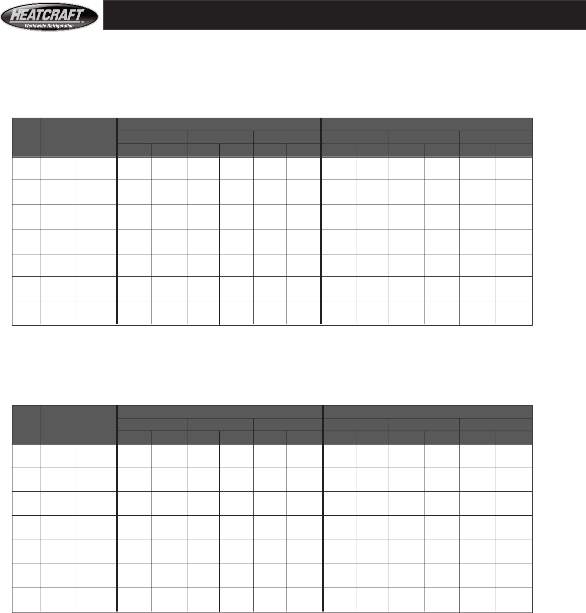
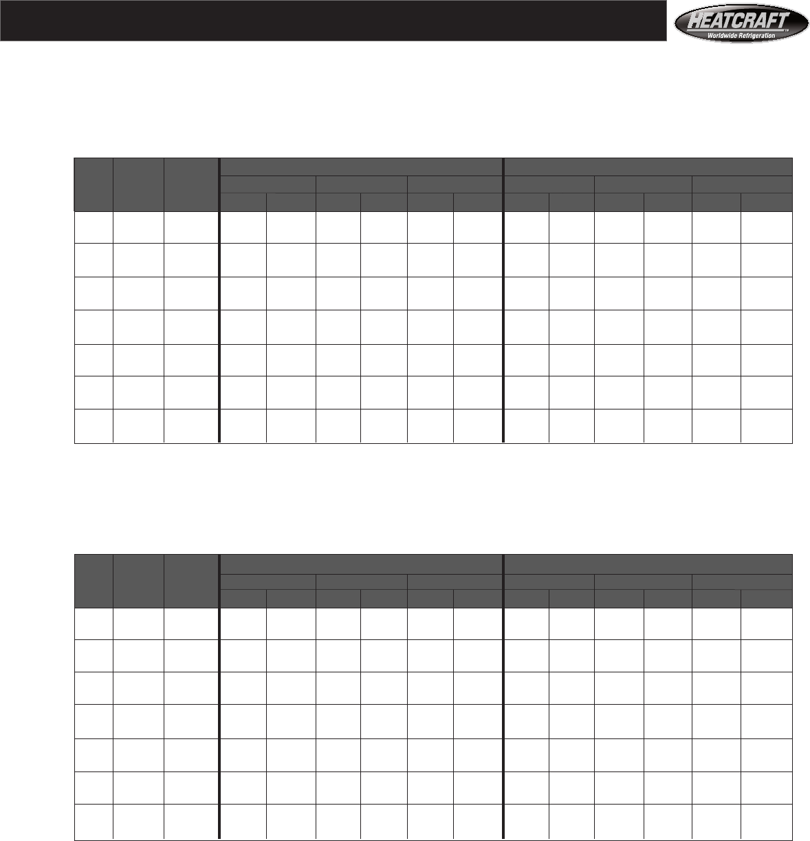
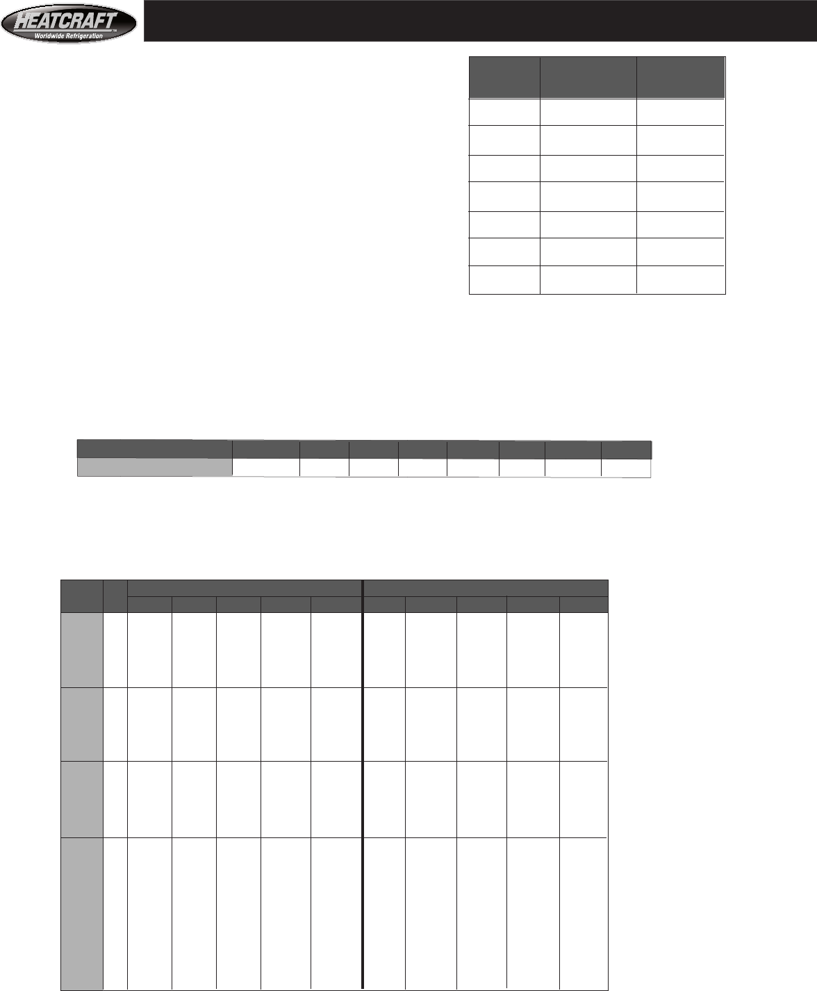
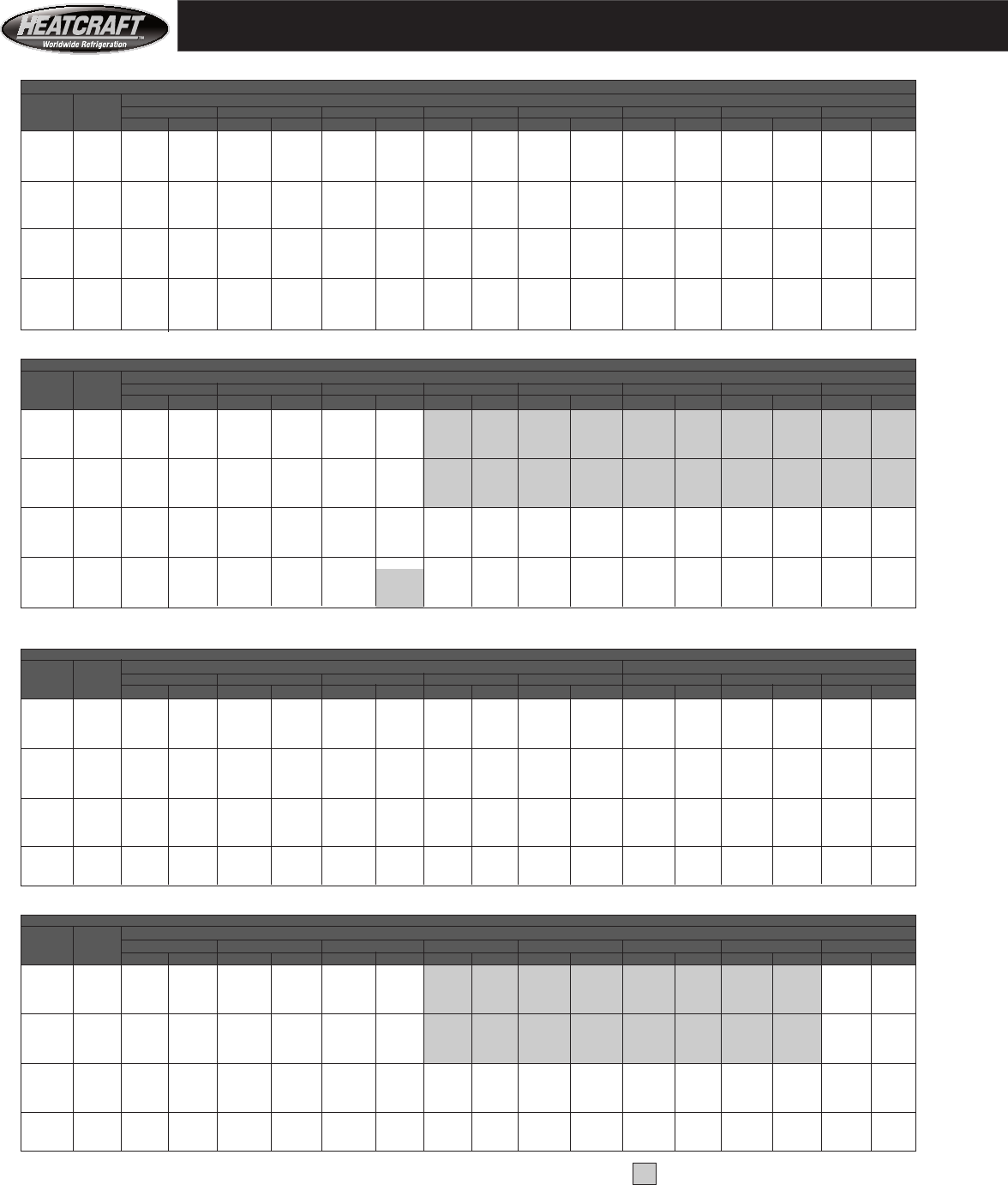
Table 3
Comfort Cooling
5/8" tube, entering air at 80°F. DB and 67°F. WB**
5/8" Tube, direct expansion, cooling capacities
10 FPI**, large coils, 500 FPM**
Table 2
Comfort Cooling
1/2" tube, entering air at 80°F. DB and 67°F. WB**
1/2" Tube , direct expansion, cooling capacities
10 FPI**, large coils, 500 FPM**
Air Handler Performance- Direct Expansion
CFM Coil MBH - 4 ROWS MBH - 6 ROWS
Unit Std Face 35°F. SST 40°F. SST 45°F. SST 35°F. SST 40°F. SST 45°F. SST
Size Air Area Total Sens. Total Sens. Total Sens. Total Sens. Total Sens. Total Sens.
03 1565 3.13 70 44 58 38 44 33 87 53 75 48 61 42
06 2880 5.76 132 81 110 72 90 64 163 99 138 88 114 78
08 3905 7.81 177 110 150 99 123 88 219 133 189 119 154 105
10 4885 9.77 224 139 190 125 152 109 278 168 235 150 192 131
12 6200 12.40 284 177 241 157 194 140 353 214 301 191 242 166
14 7290 14.58 336 207 284 187 231 165 416 253 354 225 290 197
18 8855 17.71 408 250 345 226 280 201 505^ 308 428 272 352 242
20 10025 20.05 459 282 390 256 319 226 568 343 489 308 399 273
26 13280 26.56 614 379 520 338 418 300 762^ 461 648^ 411 524 358
34 16825 33.65 778^ 480 659^ 428 530^ 380 966^ 584 821^ 520 664^ 454
41 20365 40.73 942^ 581 797^ 518 641^ 460 1168^^ 706 994^^ 630 804^ 549
50 25313 50.63 1169^ 721 992^ 648 803^ 577 1488* 875 1239* 788 1002* 686
65 32290 64.58 1447^ 905 1253^ 827 1035^ 742 1820* 1104 1574* 995 1293* 884
75 37675 75.35 1689* 1056 1462* 965 1208* 866 2124* 1288 1836* 1161 1509* 1032
CFM Coil MBH - 4 ROWS MBH - 6 ROWS
Unit Std Face 35°F. SST 40°F. SST 45°F. SST 35°F. SST 40°F. SST 45°F. SST
Size Air Area Total Sens. Total Sens. Total Sens. Total Sens. Total Sens. Total Sens.
03 1500 3.00 75 47 62 42 48 37 88 54 76 49 63 43
06 2844 5.69 138 88 111 77 84 67 173 105 147 94 118 81
08 3750 7.50 178 114 157 106 129 95 228 139 192 122 152 106
10 4690 9.38 234 148 192 130 157 116 283 173 244 156 198 136
12 5844 11.69 296 186 246 165 192 144 346 212 301 192 249 169
14 6875 13.75 349 220 295 196 235 172 412 253 345 221 290 199
18 8750 17.50 444 280 375 249 299 219 536 326 455 289 369 254
20 9625 19.25 467 297 408 273 335 245 591 360 500 317 412 279
26 12750 25.50 651 408 540 362 422 314 779^ 475 665 421 547 371
34 17000 34.00 868^ 544 720^ 482 563 418 1039^ 633 886^ 562 729^ 495
41 20188 40.38 1030^ 646 855^ 573 669 497 1234^ 752 1052^ 667 866^ 587
50 24750 49.50 1268^ 790 1059^ 709 830^ 610 1520* 923 1282^ 817 1062^ 722
65 32292 64.58 1651^ 1032 1401^ 933 1116^ 809 1989* 1212 1692* 1067 1369^ 937
75 37458 74.92 1915^ 1197 1625^ 1082 1295^ 939 2307* 1405 1962* 1238 1588^ 1087
15
SST = Saturated Suction Temperature All coils have single refrigerant distributors unless noted as below:
MBH = BTU per Hour in Thousands ^ These selections require two circuits.
Sens. = Sensible Capacity ^^ These selections require three circuits.
Face Area in square feet * These selections require four circuits.
** To estimate performance of coils at other than 10 FPI or at other air speeds or with other refrigerant or air temperatures see page 21,
or call your representative. With your representative, you can have specific computer selected coils rated for your job conditions.
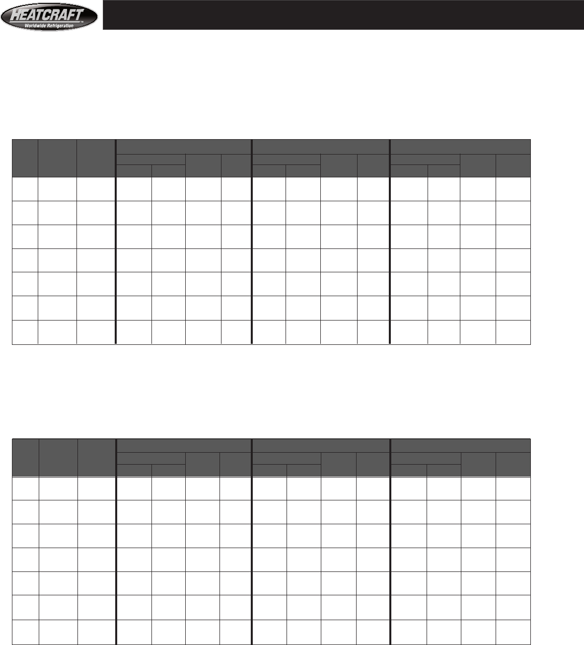
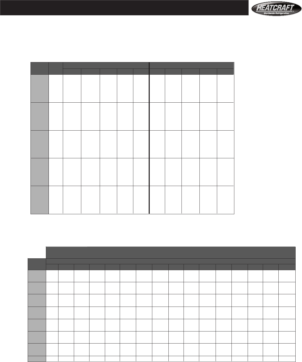
CFM Coil MBH - 4 ROWS MBH - 6 ROWS
Unit Std Face 35°F. SST 40°F. SST 45°F. SST 35°F. SST 40°F. SST 45°F. SST
Size Air Area Total Sens. Total Sens. Total Sens. Total Sens. Total Sens. Total Sens.
03 1500 3.00 61 42 48 36 36 31 74 49 61 43 48 37
06 2845 5.69 110 77 85 66 62 57 143 94 116 82 88 70
08 3750 7.50 152 106 127 93 98 82 187 123 151 107 117 92
10 4690 9.38 189 132 153 116 122 102 236 155 194 136 149 117
12 5844 11.69 242 167 192 143 142 123 291 193 243 170 189 147
14 6875 13.75 288 197 233 173 175 148 334 221 281 198 224 173
18 8750 17.50 367 251 296 221 223 188 442 291 360 251 285 220
20 9625 19.25 394 270 329 245 256 213 486 320 402 281 312 240
26 12750 25.50 531 366 419 313 332 278 641 425 535 374 415 323
34 17000 34.00 708^ 488 559^ 418 442 371 855 567 713^ 498 553 430
41 20188 40.38 840^ 580 664^ 496 525 441 1016 673 846^ 592 657 511
50 24750 49.50 1037^ 706 826^ 615 634^ 532 1242* 820 1036^ 726 811^ 622
65 32292 64.58 1364^ 927 1105^ 814 832^ 704 1641* 1081 1339* 938 1059^ 813
75 37458 74.92 1582^ 1075 1282^ 944 966^ 817 1904* 1254 1553* 1088 1229^ 943
Table 4
Supermarket
Air Conditioning 1/2" tube, entering air at 75°F. DB and 63°F. WB**
1/2" tube, direct expansion, cooling capacities
10 FPI**, large coils, 500 FPM**
CFM Coil MBH - 4 ROWS MBH - 6 ROWS
Unit Std Face 35°F. SST 40°F. SST 45°F. SST 35°F. SST 40°F. SST 45°F. SST
Size Air Area Total Sens. Total Sens. Total Sens. Total Sens. Total Sens. Total Sens.
03 1565 3.13 57 39 44 34 32 29 72 48 60 42 46 36
06 2880 5.76 108 73 88 65 69 56 133 88 111 78 86 67
08 3905 7.81 145 99 121 88 92 76 182 119 151 106 117 91
10 4885 9.77 184 125 149 110 117 97 228 150 187 132 147 115
12 6200 12.40 234 159 192 139 147 121 292 191 238 168 186 144
14 7290 14.58 276 187 227 164 174 145 341 224 284 199 218 171
18 8855 17.71 335 227 276 199 211 176 414^ 273 345 241 267 208
20 10025 20.05 378 254 314 227 240 196 472 312 391 272 302 233
26 13280 26.56 505 342 413 298 320 261 628^ 411 513^ 361 402 311
34 16825 33.65 640^ 434 523^ 378 405 330 796^ 520 649^ 457 510^ 394
41 20365 40.73 775^ 525 633^ 457 490 403 963^^ 630 786^^ 553 617^ 477
50 25313 50.63 962^ 645 793^ 573 603^ 500 1199* 787 984* 984 764^ 593
65 32290 64.58 1312^ 820 1011^ 736 778^ 640 1520* 992 1265* 880 978* 758
75 37675 75.35 1415* 957 1180* 859 908* 747 1773* 1158 1476* 1027 1141* 885
Table 5
Supermarket
Air Conditioning 5/8" tube, entering air at 75°F. DB and 63°F. WB**
5/8 "tube, direct expansion, cooling capacities
10 FPI**, large coils, 500 FPM**
Air Handler Perfromance- Direct Expansion
16
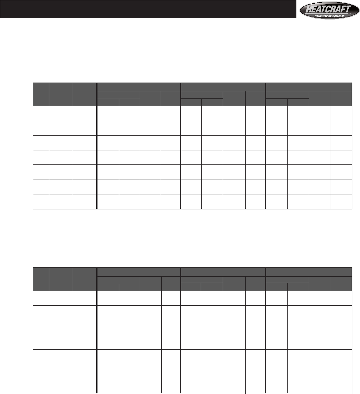
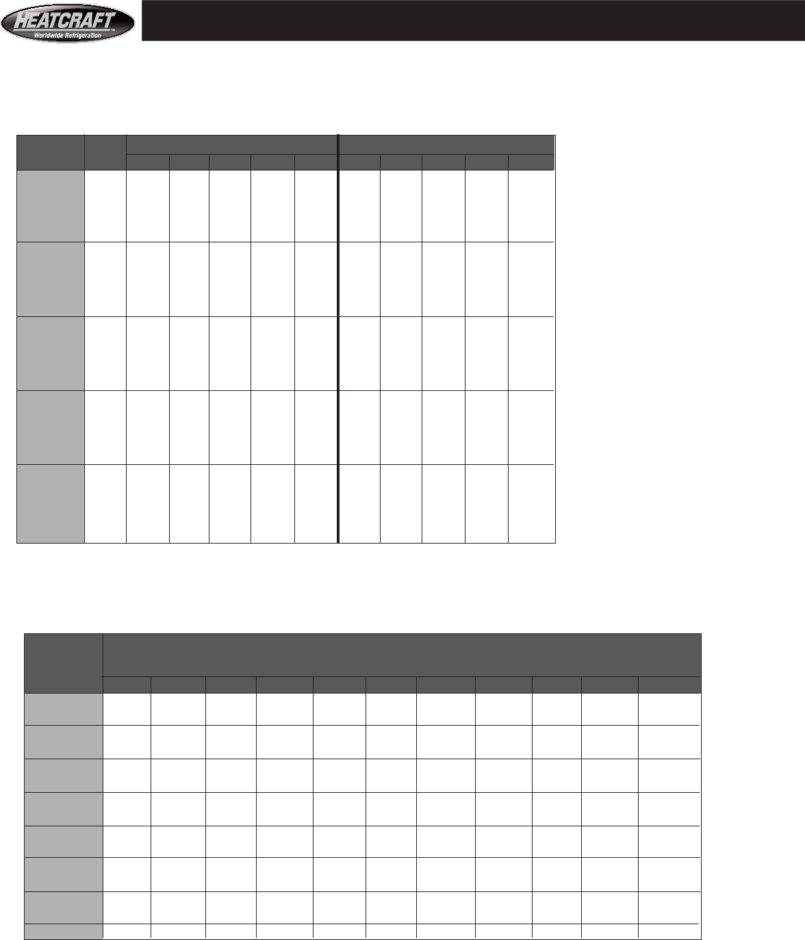
CFM Coil 42°F. Entering Water 44°F. Entering Water 45°F. Entering Water
Unit Std Face MBH MBH MBH
Size Air Area TOTAL SENS GPM PD TOTAL SENS GPM PD TOTAL SENS GPM PD
03 1565 3.13 51 37 10.2 2.4 46 35 9.1 1.9 43 34 8.6 1.7
06 2880 5.76 105 73 20.9 8.8 94 69 18.8 7.2 89 67 17.7 6.5
08 3905 7.81 139 98 27.8 7.6 125 92 25.0 6.3 118 89 23.6 5.6
10 4885 9.77 181 125 36.2 13.6 163 118 32.6 11.2 154 114 30.8 10.1
12 6200 12.40 233 160 46.6 18.2 210 151 41.9 15.0 198 146 39.6 13.5
14 7290 14.58 271 187 54.0 10.6 253 180 50.5 22.8 239 174 47.8 20.6
18 8855 17.71 328 227 65.6 10.8 307 218 61.4 23.8 290 212 58.0 21.5
20 10025 20.05 390 265 77.8 20.2 346 247 69.1 16.4 327 239 65.3 14.8
26 13280 26.56 500 343 99.8 15.6 450 323 89.8 12.8 425 313 84.9 11.6
34 16825 33.65 633 435 126.5 16.5 570 409 113.8 13.6 538 396 107.5 12.2
41 20365 40.73 767 527 153.1 17.0 690 495 137.8 14.0 652 480 130.2 12.6
50 25313 50.63 961^ 658 191.9 17.8 865^ 618 172.8 14.7 817^ 600 163.3 13.3
65 32290 64.58 1105^ 790 220.6 5.5 1125^ 798 224.8 21.7 1064^ 774 212.6 19.6
75 37675 75.35 1289^ 922 257.5 6.0 1313^ 931 262.3 22.6 1241^ 903 248.1 20.4
CFM Coil 42°F. Entering Water 44°F. Entering Water 45°F. Entering Water
Unit Std Face MBH MBH MBH
Size Air Area TOTAL SENS GPM PD TOTAL SENS GPM PD TOTAL SENS GPM PD
03 1500 3.00 62 42 12.5 10.6 57 40 11.5 9.1 54 39 11.5 9.1
06 2845 5.69 125 83 33.5 10.7 113 78 29.5 8.5 109 76 29.5 8.5
08 3750 7.50 163 109 43.5 10.5 148 103 39.5 8.7 142 100 39.5 8.7
10 4690 9.38 203 136 47.5 13.5 179 126 39.5 9.6 172 123 39.5 9.5
12 5854 11.69 257 171 59.5 19.0 228 158 49.5 13.5 219 155 49.5 13.4
14 6875 13.75 296 198 59.5 20.3 269 187 54.5 17.2 259 183 54.5 17.1
18 8750 17.50 377 252 75.5 16.8 342 238 69.5 14.4 330 232 69.5 14.4
20 9625 19.25 414 277 89.5 12.3 374 260 79.5 9.9 360 255 79.5 9.9
26 12750 25.50 558 371 125.5 15.2 499 347 109.5 11.7 480 339 109.5 11.7
34 17000 34.00 751 498 175.5 16.7 680 468 159.5 13.9 655 458 159.5 13.9
41 20190 40.38 880 586 197.5 17.1 799 552 179.5 14.2 766 540 179.5 14.2
50 24750 49.50 1058^ 710 219.5 13.6 983^ 679 219.5 13.5 947^ 663 219.5 13.4
65 32290 64.58 1145^ 917 309.0 12.4 1287^ 888 271.5 18.3 1240^ 867 271.5 18.2
75 37460 74.92 1599^ 1073 379.0 14.6 1482^ 1026 307.5 17.5 1417^ 998 299.5 16.8
GPM = Gallons per minute
PD = Water pressure drop in feet of water ^ These selections have two fluid circuits. All the other
MBH = BTU per Hour in Thousands selections have a single fluid circuit.
Sens. = Sensible Capacity
* To estimate performance of coils at other than 10 FPI or at other air speeds or with other water or air temperatures see page 22,
or call your representative. With your representative, you can have specific computer selected coils rated for your job conditions.
4 Row Coils*
Table 6
Comfort Cooling
1/2" tube, entering air at 80°F. DB and 67°F. WB
1/2" tube, chilled water, cooling capacities
10 FPI*, 4 rows, large coils, 500 FPM*
Table 7 4 Row Coils*
Comfort Cooling
5/8" tube, entering air at 80°F. DB and 67°F. WB
5/8" tube, chilled water, cooling capacities
10 FPI*, large coils, 500 FPM*
Air Handler Performance- Chilled Water
17
GPM = Gallons per minute
PD = Water pressure drop in feet of water ^ These selections have two fluid circuits. All the other
MBH = BTU per Hour in Thousands selections have a single fluid circuit.
Sens. = Sensible Capacity
* To estimate performance of coils at other than 10 FPI or at other air speeds or with other water or air temperatures see page 22,
or call your representative. With your representative, you can have specific computer selected coils rated for your job conditions.
CFM Coil 42°F. Entering Water 44°F. Entering Water 45°F. Entering Water
Unit Std Face MBH MBH MBH
Size Air Area TOTAL SENS GPM PD TOTAL SENS GPM PD TOTAL SENS GPM PD
03 1500 3.00 79 50 15.5 22.6 73 48 15.5 22.4 70 47 15.5 22.3
06 2844 5.69 146 94 29.5 11.9 136 89 29.5 11.8 131 87 29.5 11.7
08 3750 7.50 192 123 39.5 11.6 179 117 39.5 11.5 172 115 39.5 11.5
10 4690 9.38 245 157 49.5 19.3 229 149 49.5 19.2 220 146 49.5 19.1
12 5845 11.69 307 196 59.5 25.0 286 186 59.5 24.8 275 182 59.5 24.7
14 6875 13.75 364 232 79.5 14.3 328 216 69.5 11.1 316 211 69.5 11.1
18 8750 17.50 449 289 89.5 11.9 418 275 89.5 11.8 402 269 89.5 11.8
20 9625 19.25 507 323 99.0 20.2 472 308 99.5 20.3 453 300 99.0 20.0
26 12750 25.50 652 420 139.5 12.0 616 404 123.5 19.1 590 392 119.5 17.9
34 17000 34.00 863 557 179.5 12.6 814 536 159.5 18.1 786 523 159.5 18.0
41 20188 40.38 1033 665 219.5 16.0 978 642 199.5 21.9 945 625 199.5 21.8
50 24750 49.50 1286^ 822 279.5 13.4 1196^ 784 279.5 13.3 1152^ 765 279.5 13.3
65 32291 64.58 1686^ 1078 351.5 19.1 1549^ 1018 331.5 16.9 1491^ 994 332.0 17.0
75 37458 74.92 1922^ 1236 378.0 17.5 1792^ 1179 379.0 17.6 1722^ 1148 378.0 17.4
6 Row Coils*
Table 8
Comfort Cooling
1/2" tube, entering air at 80°F. DB and 67°F. WB
1/2" tube, chilled water, cooling capacities
10 FPI*, 6 rows, large coils, 500 FPM*
CFM Coil 42°F. Entering Water 44°F. Entering Water 45°F. Entering Water
Unit Std Face MBH MBH MBH
Size Air Area TOTAL SENS GPM PD TOTAL SENS GPM PD TOTAL SENS GPM PD
03 1565 3.13 70 47 13.9 5.8 63 44 12.6 4.9 60 43 11.9 4.4
06 2880 5.76 137 90 27.4 20.0 125 84 24.9 16.8 118 82 23.6 15.3
08 3905 7.81 184 121 36.7 17.0 167 114 33.3 14.3 158 110 31.6 13.0
10 4885 9.77 225 149 44.9 8.3 214 145 42.8 25.0 203 140 40.6 22.8
12 6200 12.40 288 190 57.6 11.0 261 179 52.2 9.2 248 173 49.5 8.3
14 7290 14.58 346 227 69.1 16.8 314 213 62.7 14.1 298 206 59.5 12.8
18 8855 17.71 421 276 84.1 17.7 382 259 76.4 14.9 363 251 72.5 13.6
20 10025 20.05 464 306 115.7 23.0 430 292 85.8 13.5 408 283 81.4 12.3
26 13280 26.56 618 407 123.4 14.1 560 383 111.8 11.8 531 371 106.0 10.6
34 16825 33.65 783 516 156.3 15.3 709 485 141.7 12.8 672 470 134.3 11.5
41 20365 40.73 947 625 189.2 16.1 858 588 171.5 13.4 814 568 162.6 12.1
50 25313 50.63 1181^ 781 236.9 15.9 1075^ 735 214.8 13.3 1020^ 711 203.7 12.0
65 32290 64.58 1538^ 1007 307.2 23.2 1325^ 916 264.6 17.6 1325^ 916 264.6 17.6
75 37675 75.35 1795^ 1175 358.4 24.7 1546^ 1068 308.8 18.7 1546^ 1068 308.8 18.7
6 Row Coils*
Table 9
Comfort Cooling
5/8" tube, entering air at 80°F. DB and 67°F. WB
5/8" tube, chilled water, cooling capacities
10 FPI*, 6 rows, large coils, 500 FPM*
Air Handler Perfromance- Chilled Water
18
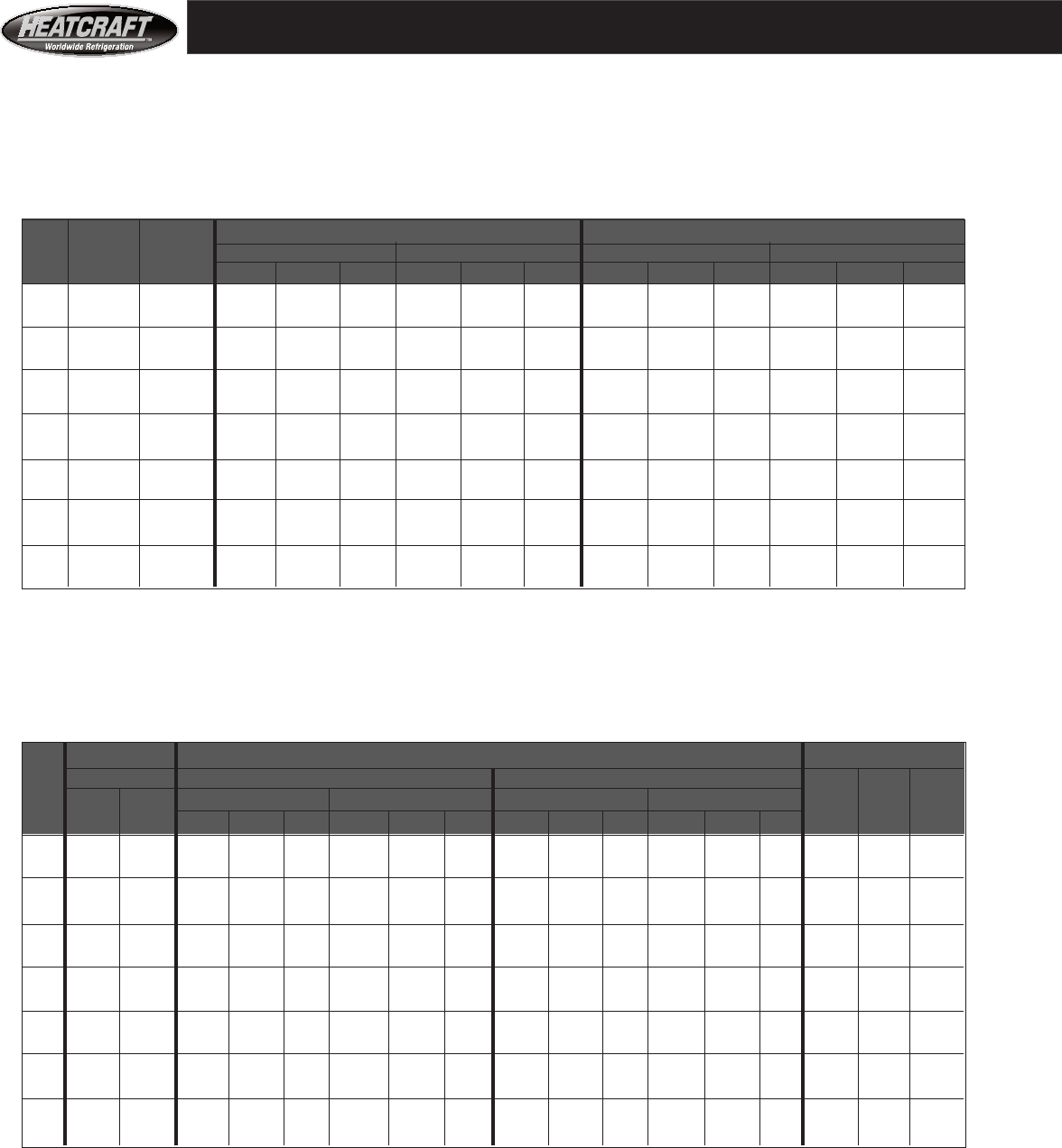
Table 10 Heating 0°F. Air*
Heating,
Water 1/2" tube, entering air at 0°F.
1/2" tube, hot water, heating capacities
10 FPI*, large coils, 500 FPM*
Table 11 Heating 0°F. Air*
Heating,
Water And 5/8" tube, entering air at 0°F.
Steam Type 5**, hot water, heating & steam capacities
10 FPI*, large coils, 500 FPM*
GPM = Gallons per minute ^ These selections have two circuits. All the other selections have a single circuit .
PD = Water pressure drop in feet of water ^^ All steam coils rated at 5 PSIG Steam.
MBH = BTU per Hour in Thousands ** Steam selections for 65 and 75 are two circuits and are 1 inch diameter tube (Type-8).
* To estimate performance of coils at other than 10 FPI or at other air speeds or with other water or air temperatures or other
steam pressures see page 23, or call your representative. With your representative, you can have specific computer selected
coils rated for your job conditions.
Air Handler Performance- Hot Water/Steam
Water Heating Coils Steam Coils^^
CFM Face 180°F. Entering Water 200°F. Entering Water CFM Face One
Unit Std Area One Row Two Row One Row Two Row Std Area Row
Size Air Sq. Ft. MBH GPM PD MBH GPM PD MBH GPM PD MBH GPM PD Air Sq. Ft. MBH
03 1500 3.00 97 10.0 3.9 158 20.5 2.4 110 17.5 1.9 177 20.5 2.4 1375 2.75 126
06 2844 5.69 191 30.5 5.0 304 33.0 5.6 216 33.0 5.6 341 36.0 6.4 2641 5.28 243
08 3750 7.50 252 27.5 15.5 399 43.5 5.9 283 44.0 6.5 452 51.5 7.9 3563 7.13 331
10 4690 9.38 311 41.0 6.1 504 54.5 9.5 359 55.0 10.1 548 61.5 3.2 4454 8.91 409
12 5844 11.69 399 60.5 11.4 625 60.5 10.7 445 60.0 11.0 684 72.0 3.9 4781 9.56 439
14 6875 13.75 466 60.5 11.7 724 80.0 5.0 519 60.0 11.3 812 84.5 5.4 6875 13.75 632
18 8750 17.50 588 71.5 12.4 921 102.0 6.0 661 76.5 13.7 1034 108.0 6.5 8438 16.88 776
20 9625 19.25 643 66.0 13.1 1027 112.0 8.8 718 66.0 12.9 1162 131.0 11.4 9625 19.25 880
26 12750 25.50 835 66.0 14.0 1363 132.0 12.7 932 66.0 13.7 1520 132.0 12.5 12750 25.50 1103
34 17000 34.00 1114 88.0 8.5 1818 176.0 15.7 1242 87.5 8.2 2026 175.0 15.2 16469 32.94 1425
41 20188 40.38 1323 104.5 9.4 2159 209.0 17.8 1475 104.0 9.1 2406 208.0 17.3 19656 39.31 1700
50 24750 49.50 1614^ 121.0 13.4 2635^ 238.5 11.9 1612^ 120.0 13.2 2637^ 240.0 12.0 23625 47.25 1994^
65 32292 64.58 2077^ 135.5 14.9 3409^ 271.0 13.5 2316^ 135.5 14.5 3798^ 269.0 13.1 31000 62.00 2502**
75 37458 74.92 2333^ 133.0 8.5 3952^ 312.0 14.9 2616^ 136.5 8.7 4407^ 313.0 14.6 36167 72.33 2919**
CFM Face 180°F. Entering Water Coils 200°F. Entering Water Coils
Unit Std Area One Row Two Row One Row Two Row
Size Air Sq. Ft. MBH GPM PD MBH GPM PD MBH GPM PD MBH GPM PD
03 1565 3.13 75 7.6 0.3 137 14.1 1.5 85 8.8 0.4 155 16.0 1.8
06 2880 5.76 144 14.8 1.0 259 26.6 4.9 164 16.9 1.3 292 30.1 5.9
08 3905 7.81 194 19.9 1.0 350 35.9 4.6 220 22.8 1.3 394 40.7 5.5
10 4885 9.77 247 25.3 1.8 442 45.3 7.7 280 28.9 2.1 497 51.3 9.2
12 6200 12.40 315 32.3 2.4 562 57.7 10.2 357 36.9 2.9 633 65.3 12.2
14 7290 14.58 375 38.4 3.5 665 68.2 14.9 424 43.7 4.2 747 77.2 17.8
18 8855 17.71 455 46.6 3.8 808 82.8 15.8 514 53.1 4.6 908 93.8 18.8
20 10025 20.05 522 53.5 6.4 899 92.2 4.4 589 60.8 7.7 1013 104.6 5.3
26 13280 26.56 700 71.8 12.4 1205 123.6 8.8 788 81.4 14.9 1355 140.0 10.5
34 16825 33.65 887 90.9 13.4 1526 156.5 9.4 999 103.2 16.1 1717 177.3 11.4
41 20365 40.73 1073 110.1 13.9 1847 189.5 9.9 1209 124.9 16.7 2078 214.6 11.9
50 25312 50.63 1337^ 137.1 13.5 2301^ 236.0 9.8 1505^ 175.5 16.6 2525^ 260.9 11.5
65 32290 64.58 1714^ 175.8 19.7 2949^ 302.4 14.1 1928^ 199.2 23.6 3313^ 342.2 17.0
75 37675 75.35 2000^ 205.1 20.8 3440^ 352.9 14.9 2250^ 232.4 25.0 3865^ 399.3 17.6
19
Water Heating Coils Steam Coils^^
CFM Face 180°F. Entering Water 200°F. Entering Water CFM One Two
Unit Std Area One Row Two Row One Row Two Row Std Row Row
Size Air Sq. Ft. MBH GPM PD MBH GPM PD MBH GPM PD MBH GPM PD Air MBH MBH
03 1500 3.00 65 10.0 3.9 101 10.0 1.8 76 10.0 3.8 119 10.0 1.8 1375 93 148
06 2844 5.69 125 18.5 8.7 195 18.5 4.8 147 19.0 8.9 229 19.0 4.9 2641 179 284
08 3750 7.50 166 25.0 13.0 259 25.0 5.6 195 25.0 12.7 303 25.0 5.4 3750 254 403
10 4690 9.38 200 31.0 3.6 315 31.0 3.4 236 31.5 3.7 370 31.5 3.5 4675 317 499
12 5844 11.69 253 39.0 5.1 396 39.0 4.9 297 39.0 5.0 464 39.0 4.8 5845 395 628
14 6875 13.75 300 45.5 7.0 470 45.5 6.8 353 46.0 6.9 551 46.0 6.8 6875 465 739
18 8750 17.50 382 58.0 8.5 598 58.0 7.9 449 58.5 8.4 701 58.5 7.9 8438 571 907
20 9625 19.25 428 64.0 12.4 666 64.0 12.4 502 64.5 12.3 781 64.5 12.3 9625 651 1035
26 12750 25.50 557 65.5 13.8 864 85.0 5.7 653 66.0 13.7 1013 85.5 5.7 12750 859 1370
34 17000 34.00 743 87.5 8.4 1152 113.0 7.0 871 88.0 8.3 1351 114.0 7.0 17000 1145 1827
41 20188 40.38 882 104.0 9.3 1368 134.5 8.0 1034 104.0 9.1 1605 135.5 8.0 20190 1360 2170
50 24750 49.50 1077^ 120.5 13.2 1683^ 165.0 6.1 1261^ 120.0 12.9 1974^ 166.0 6.1 23625 1586^ 2539
65 32292 64.58 1384^ 134.5 14.6 2207^ 211.0 8.6 1623^ 135.5 14.5 2589^ 213.5 8.6 31000 1848**
75 37458 74.92 1565^ 136.5 8.8 2562^ 246.5 9.6 1837^ 137.5 8.8 3003^ 248.0 9.5 36167 2156**
CFM Face 180°F. Entering Water Coils 200°F. Entering Water Coils
Unit Std Area One Row Two Row One Row Two Row
Size Air Sq. Ft. MBH GPM PD MBH GPM PD MBH GPM PD MBH GPM PD
03 1565 3.13 45 4.6 0.1 86 8.8 0.7 56 5.7 0.2 104 10.7 0.9
06 2880 5.76 89 9.1 0.4 164 16.9 2.2 108 11.2 0.6 197 20.3 3.0
08 3905 7.81 119 12.2 0.4 221 22.7 2.1 146 15.0 0.6 266 27.5 2.8
10 4885 9.77 153 15.7 0.8 281 28.8 3.5 186 19.2 1.0 336 34.7 4.6
12 6200 12.40 196 20.1 1.0 358 36.7 4.6 238 24.6 1.4 428 44.2 6.1
14 7290 14.58 234 24.0 1.5 425 43.6 6.8 283 29.2 2.1 507 52.3 9.0
18 8855 17.71 285 29.2 1.6 516 52.9 7.2 344 35.5 2.2 615 63.6 9.5
20 10025 20.05 329 33.7 2.8 590 60.5 12.6 395 40.8 3.8 703 72.6 16.6
26 13280 26.56 443 45.5 5.5 767 78.7 3.9 531 54.9 7.4 917 94.7 5.2
34 16825 33.65 561 57.6 6.0 972 99.7 4.2 673 69.5 8.0 1162 120.0 5.6
41 20365 40.73 680 69.7 6.2 1177 120.7 4.4 814 84.1 8.3 1406 145.3 5.9
50 25312 50.63 847^ 86.9 6.2 1467^ 150.4 4.4 1015^ 104.9 8.3 1710^ 176.6 5.4
65 32290 64.58 1088^ 111.6 8.9 1884^ 193.2 6.4 1302^ 134.4 11.9 2247^ 232 8.5
75 37675 75.35 1270^ 130.3 9.4 2198^ 225.4 6.7 1519^ 156.9 12.5 2621^ 270.8 8.9
GPM = Gallons per minute ^ These selections have two circuits. All the other selections have a single circuit .
PD = Water pressure drop in feet of water ^^ All steam coils rated at 5 PSIG Steam.
MBH = BTU per Hour in Thousands ** Steam selections for 65 and 75 are two circuits and are 1 inch diameter tube (Type 8).
* To estimate performance of coils at other than 10 FPI or at other air speeds or with other water or air temperatures or
other steam pressures see page 23, or call your representative. With your representative, you can have specific computer
selected coils rated for your job conditions.
Table 13 Heating 60°F. Air*
Heating,
Water And 5/8" tube, entering air at 60°F.
Steam Type 5**, hot water, heating & steam capacities
10 FPI*, large coils, 500 FPM*
Table 12 Heating 60°F. Air*
Heating,
Water 1/2" tube, entering air at 60°F.
1/2" tube, hot water, heating capacities
10 FPI, large coils, 500 FPM
Air Handler Performance- Hot Water/Steam
20
Heat Reclaim Coil Selection Example:
Select reclaim coil for Size 26 air handler at 13280 CFM,
344 MBH reclaimed at 45°F. Temperature Difference.
A. Change the application’s requirement at application’s TD
to adjusted requirement at 50°F. TD. Use Table 15:
344/0.9 = 382.2 MBH (adjusted)
B. Divide the adjusted MBH by the coil face area:
382.2 / 26.56 = 14.4 MBH (adjusted) per square foot
C. Find the coil air speed:
13280 / 26.56 = 500 fpm
D. Select coil rows and fins per inch from Table 16 at coil air
speed and with enough MBH to meet the MBH (adjusted to 50°F. TD) per square foot figured in step B:
Select 3 row 8 fin per inch coil with capacity of 14.56 MBH per square foot at 50°F. TD.
For this application, capacity equals: (14.56 x 26.56 x 0.9) or 348 MBH for size 26 at 45°F. TD.
E. When ordering, please specify refrigerant type and the total heat of rejection for each reclaim circuit.
Or specify the per cent of the total heat of rejection that is reclaimed for each circuit.
Table 15 Heat reclaim correction factor for temperature difference between air and refrigerant.
Temperature Difference 20 25 30 35 40 45 50 60
Correction Factor 0.4 0.5 0.6 0.7 0.8 0.9 1.0 1.2
This table for R-22, for R404A & R507, multiply MBH by 0.98
For heat reclaim capacities at other temperature differences, multiply by factor in Table 15.
Table 16
Refrigeration Gas
Heat Reclaim 1/2" and 5/8" tube, 50°F TD, entering air to condensing temperatire
Type A and Type 5, hot gas reclaim, heating capacities
MBH per SQ FT of coil face area
FPM, Type A Coils (1/2" DIA.) FPM, Type 5 Coils (5/8" DIA.)
Rows FPI 400 450 500 550 600 400 450 500 550 600
6 7.70 8.18 9.43 9.90 10.25 9.25 9.85 10.41 10.91 11.41
8 8.90 9.45 10.90 11.38 11.85 10.04 10.70 11.33 11.92 12.47
2 10 10.40 11.05 12.15 12.73 13.18 11.12 11.93 12.68 13.37 14.03
12 11.70 12.45 13.13 13.77 14.35 12.20 13.13 13.99 14.80 15.56
14 12.88 13.73 14.48 15.18 15.83 13.23 14.28 15.26 16.18 17.04
6 11.08 11.96 12.88 13.50 13.98 12.27 13.13 13.98 14.77 15.52
8 12.60 13.60 14.56 15.25 15.90 13.17 14.13 15.07 15.96 16.79
3 10 13.93 14.95 15.93 16.80 17.63 14.30 15.48 16.58 17.61 18.58
12 14.91 16.02 17.08 18.03 18.95 15.40 16.73 17.98 19.16 20.28
14 16.08 17.30 18.50 19.55 20.58 16.39 17.87 19.28 20.60 21.86
6 13.27 14.35 15.53 16.38 17.18 14.50 15.66 16.77 17.81 18.79
8 14.98 16.21 17.43 18.47 19.47 15.39 16.66 17.89 19.04 20.12
4 10 16.20 17.48 18.75 19.92 21.07 16.50 17.96 19.36 20.68 21.94
12 17.47 18.73 19.98 21.25 22.50 17.48 19.11 20.68 22.17 23.58
14 18.57 19.95 21.30 22.65 23.97 18.32 20.11 21.83 23.48 25.05
6 16.41 17.83 19.58 20.78 21.90 17.38 19.10 20.62 22.09 23.49
8 18.35 19.93 21.50 23.10 24.67 18.10 19.96 21.61 23.21 24.74
6 10 19.13 20.90 22.63 24.20 25.75 18.96 21.00 22.83 24.62 26.33
12 19.80 21.70 23.58 25.23 26.87 19.65 21.83 23.82 25.78 27.67
14 19.87 22.01 24.02 26.02 27.95 20.18 22.48 24.61 26.72 28.75
6 18.25 20.08 21.75 23.45 25.08 18.93 21.51 23.02 24.69 26.42
8 19.29 21.31 23.16 25.04 26.86 19.49 21.82 23.82 25.60 27.47
8 10 20.04 22.23 24.24 26.30 28.28 20.11 22.57 24.74 26.67 28.71
12 20.51 22.82 24.95 27.14 29.26 20.58 23.12 25.43 27.63 29.68
14 20.82 23.22 25.44 27.72 29.95 20.91 23.51 25.93 28.25 30.45
Table 14
Coil Perfromance- Heat Reclaim MBH/SQ FT
Air Handler Type A Large Type 5 Large
Unit Coil Face Area Coil Face Area
Size Square Feet Square Feet
03 3.13 3.00
06 5.76 5.69
08 7.81 7.50
10 9.77 9.38
12 12.40 11.69
14 14.58 13.75
18 17.71 17.50
20 20.05 19.25
26 26.56 25.50
34 33.65 34.00
41 40.73 40.38
50 50.63 49.50
65 64.58 64.58
75 75.35 74.92
21
ENT AIR
Table 18:
Capacity Correction Factors* To Coil Performance
Of 67°F Wb And 40°F Evaporating
Ent Air WB Refrigerant Evaporating Temperature °F.
Temp. °F. 35 36 37 38 39 40 41 42 43 44 45 46 47 48 49 50
60 0.820 0.794 0.768 0.740 0.713 0.685 0.656 0.628 0.598 0.568 0.538 0.506 0.475 0.442 0.409 0.376
61 0.862 0.837 0.810 0.783 0.756 0.727 0.698 0.670 0.640 0.610 0.580 0.548 0.517 0.484 0.452 0.418
62 0.907 0.881 0.854 0.827 0.799 0.771 0.743 0.714 0.684 0.654 0.623 0.592 0.561 0.528 0.496 0.462
63 0.950 0.923 0.897 0.870 0.842 0.814 0.785 0.756 0.727 0.696 0.666 0.635 0.603 0.571 0.538 0.505
64 0.994 0.969 0.942 0.914 0.887 0.859 0.831 0.802 0.772 0.742 0.712 0.680 0.649 0.616 0.583 0.550
65 1.040 1.014 0.988 0.960 0.933 0.905 0.876 0.847 0.818 0.788 0.757 0.726 0.694 0.662 0.629 0.596
66 1.087 1.061 1.035 1.008 0.980 0.952 0.923 0.894 0.864 0.835 0.804 0.773 0.741 0.709 0.676 0.642
67 1.136 1.109 1.083 1.055 1.028 1.000 0.971 0.943 0.913 0.883 0.852 0.822 0.789 0.757 0.724 0.691
68 1.185 1.158 1.132 1.105 1.077 1.050 1.020 0.992 0.962 0.932 0.901 0.870 0.838 0.806 0.773 0.740
69 1.235 1.209 1.182 1.155 1.127 1.100 1.071 1.042 1.012 0.982 0.952 0.920 0.889 0.856 0.824 0.790
70 1.286 1.260 1.235 1.206 1.179 1.152 1.122 1.094 1.063 1.033 1.003 0.972 0.940 0.908 0.875 0.841
71 1.339 1.313 1.285 1.260 1.231 1.203 1.175 1.146 1.115 1.086 1.055 1.024 0.993 0.960 0.927 0.894
72 1.393 1.365 1.340 1.314 1.285 1.257 1.229 1.200 1.170 1.140 1.110 1.079 1.046 1.015 0.981 0.948
73 1.450 1.422 1.395 1.369 1.340 1.313 1.285 1.255 1.225 1.195 1.165 1.134 1.103 1.070 1.036 1.003
74 1.505 1.479 1.451 1.425 1.396 1.370 1.340 1.310 1.281 1.252 1.221 1.190 1.159 1.126 1.094 1.060
* Note: correction factor = (enthalpy of air temperature - enthalpy of evaporator temperature) in BTU/LB divided by 16.39
Coil Performance- Direct Expansion MBH/SQ FT
Table 17
Wet Evaporator
Capacity
1/2" and 5/8" tube, entering air 80°F. DB, 67°F. WB
Type A and Type 5, direct expansion at 40ºF. evaporating, cooling capacities
MBH per SQ FT of coil face area
FPM, Type A Coils (1/2" DIA.) FPM, Type 5 Coils (5/8" DIA.)
Rows FPI 400 450 500 550 600 400 450 500 550 600
6 11.3 12.1 12.8 13.4 14.0 13.1 13.8 14.5 15.2 15.8
8 13.0 13.9 14.7 15.4 16.1 14.9 15.8 16.6 17.4 18.1
3 10 14.4 15.3 16.2 17.0 17.8 16.2 17.2 18.2 19.0 19.8
12 15.4 16.5 17.4 18.3 19.1 17.3 18.4 19.4 20.3 21.2
14 16.3 17.4 18.4 19.3 20.2 18.0 19.2 20.4 21.4 22.4
6 14.0 15.0 16.0 16.9 17.7 15.8 16.8 17.8 18.7 19.5
8 15.9 17.1 18.2 19.2 20.1 17.7 18.9 20.0 21.0 22.0
4 10 17.4 18.7 19.8 20.9 22.0 19.0 20.4 21.7 22.8 23.9
12 18.5 19.9 21.2 22.3 23.4 19.9 21.4 22.8 24.1 25.3
14 19.4 20.9 22.2 23.5 24.6 20.7 22.3 23.8 25.2 26.5
6 15.9 17.1 18.3 19.3 20.3 17.9 19.2 20.5 21.6 22.6
8 18.3 19.7 21.1 22.3 23.5 19.8 21.3 22.7 24.0 25.2
5 10 19.8 21.3 22.8 24.2 25.5 21.0 22.7 24.3 25.7 27.1
12 20.9 22.6 24.2 25.6 27.0 21.8 23.6 25.4 27.0 28.5
14 21.8 23.6 25.3 26.8 28.3 22.5 24.4 26.3 28.0 29.6
6 17.8 19.2 20.5 21.7 22.8 19.7 21.2 22.7 24.0 25.3
8 19.7 21.3 22.7 24.1 25.4 21.4 23.1 24.8 26.3 27.8
6 10 21.1 22.8 24.4 25.9 27.2 22.5 24.4 26.3 28.0 29.7
12 22.1 23.9 25.6 27.2 28.7 23.3 25.3 27.3 29.2 31.0
14 22.9 24.8 26.6 28.2 29.8 23.9 26.0 28.1 30.1 32.0
6 20.9 22.7 24.3 25.9 27.4 22.3 24.2 26.0 27.7 29.4
8 22.7 24.7 26.6 28.4 30.0 23.8 25.9 28.0 29.9 31.7
8 10 23.9 26.1 28.1 30.1 31.9 24.6 27.0 29.3 31.3 33.3
12 24.8 27.1 29.3 31.3 33.2 25.2 27.7 30.1 32.4 34.6
14 25.4 27.8 30.1 32.2 34.2 25.7 28.2 30.7 33.1 35.4
Actual capacity will vary
with coil circuiting
Note: Please contact your representative for ARI ratings for coils. These tables are only estimates.
For extimates for other web bulb and evaporator temperatures, multiply by correction
factors in Table 18.
22
* Note: correction factor = (enthalpy of air temperature - enthalpy of water temperature) in BTU /LB divided by 13.97.
Capacity Correction Factors* To Coil Performance
Of 67°F. Wb Air And 45 Entering Water
Ent Air WB Entering Water Temperature °F.
TEMP. °F. 40 41 42 43 44 45 46 47 48 49 50
60 0.805 0.782 0.736 0.702 0.666 0.630 0.594 0.556 0.518 0.480 0.440
61 0.853 0.819 0.785 0.750 0.715 0.680 0.643 0.606 0.568 0.529 0.490
62 0.903 0.869 0.836 0.801 0.765 0.730 0.693 0.656 0.618 0.579 0.540
63 0.954 0.921 0.887 0.852 0.817 0.781 0.745 0.707 0.670 0.631 0.591
64 1.007 0.974 0.940 0.905 0.870 0.834 0.798 0.760 0.722 0.684 0.644
65 1.062 1.028 0.994 0.959 0.924 0.888 0.852 0.815 0.777 0.738 0.699
66 1.117 1.083 1.049 1.014 0.979 0.943 0.907 0.870 0.832 0.793 0.754
67 1.173 1.140 1.106 1.071 1.036 1.000 0.963 0.926 0.888 0.850 0.810
68 1.230 1.197 1.163 1.128 1.093 1.057 1.021 0.984 0.946 0.907 0.868
69 1.290 1.256 1.223 1.188 1.152 1.117 1.080 1.043 1.005 0.966 0.927
70 1.350 1.316 1.283 1.248 1.213 1.177 1.140 1.103 1.065 1.026 0.987
71 1.412 1.378 1.344 1.309 1.274 1.238 1.202 1.165 1.127 1.088 1.049
72 1.475 1.441 1.407 1.372 1.337 1.301 1.265 1.228 1.190 1.151 1.112
73 1.540 1.506 1.472 1.437 1.402 1.366 1.330 1.293 1.255 1.216 1.177
74 1.606 1.572 1.538 1.503 1.468 1.432 1.396 1.359 1.321 1.282 1.243
Coil Perfromance- Chilled Water MBH/SQ FT
1/2" and 5/8" tube, entering air 80°F. DB, 67°F. WB
Type A and Type 5, chilled water at 45°F., cooling capacities
MBH per SQ FT of coil face area (Max. water veocity= 3 fps)
Note: Please contact your representative for ARI ratings for coils. These tables are only estimates.
For estimates for other wet bulb and water temperatures, multiply by correction factor in
Table 20.
Actual capacity will vary
with coil circuiting
and flow rate
Table 19
Chilled
Water
FPM, Type A Coils (1/2" DIA.) FPM, Type 5 Coils (5/8" DIA.)
Rows FPI 400 450 500 550 600 400 450 500 550 600
6 7.3 7.9 8.3 8.8 9.2 10.3 11.2 12.0 12.4 12.9
8 8.7 9.3 9.9 10.5 11.0 11.5 12.5 13.5 14.0 14.5
3 10 9.8 10.6 11.3 12.0 12.6 12.5 13.7 14.7 15.2 15.8
12 10.9 11.7 12.5 13.2 14.0 13.3 14.5 15.6 16.2 16.8
14 11.7 12.7 13.6 14.4 15.2 13.9 15.2 16.4 17.0 17.6
6 9.1 9.8 10.4 11.0 11.6 12.3 13.4 13.7 14.8 15.7
8 10.6 11.4 12.2 12.9 13.6 13.6 14.9 15.3 16.4 17.5
4 10 11.8 12.8 13.7 14.6 15.4 15.4 16.1 17.5 18.7 19.4
12 12.9 14.0 15.0 16.0 16.9 16.2 16.9 18.5 19.9 20.6
14 13.8 15.0 16.1 17.2 18.2 16.9 17.7 19.3 20.7 21.5 .
6 11.7 12.6 13.5 14.3 15.1 14.6 15.6 16.4 17.1 17.8
8 13.4 14.6 15.6 16.6 17.2 16.1 17.2 18.1 18.9 19.7
5 10 14.8 16.1 17.0 17.7 18.5 17.2 18.4 19.4 20.2 21.1
12 15.9 17.0 17.9 18.7 19.6 17.5 19.3 20.4 21.4 22.2
14 16.8 17.8 18.7 19.5 20.4 18.2 20.0 21.1 22.2 23.1
6 13.1 14.1 15.2 16.1 17.1 15.9 17.3 17.8 19.1 20.3
8 14.8 16.1 17.3 18.5 19.6 17.3 19.0 19.4 20.9 22.3
6 10 16.2 17.6 19.0 20.1 20.9 18.3 20.2 20.6 22.2 23.8
12 17.2 18.9 20.2 21.2 22.0 19.1 21.1 21.5 23.2 24.9
14 18.1 19.9 21.0 22.0 22.9 19.8 21.9 22.5 24.4 26.2
6 16.0 17.4 19.0 20.0 20.8 18.3 20.1 20.6 21.7 22.6
8 17.7 19.4 20.6 21.7 22.6 19.6 21.6 22.3 23.4 24.5
8 10 19.0 20.5 21.8 23.0 23.9 20.5 22.7 23.4 24.7 25.9
12 19.9 21.4 22.7 23.9 25.0 21.4 23.7 24.3 25.7 26.9
14 20.4 22.0 23.4 24.7 25.8 21.8 24.2 24.9 26.3 27.7
Table 20
23
FPM, Type A Coils (1/2" DIA.) FPM, Type 5 Coils (5/8" DIA.)
Rows FPI 400 500 600 650 700 400 500 600 650 700
6 11.2 12.7 14.0 14.6 15.2 15.1 17.0 18.5 19.3 20.0
8 14.2 16.0 17.6 18.3 19.0 18.8 20.9 22.8 23.7 24.5
1 10 17.1 19.2 21.0 21.9 22.7 21.9 24.4 26.6 27.5 28.4
12 19.9 22.3 24.4 25.3 26.2 24.6 27.4 29.9 30.9 31.9
14 22.7 25.4 27.6 28.6 29.6 26.9 30.1 32.7 33.8 34.9
6 20.3 23.3 25.9 27.1 28.3 25.8 29.5 32.6 34.0 35.4
8 25.0 28.6 31.8 33.3 34.7 30.8 35.0 38.8 40.4 42.1
2 10 29.4 33.6 37.3 39.0 40.6 34.7 39.6 43.9 45.8 47.6
12 33.5 38.3 42.5 44.4 46.2 37.8 43.4 48.1 50.3 52.3
14 37.3 42.6 47.3 49.4 51.4 40.4 46.5 51.7 54.2 56.3
6 27.8 32.1 36.0 37.8 39.6 35.2 40.8 45.6 47.9 50.1
8 33.5 38.8 43.5 45.7 47.8 40.1 46.9 52.9 55.7 58.3
3 10 38.4 44.7 50.2 52.7 55.2 43.9 51.6 58.6 61.7 64.8
12 42.8 49.9 56.3 59.2 61.9 46.7 55.3 63.0 66.5 70.0
14 46.7 54.7 61.8 65.0 68.1 48.9 58.2 66.5 70.4 74.1
FPM, Type 5 Coils (5/8" DIA.) FPM, Type 8 Coils (1" DIA.)
Rows FPI 400 500 600 650 700 400 500 600 650 700
6 27.4 31.0 34.0 35.4 36.6 23.7 26.7 29.2 30.4 31.5
8 34.3 38.2 41.2 42.4 43.5 30.3 34.0 37.1 38.4 39.7
1 10 39.6 43.2 45.5 46.2 46.7 36.2 40.3 43.7 45.1 46.4
12 43.3 46.1 47.0 56.6 57.9 42.3 46.3 49.2 50.4 51.4
14 45.6 47.0 58.7 59.9 60.8 46.3 50.2 52.9 53.9 54.8
6 49.4 56.6 62.8 65.6 68.3
8 56.9 65.4 72.6 75.7 78.4
2 10 62.8 72.3 79.7 82.7 85.3
12 67.5 77.5 84.8 87.5 89.8
14 71.3 81.4 88.3 90.7 92.4
Ent Air Average Water Temperature^, °F. Steam Pressure, PSIG
Temp. °F. 120 130 140 150 160 170 180 190 5 10 20 25 30 40 50
-20 1.077 1.154 1.231 1.308 1.385 1.462 1.538 1.615 1.088 1.142 1.228 1.263 1.295 1.351 1.395
-10 1.000 1.077 1.154 1.231 1.308 1.385 1.462 1.538 1.044 1.098 1.184 1.219 1.251 1.306 1.351
0 0.923 1.000 1.077 1.154 1.231 1.308 1.385 1.462 1.000 1.054 1.140 1.175 1.207 1.262 1.306
10 0.846 0.923 1.000 1.077 1.154 1.231 1.308 1.385 0.956 1.010 1.096 1.131 1.162 1.218 1.262
20 0.769 0.846 0.923 1.000 1.077 1.154 1.231 1.308 0.912 0.966 1.052 1.087 1.118 1.174 1.218
30 0.692 0.769 0.846 0.923 1.000 1.077 1.154 1.231 0.868 0.922 1.007 1.043 1.074 1.130 1.174
40 0.615 0.692 0.769 0.846 0.923 1.000 1.077 1.154 0.824 0.878 0.963 0.999 1.030 1.086 1.130
50 0.538 0.615 0.692 0.769 0.846 0.923 1.000 1.077 0.780 0.834 0.919 0.955 0.986 1.042 1.086
60 0.462 0.538 0.615 0.692 0.769 0.846 0.923 1.000 0.736 0.790 0.875 0.911 0.942 0.998 1.042
70 0.385 0.462 0.538 0.615 0.692 0.769 0.846 0.923 0.692 0.746 0.831 0.867 0.898 0.954 0.998
80 0.308 0.385 0.462 0.538 0.615 0.692 0.769 0.846 0.648 0.702 0.787 0.823 0.854 0.910 0.954
90 0.231 0.308 0.385 0.462 0.538 0.615 0.692 0.769 0.604 0.658 0.743 0.779 0.810 0.866 0.910
100 0.154 0.231 0.308 0.385 0.462 0.538 0.615 0.692 0.560 0.614 0.699 0.734 0.766 0.822 0.866
^ Average water temperature = (entering water temp + leaving water temp) divided by 2.
** For type 5, at 5 PSIG, if (total MBH divided by 0.961) divided by coil tubes is more than to 50 LB per tube, the condensate loading may be too high. At
higher pressures the condensate loading can be more than 50 LB per tube. Get a computer rating for the application.
Table 21
Hot Water
1/2" and 5/8" tube, entering air 60°F. DB
Type A and Type 5, 190°F. average water temperature^, heating capacities
MBH per SQ FT of coil face area (water velocity=3 fps).
Actual capacity will vary
with coil circuiting and
flow rate
To estimate for other entering air and average water temperatures, multiply by correction factor in
Table 23.
Table 22
Steam
5/8" and 1" tube, entering air 0°F. DB
Type 5*** and Type 8, 190°F. steam at 5 PSIG, heating capacities
MBH per SQ FT of coil face area
Note: Please contact your representative for ARI ratings for coils. These tables are only estimates.
To estimate for other entering air and steam pressures multiply by correction factor in Table 23.
*Type 8 coils offered as one row
only on model 65 and 75.
Table 23
Capacity connections Factors to Table 21 for other than 60°F. and 190 average water temperature^
Capcity Correction Facors to Table 22 for other than 0°F. air and 5 PSIG steam***.
Coil Performance- Heating, Water & Steam
24
Fan Performance
Size 03
9" Forward Curved Fan
CFM Coil Total Static Pressure - Inches Of Water
Std. Vel. 0.50 1.00 1.25 1.50 1.75 2.00 2.25 2.50
Air FPM RPM BHP RPM BHP RPM BHP RPM BHP RPM BHP RPM BHP RPM BHP RPM BHP
1200 383 848 0.23 1141 0.40 1273 0.50 1403 0.62 1530 0.75 1643 0.87 1747 0.99 1843 1.12
1300 415 862 0.26 1149 0.44 1274 0.54 1395 0.65 1515 0.78 1633 0.92 1741 1.50 1840 1.19
1400 447 877 0.29 1159 0.49 1280 0.59 1395 0.70 1507 0.82 1618 0.96 1729 1.11 1832 1.25
1500 479 892 0.33 1172 0.54 1289 0.64 1399 0.76 1506 0.88 1611 1.01 1714 1.15 1819 1.31
1600 511 910 0.37 1185 0.59 1300 0.70 1408 0.82 1510 0.94 1610 1.07 1708 1.21 1805 1.36
1700 543 930 0.41 1119 0.64 1313 0.76 1418 0.89 1518 1.01 1614 1.14 1708 1.28 1800 1.42
1800 575 951 0.47 1214 0.70 1327 0.83 1430 0.96 1528 1.09 1621 1.22 1712 1.36 1800 1.50
1900 607 973 0.52 1229 0.76 1341 0.90 1443 1.03 1539 1.17 1631 1.31 1719 1.45 1804 1.59
2000 639 998 0.59 1243 0.83 1355 0.97 1457 1.11 1552 1.25 1642 1.40 1728 1.54 1811 1.69
2100 671 1024 0.66 1258 0.91 1370 1.05 1472 1.19 1566 1.34 1654 1.49 1739 1.65 1821 1.80
2200 703 1052 0.73 1276 0.99 1385 1.13 1486 1.28 1580 1.44 1668 1.59 1751 1.75 1831 1.91
2300 735 1081 0.82 1295 1.07 1399 1.22 1501 1.37 1594 1.54 1681 1.70 1764 1.86 1843 2.03
2400 767 1111 0.91 1314 1.17 1416 1.32 1515 1.47 1609 1.64 1696 1.81 1778 1.98 1856 2.15
2500 799 1142 1.01 1335 1.27 1434 1.42 1530 1.58 1623 1.75 1710 1.93 1792 2.10 1870 2.28
2600 831 1174 1.11 1357 1.38 1453 1.53 1546 1.70 1638 1.86 1725 2.05 1806 2.23 1884 2.42
2700 863 1208 1.23 1380 1.49 1473 1.65 1564 1.82 1653 1.99 1740 2.17 1821 2.36 1898 2.15
Size 03
9" Forward Curved Fan
CFM Coil Total Static Pressure - Inches Of Water
Std. Vel. 2.50 3.00 3.50 4.00 4.50 5.00 5.50 6.00
Air FPM RPM BHP RPM BHP RPM BHP RPM BHP RPM BHP RPM BHP RPM BHP RPM BHP
1200 383 1843 1.12 2020 1.38 2179 1.65 2327 1.94 2464 2.24 2594 2.55 2716 2.87 2833 3.21
1300 415 1840 1.19 2020 1.46 2182 1.74 2330 2.04 2469 2.34 2600 2.66 2723 2.99 2840 3.33
1400 447 1832 1.25 2017 1.54 2181 1.83 2332 2.14 2472 2.45 2604 2.78 2728 3.12 2846 3.46
1500 479 1819 1.31 2010 1.62 2179 1.93 2332 2.24 2474 2.57 2607 2.90 2732 3.25 2851 3.60
1600 511 1805 1.36 1999 1.69 2173 2.02 2329 2.35 2473 2.69 2608 3.03 2734 3.39 2855 3.75
1700 543 1800 1.42 1983 1.75 2163 2.11 2324 2.46 2471 2.81 2607 3.17 2735 3.53 2856 3.90
1800 575 1800 1.50 1974 1.82 2147 2.18 2315 2.56 2465 2.93 2604 3.30 2734 3.68 2857 4.06
1900 607 1804 1.59 1972 1.90 2136 2.25 2300 2.65 2456 3.05 2598 3.44 2731 3.83 2855 4.23
2000 639 1811 1.69 1973 2.00 2130 2.34
2100 671 1821 1.80 1978 2.12 2130 2.45
2200 703 1831 1.91 1985 2.24 2133 2.58
2300 735 1843 2.03 1994 2.36 2138 2.71
2400 767 1856 2.15 2005 2.50 2146 2.85
2500 799 1870 2.28 2017 2.64 2156 3.00
2600 831 1884 2.42 2030 2.79 2167 3.16
2700 863 1898 2.55 2043 2.94 2179 3.33
Maximum ODP Motor Frame Size for Models 03 — 182 T
Size 06
12" Forward Curved Fan
CFM Coil Total Static Pressure - Inches Of Water
Std. Vel. 0.50 1.00 1.25 1.50 1.75 2.00 2.25 2.50
Air FPM RPM BHP RPM BHP RPM BHP RPM BHP RPM BHP RPM BHP RPM BHP RPM BHP
2200 382 624 0.39 832 0.62 925 0.76 1015 0.92 1105 1.10 1207 1.32 1291 1.52 1366 1.72
2400 417 637 0.46 841 0.70 929 0.84 1013 1.00 1095 1.17 1178 1.36 1272 1.59 1355 1.82
2600 451 651 0.54 852 0.80 937 0.93 1017 1.09 1094 1.26 1170 1.45 1246 1.65 1329 1.88
2800 486 666 0.63 864 0.91 946 1.05 1024 1.20 1098 1.37 1170 1.55 1241 1.75 1311 1.96
3000 521 683 0.72 876 1.03 958 1.17 1033 1.33 1105 1.50 1174 1.68 1241 1.87 1307 2.08
3200 556 702 0.83 888 1.17 970 1.32 1044 1.47 1114 1.64 1181 1.82 1246 2.01 1309 2.22
3400 590 723 0.96 901 1.32 982 1.48 1056 1.64 1125 1.81 1190 1.99 1253 2.18 1314 2.38
3600 625 746 1.09 916 1.48 995 1.65 1068 1.82 1136 1.99 1201 2.17 1262 2.36 1321 2.57
3800 660 770 1.25 930 1.64 1007 1.84 1081 2.02 1148 2.20 1212 2.38 1272 2.57 1331 2.78
4000 694 796 1.42 945 1.81 1022 2.04 1093 2.23 1161 2.42 1224 2.61 1284 2.80 1341 3.01
4200 729 823 1.60 963 2.00 1036 2.24 1106 2.46 1173 2.66 1236 2.86 1296 3.05 1352 3.26
4400 764 850 1.81 981 2.21 1051 2.45 1121 2.71 1186 2.92 1249 3.12 1308 3.33 1364 3.54
4600 799 879 2.03 1001 2.44 1068 2.68 1135 2.94 1198 3.19 1261 3.41 1320 3.62 1376 3.84
4800 833 907 2.27 1022 2.69 1086 2.93 1150 3.20 1214 3.47 1274 3.71 1333 3.94 1389 4.16
5000 868 937 2.54 1045 2.96 1105 3.21 1166 3.47 1228 3.75 1286 4.03 1345 4.27 1401 4.50
SIZE 06
12" Forward Curved Fan
CFM Coil Total Static Pressure - Inches Of Water
Std. Vel. 2.50 3.00 3.50 4.00 4.50 5.00 5.50 6.00
Air FPM RPM BHP RPM BHP RPM BHP RPM BHP RPM BHP RPM BHP RPM BHP RPM BHP
2200 382 1366 1.72 1498 2.12 1617 2.51 1725 2.91 1827 3.32 1922 3.73 2012 4.15
2400 417 1355 1.82 1496 2.26 1618 2.69 1729 3.01 1832 3.55 1928 3.99 2019 4.43
2600 451 1329 1.88 1487 2.38 1616 2.85 1730 3.32 1835 3.78 1932 4.25 2024 4.72
2800 486 1311 1.96 1464 2.46 1607 2.99 1727 3.50 1835 4.00 1934 4.50 2027 5.01
3000 521 1307 2.08 1439 2.53 1586 3.09 1717 3.66 1831 4.21 1934 4.75
3200 556 1309 2.22 1433 2.67 1557 3.16 1696 3.77 1820 4.38 1928 4.97
3400 590 1314 2.38 1433 2.82 1549 3.31 1665 3.84 1798 4.50
3600 625 1321 2.57 1436 3.01 1547 3.49 1657 4.02 1767 4.58
3800 660 1331 2.78 1442 3.23 1549 3.69
4000 694 1341 3.01 1450 3.44 1554 3.92
4200 729 1352 3.26 1459 3.70 1561 4.17
4400 764 1364 3.54 1470 3.98 1570 4.45
4600 799 1376 3.84 1481 4.29
4800 833 1389 4.16 1493 4.62
5000 868 1401 4.50
Maximum ODP Motor Frame Size for Models 06 — 184 T Medium Pressure Fan Must Be Used
Coil Face Velocity is for a Large Cooling Coil, Type A (1/2" Tube Diameter) When Operating in Shaded Area
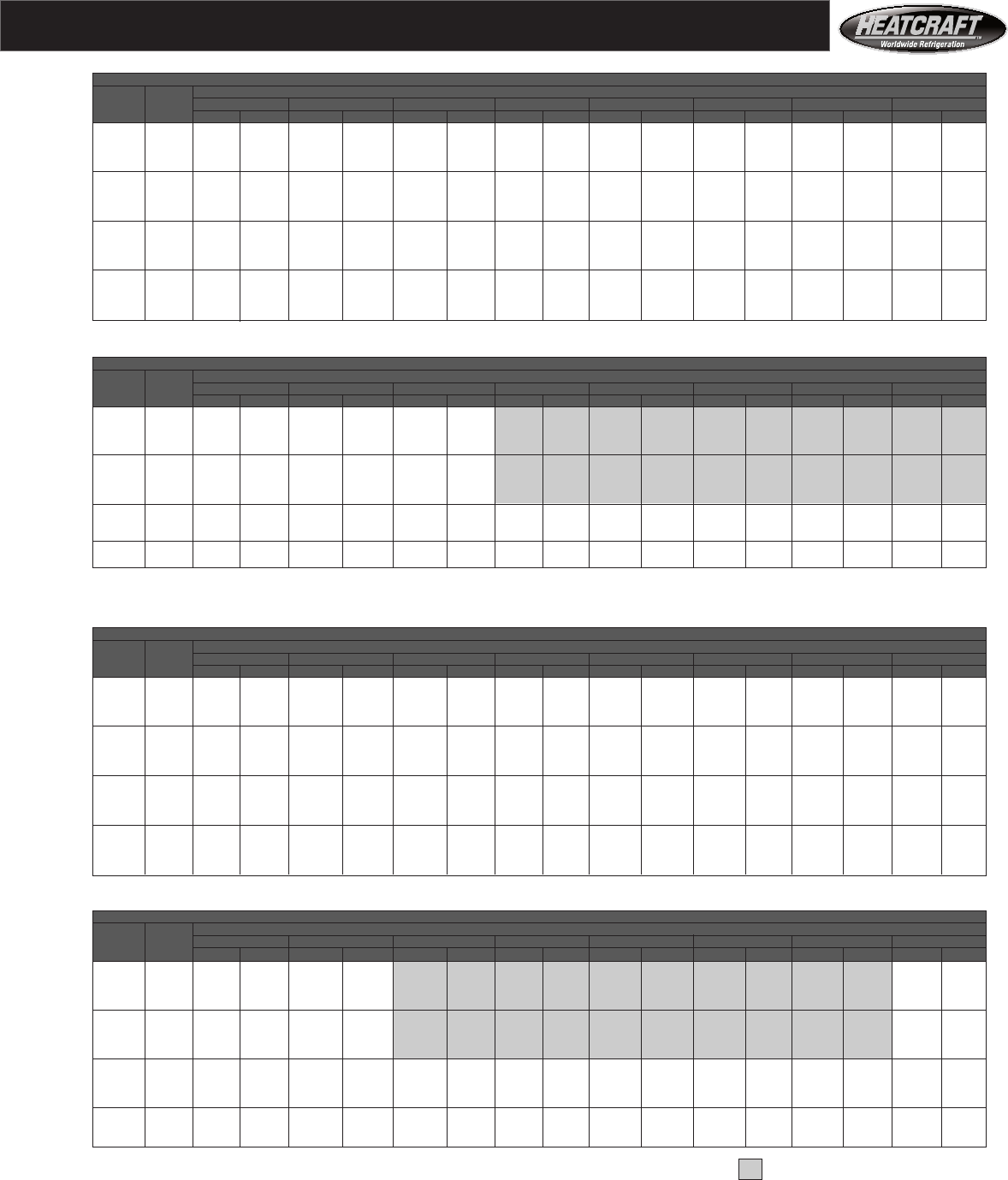
25
Size 10
Size 10
Fan Performance
Size 08
15" Forward Curved Fan
CFM Coil Total Static Pressure - Inches Of Water
Std. Vel. 0.50 1.00 1.25 1.50 1.75 2.00 2.25 2.50
Air FPM RPM BHP RPM BHP RPM BHP RPM BHP RPM BHP RPM BHP RPM BHP RPM BHP
2700 346 510 0.47 685 0.80 763 0.97 838 1.11 908 1.22 976 1.33 1041 1.47 1103 1.63
3000 384 524 0.56 691 0.93 765 1.11 836 1.30 904 1.46 970 1.63 1031 1.71 1092 1.84
3300 423 541 0.69 700 1.06 771 1.27 839 1.47 903 1.67 966 1.86 1027 2.04 1085 2.19
3600 461 559 0.82 712 1.20 780 1.42 845 1.65 906 1.88 966 2.10 1024 2.32 1080 2.52
3900 499 581 0.98 725 1.37 791 1.60 853 1.84 913 2.09 970 2.34 1025 2.58 1079 2.82
4200 538 602 1.18 739 1.56 803 1.80 864 2.05 921 2.31 977 2.58 1030 2.85 1082 3.11
4500 576 625 1.41 756 1.80 817 2.02 875 2.28 931 2.55 985 2.84 1037 3.12 1087 3.41
4800 615 648 1.67 773 2.07 832 2.28 889 2.53 943 2.81 995 3.11 1046 3.41 1095 3.72
5100 653 673 1.97 792 2.33 849 2.58 903 2.83 956 3.11 1007 3.40 1056 3.72 1104 4.04
5400 691 699 2.31 813 2.65 867 2.94 919 3.16 970 3.43 1020 3.73 1068 4.05 1114 4.38
5700 730 727 2.69 835 3.01 886 3.26 936 3.55 986 3.81 1034 4.10 1080 4.42 1126 4.76
6000 768 755 3.11 857 3.42 907 3.65 953 3.94 1002 4.23 1049 4.51 1094 4.83 1139 5.16
6300 807 784 3.57 879 3.87 928 4.09 974 4.36 1020 4.71 1065 4.97 1109 5.28 1152 5.61
6600 845 813 4.08 902 4.38 950 4.59 995 4.84 1038 5.15 1082 5.50 1125 5.79 1167 6.11
6900 883 844 4.65 926 4.93 972 5.13 1017 5.38 1059 5.67 1098 6.01 1142 6.36 1183 6.67
7200 922 874 5.25 951 5.54 995 5.73 1038 5.96 1080 6.25 1119 6.57 1160 6.99 1200 7.28
15" Forward Curved Fan
CFM Coil Total Static Pressure - Inches Of Water
Std. Vel. 2.50 3.00 3.50 4.00 4.50 5.00 5.50 6.00
Air FPM RPM BHP RPM BHP RPM BHP RPM BHP RPM BHP RPM BHP RPM BHP RPM BHP
2700 346 1103 1.63 1219 2.02 1323 2.45 1419 2.91 1507 3.39 1589 3.88 1665 4.39 1738 4.90
3000 384 1092 1.84 1207 2.17 1313 2.58 1411 3.05 1502 3.54 1587 4.06 1666 4.59 1740 5.14
3300 423 1085 2.19 1195 2.43 1301 2.78 1400 3.22 1493 3.70 1580 4.73 1661 4.77 1738 5.34
3600 461 1080 2.52 1189 2.85 1290 3.11 1388 3.47 1481 3.92 1569 4.42 1652 4.97 1731 5.54
3900 499 1079 2.82 1184 3.25 1284 3.62 1378 3.88 1469 4.25 1557 4.70 1641 5.22 1721 5.78
4200 538 1082 3.11 1182 3.62 1279 4.08 1372 4.50 1459 4.76 1545 5.12 1629 5.57 1709 6.09
4500 576 1087 3.41 1184 3.97 1277 4.51 1367 5.00 1455 5.50 1537 5.74 1618 6.10 1697 6.54
4800 615 1095 3.72 1188 4.33 1278 4.92 1365 5.49 1450 6.02 1533 6.51 1610 6.86 1687 7.19
5100 653 1104 4.04 1195 4.69 1282 5.33
5400 691 1114 4.38 1203 5.07 1288 5.75
5700 730 1126 4.76 1213 5.46
6000 768 1139 5.16 1224 5.88
6300 807 1152 5.61
Maximum ODP Motor Frame Size for Models 08 — 215 T
SIZE 08
18" Forward Curved Fan
CFM Coil Total Static Pressure - Inches Of Water
Std. Vel. 0.50 1.00 1.25 1.50 1.75 2.00 2.25 2.50
Air FPM RPM BHP RPM BHP RPM BHP RPM BHP RPM BHP RPM BHP RPM BHP RPM BHP
3200 328 438 0.51 597 0.92 665 1.14 730 1.36 793 1.59 852 1.82 908 2.05 961 2.29
3600 368 449 0.63 602 1.05 668 1.30 729 1.54 787 1.79 844 2.04 899 2.30 952 2.56
4000 409 461 0.79 609 1.20 673 1.46 732 1.73 789 2.00 841 2.28 893 2.56 944 2.84
4400 450 475 0.97 617 1.38 679 1.64 737 1.92 792 2.22 844 2.53 893 2.82 941 3.13
4800 491 491 1.18 627 1.60 687 1.86 744 2.14 797 2.45 848 2.78 896 3.11 943 3.44
5200 532 508 1.44 638 1.87 697 2.12 752 2.40 804 2.71 853 3.05 900 3.40 946 3.75
5600 573 525 1.74 651 2.18 707 2.43 761 2.70 812 3.01 860 3.34 906 3.70 951 4.07
6000 614 545 2.08 664 2.53 719 2.78 771 3.06 821 3.36 868 3.69 913 4.05 957 4.42
6400 655 566 2.45 679 2.92 732 3.19 783 3.47 831 3.76 877 4.09 921 4.44 964 4.82
6800 696 589 2.87 695 3.35 746 3.64 795 3.93 842 4.23 887 4.55 931 4.89 972 5.26
7200 737 613 3.33 714 3.85 761 4.14 809 4.44 854 4.75 898 5.07 941 5.41 982 5.77
7600 778 637 3.83 729 4.44 777 4.68 823 5.01 867 5.33 910 5.65 952 5.99 992 6.35
8000 819 662 4.38 746 5.06 797 5.30 838 5.62 881 5.96 923 6.30 964 6.64 1003 7.00
8400 860 687 4.99 766 5.73 811 6.02 855 6.28 896 6.65 937 7.00 976 7.35 1015 7.71
8800 901 712 5.64 787 6.46 828 6.79 874 7.04 912 7.38 951 7.76 990 8.13 1027 8.50
9200 942 738 6.36 810 7.24 847 7.61 888 7.91 928 8.17
18" Forward Curved Fan
CFM Coil Total Static Pressure - Inches Of Water
Std. Vel. 2.50 3.00 3.50 4.00 4.50 5.00 5.50 6.00
Air FPM RPM BHP RPM BHP RPM BHP RPM BHP RPM BHP RPM BHP RPM BHP RPM BHP
3200 328 961 2.29 1058 2.78 1146 3.28 1227 3.80 1302 4.34 1372 4.90
3600 368 952 2.56 1051 3.08 1141 3.62 1223 4.18 1300 4.75 1372 5.34
4000 409 944 2.84 1042 3.41 1132 3.99 1216 4.58 1295 5.19 1368 5.81
4400 450 941 3.13 1034 3.75 1123 4.37 1208 5.01 1287 5.65 1361 6.31
4800 491 943 3.44 1031 4.10 1116 4.77 1199 5.45 1278 6.14 1353 6.83
5200 532 946 3.75 1033 4.46 1113 5.18 1193 5.91 1270 6.64 1344 7.38 1415 8.13
5600 573 951 4.07 1035 4.84 1115 5.60 1190 6.37 1264 7.16 1337 7.95 1407 8.74
6000 614 957 4.42 1040 5.22 1118 6.05 1192 6.87 1262 7.69 1332 8.53 1400 9.37
6400 655 964 4.82 1045 5.63
6800 696 972 5.26 1052 6.07
7200 737 982 5.77 1060 6.58
7600 778 992 6.35
8000 819 1003 7.00
8400 860 1015 7.71
8800 901 1027 8.50
Maximum ODP Motor Frame Size for Models 10 — 215 T Medium Pressure Fan Must Be Used when
Coil Face Velocity is for a Large Cooling Coil, Type A (1/2" Tube Diameter) Operating in Shaded Area
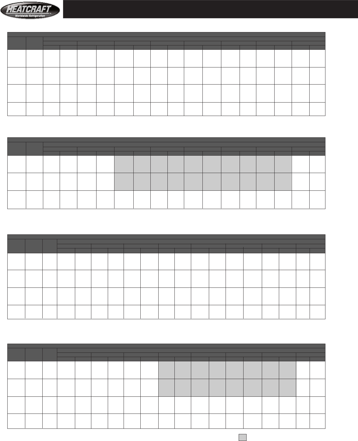
26
Size 14 and Size 18
Size 12
Maximum ODP Motor Frame Size for Models 14 & 18 — 254 T Medium Pressure Fan Must Be Used
Coil Face Velocity is for a Large Cooling Coil, Type A (1/2" Tube Diameter) When Operating in Shaded Area
Size 14 and Size 18
Fan Performance
Size 12
18" Forward Curved Fan
CFM Coil Total Static Pressure - Inches Of Water
Std. Vel. 0.50 1.00 1.25 1.50 1.75 2.00 2.25 2.50
Air FPM RPM BHP RPM BHP RPM BHP RPM BHP RPM BHP RPM BHP RPM BHP RPM BHP
4400 354 475 0.97 617 1.38 679 1.64 737 1.92 792 2.22 844 2.53 893 2.82 941 3.13
4800 306 491 1.18 627 1.60 687 1.86 744 2.14 797 2.45 848 2.78 896 3.11 943 3.44
5200 419 508 1.44 638 1.87 697 2.12 752 2.40 804 2.71 853 3.05 900 3.40 946 3.75
5600 451 525 1.74 651 2.18 707 2.43 761 2.70 812 3.01 860 3.34 906 3.70 951 4.07
6000 483 545 2.08 664 2.53 719 2.78 771 3.06 821 3.36 868 3.69 913 4.05 957 4.42
6400 515 566 2.45 679 2.92 732 3.19 783 3.47 831 3.76 877 4.09 921 4.44 964 4.82
6800 547 589 2.87 695 3.35 746 3.64 795 3.93 842 4.23 887 4.55 931 4.89 972 5.26
7200 580 613 3.33 714 3.85 761 4.14 809 4.44 854 4.75 898 5.07 941 5.41 982 5.77
7600 612 637 3.83 729 4.44 777 4.68 823 5.01 867 5.33 910 5.65 952 5.99 992 6.35
8000 644 662 4.38 746 5.06 797 5.30 838 5.62 881 5.96 923 6.30 964 6.64 1003 7.00
8400 676 687 4.99 766 5.73 811 6.02 855 6.28 896 6.65 937 7.00 976 7.35 1015 7.71
8800 708 712 5.64 787 6.46 828 6.79 874 7.04 912 7.38 951 7.76 990 8.13 1027 8.50
9200 741 738 6.36 810 7.24 847 7.61 888 7.91 928 8.17 967 8.58
9600 773 764 7.12 833 8.09 868 8.48
10000 805 790 7.94
18" Forward Curved Fan
CFM Coil Total Static Pressure - Inches Of Water
Std. Vel. 2.50 3.00 3.50 4.00 4.50 5.00 5.50 6.00
Air FPM RPM BHP RPM BHP RPM BHP RPM BHP RPM BHP RPM BHP RPM BHP RPM BHP
4400 354 941 3.13 1034 3.75 1123 4.37 1208 5.01 1287 5.65 1361 6.31 1432 6.98
4800 306 943 3.44 1031 4.10 1116 4.77 1199 5.45 1278 6.14 1353 6.83 1424 7.54
5200 419 946 3.75 1033 4.46 1113 5.18 1193 5.91 1270 6.64 1344 7.38 1415 8.13
5600 451 951 4.07 1035 4.84 1115 5.60 1190 6.37 1264 7.16 1337 7.95 1407 8.74
6000 483 957 4.42 1040 5.22 1118 6.05 1192 6.87 1262 7.69 1332 8.53 1400 9.37
6400 515 964 4.82 1045 5.63 1122 6.49 1195 7.37 1265 8.24 1331 9.11 1396 10.01
6800 547 972 5.26 1052 6.07 1128 6.95 1199 7.88 1268 8.81 1334 9.74 1396 10.66
7200 580 982 5.77 1060 6.58 1134 7.46 1204 8.40 1272 9.38 1337 10.37 1399 11.36
7600 612 992 6.35
8000 644 1003 7.00
8400 676 1015 7.71
8800 708 1027 8.50
Maximum ODP Motor Frame Size for Model 12 — 254T
20" Forward Curved Fan
CFM Coil Vel Total Static Pressure - Inches Of Water
Std. Size Size 0.50 1.00 1.25 1.50 1.75 2.00 2.25 2.50
Air 14 18 RPM BHP RPM BHP RPM BHP RPM BHP RPM BHP RPM BHP RPM BHP RPM BHP
5400 370 — 386 0.88 518 1.42 577 1.72 634 2.01 686 2.24 738 2.53 789 2.87 836 3.25
5900 405 — 395 1.04 522 1.61 578 1.92 632 2.25 684 2.57 733 2.82 781 3.11 828 3.46
6400 439 361 403 1.22 528 1.82 582 2.15 633 2.50 682 2.85 731 3.20 777 3.48 821 3.77
6900 473 390 413 1.40 535 2.07 587 2.40 637 2.76 684 3.14 729 3.52 775 3.90 819 4.23
7400 508 418 423 1.61 543 2.35 594 2.69 642 3.06 687 3.45 731 3.85 774 4.26 816 4.67
7900 542 446 434 1.89 551 2.66 601 3.02 648 3.39 692 3.79 734 4.20 776 4.63 816 5.07
8400 576 474 446 2.18 559 2.99 609 3.38 655 3.76 698 4.17 739 4.59 779 5.03 818 5.49
8900 610 503 459 2.48 568 3.33 617 3.77 662 4.17 705 4.59 745 5.02 784 5.47 822 5.94
9400 645 531 472 2.82 577 3.69 625 4.18 670 4.62 712 5.05 752 5.49 790 5.95 827 6.42
9900 679 559 486 3.18 587 4.05 634 4.61 678 5.10 720 5.55 759 6.01 797 6.47 833 6.95
10400 713 587 500 3.56 597 4.49 643 5.06 687 5.60 728 6.09 767 6.57 804 7.05 839 7.54
10900 748 615 514 3.98 608 5.03 653 5.51 696 6.12 736 6.66 775 7.17 811 7.67 846 8.17
11400 782 644 529 4.44 620 5.59 663 5.98 705 6.66 745 7.26 783 7.81 819 8.33 854 8.85
11900 816 672 544 4.93 632 6.18 674 6.65 715 7.20 754 7.87 791 8.47 827 9.04 861 9.58
12400 850 700 560 5.46 644 6.79 685 7.33 725 7.74 763 8.50 800 9.16 835 9.77 869 10.35
20" Forward Curved Fan
CFM Coil Vel Total Static Pressure - Inches Of Water
Std. Size Size 2.50 3.00 3.50 4.00 4.50 5.00 5.50 6.00
Air 14 18 RPM BHP RPM BHP RPM BHP RPM BHP RPM BHP RPM BHP RPM BHP RPM BHP
5400 370 — 836 3.25 924 4.09 1001 5.02 1071 6.02 1135 7.06 1195 8.15 1250 9.27
5900 405 — 828 3.46 916 4.26 997 5.18 1070 6.18 1136 7.24 1198 8.35 1255 9.51
6400 439 361 821 3.77 908 4.51 989 5.39 1065 6.37 1133 7.43 1197 8.56 1256 9.73
6900 473 390 819 4.23 901 4.86 981 5.67 1057 6.61 1128 7.66 1193 8.78 1254 9.96
7400 508 418 816 4.67 897 5.37 973 6.08 1048 6.94 1120 7.94 1187 9.04 1250 10.21
7900 542 446 816 5.07 895 5.94 969 6.64 1041 7.41 1111 8.33 1178 9.38 1243 10.52
8400 576 474 818 5.49 894 6.42 968 7.33 1037 8.05 1104 8.87 1170 9.84 1234 10.92
8900 610 503 822 5.94 895 6.91 965 7.90 1035 8.85 1099 9.59 1163 10.45 1226 11.45
9400 645 531 827 6.42 897 7.42 966 8.46
9900 679 559 833 6.95 902 7.97 968 9.05
10400 713 587 839 7.54 907 8.57 971 9.66
10900 748 615 846 8.17 913 9.22 976 10.33
11400 782 644 854 8.85 919 9.92 982 11.04
11900 816 672 861 9.58 926 10.68 988 11.82
12400 850 700 869 10.35 934 11.49 994 12.65
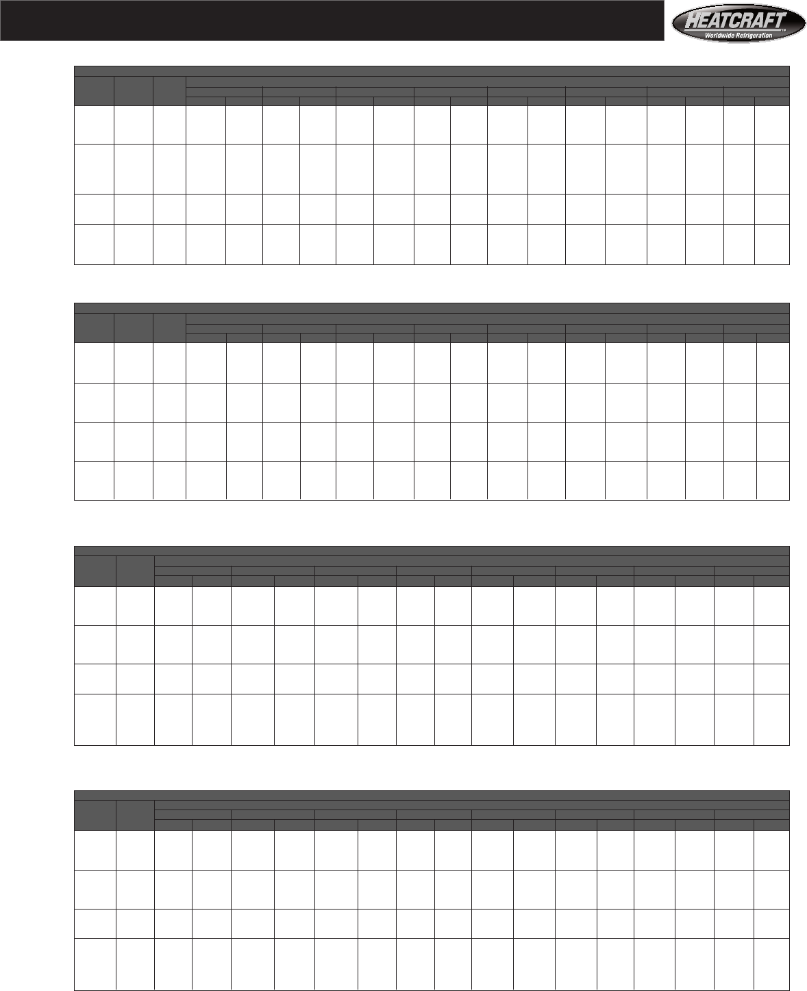
27
Fan Performance
Size 34
25" Forward Curved Fan
CFM Coil Total Static Pressure - Inches Of Water
Std. Vel. 2.50 3.00 3.50 4.00 4.50 5.00 5.50 6.00
Air FPM RPM BHP RPM BHP RPM BHP RPM BHP RPM BHP RPM BHP RPM BHP RPM BHP
9000 267 680 5.30 744 6.47 800 7.71 851 9.00 899 10.34 943 11.74 985 13.18
10000 297 679 5.82 746 7.05 804 8.34 857 9.68 906 11.08 951 12.53 994 14.02
11000 327 673 6.42 744 7.68 805 9.02 860 10.42 911 11.87 958 13.37 1001 14.92
12000 357 664 7.16 738 8.41 803 9.77 861 11.22 913 12.72 961 14.28 1007 15.88
13000 386 662 7.61 729 9.27 797 10.63 857 12.10 912 13.65 963 15.25 1009 16.91
14000 416 663 8.22 725 9.87 788 11.63 851 13.09 908 14.66 961 16.30 1009 18.01
15000 446 667 8.99 726 10.53 784 12.37 842 14.25 902 15.81 956 17.46 1007 19.20
16000 475 672 9.89 729 11.39 784 13.09 838 15.09 893 17.14 949 18.77 1001 20.51
17000 505 677 10.89 733 12.41 786 14.05 838 15.90 889 18.03 940 20.29 993 22.00
18000 535 684 11.98 738 13.55 790 15.19
19000 565 690 13.14 744 14.80
20000 594 697 14.37 751 16.13
21000 624 704 15.67 757 17.54
22000 654 712 17.03 764 19.03
23000 684 720 18.47 772 20.59
24000 713 728 20.00 779 22.23
Maximum ODP Motor Frame Size for Models 34 — 324 T
Coil Face Velocity is for a Large Cooling Coil, Type A (1/2" Tube Diameter)
Size 34
25" Forward Curved Fan
CFM Coil Total Static Pressure - Inches Of Water
Std. Vel. 0.50 1.00 1.25 1.50 1.75 2.00 2.25 2.50
Air FPM RPM BHP RPM BHP RPM BHP RPM BHP RPM BHP RPM BHP RPM BHP RPM BHP
9000 267 312 1.30 420 2.12 468 2.65 517 3.19 565 3.67 607 4.19 645 4.73 680 5.30
10000 297 319 1.57 424 2.46 469 2.94 513 3.52 556 4.17 601 4.68 642 5.24 679 5.82
11000 327 327 1.87 430 2.86 473 3.35 514 3.89 554 4.50 593 5.25 634 5.84 673 6.42
12000 357 337 2.23 436 3.32 479 3.84 518 4.38 556 4.96 592 5.61 628 6.37 664 7.16
13000 386 347 2.62 443 3.81 485 4.39 524 4.96 560 5.54 595 6.16 629 6.85 662 7.61
14000 416 358 3.07 451 4.36 492 4.99 530 5.60 565 6.22 599 6.84 632 7.50 663 8.22
15000 446 370 3.60 459 4.95 499 5.64 537 6.31 572 6.97 605 7.62 636 8.29 667 8.99
16000 475 385 4.21 467 5.60 507 6.34 544 7.07 578 7.78 611 8.48 642 9.18 672 9.89
17000 505 400 4.89 477 6.32 515 7.10 551 7.88 585 8.65 617 9.41 648 10.15 677 10.89
18000 535 415 5.67 487 7.11 524 7.92 559 8.75 592 9.58 624 10.39 655 11.19 684 11.98
19000 565 432 6.53 497 7.95 533 8.83 567 9.69 600 10.57 632 11.44 662 12.30 690 13.14
20000 594 448 7.49 508 8.89 544 9.82 576 10.71 608 11.63 639 12.55 669 13.47 697 14.37
21000 624 465 8.54 521 9.95 553 10.84 586 11.83 617 12.77 647 13.74 676 14.71 704 15.67
22000 654 482 9.71 535 11.11 564 11.99 597 13.01 626 14.00 655 15.00 684 16.02 712 17.03
23000 684 500 10.98 549 12.39 576 13.26 606 14.25 637 15.34 665 16.36 692 17.41 720 18.47
24000 713 518 12.36 565 13.78 590 14.65 617 15.62 646 16.72 674 17.83 701 18.90 728 20.00
Size 20 and Size 26
22" Forward Curved Fan
CFM Coil Vel Total Static Pressure - Inches Of Water
Std. Size Size 2.50 3.00 3.50 4.00 4.50 5.00 5.50 6.00
Air 20 26 RPM BHP RPM BHP RPM BHP RPM BHP RPM BHP RPM BHP RPM BHP RPM BHP
8500 424 — 775 5.39 850 6.51 922 7.76 989 9.07 1051 10.43 1109 11.81 1163 13.22
9000 449 — 778 5.77 849 6.85 919 8.08 986 9.42 1049 10.81 1108 12.25 1163 13.71
9500 474 — 782 6.17 850 7.25 917 8.45 983 9.78 1046 11.20 1106 12.67 1162 14.18
10000 499 — 786 6.59 853 7.72 917 8.88 981 10.18 1044 11.60 1103 13.10 1160 14.65
10500 524 395 789 7.02 857 8.20 920 9.39 980 10.65 1041 12.05 1100 13.55 1157 15.13
11000 549 414 793 7.47 861 8.70 923 9.95 981 11.20 1040 12.56 1098 14.04 1154 15.62
11500 574 433 797 7.94 865 9.23 927 10.52 985 11.82 1040 13.14 1096 14.59 1151 16.16
12000 599 452 802 8.44 869 9.77 931 11.11 989 12.47 1043 13.82 1096 15.22 1150 16.76
12500 623 471 806 8.96 873 10.33 935 11.72 993 13.13 1047 14.54 1099 15.96 1149 17.44
13000 648 489 810 9.50 877 10.92 939 12.36 996 13.81 1051 15.28 1102 16.75 1152 18.22
14000 698 527 819 10.67 885 12.17
15000 — 565 828 11.96 894 13.54
16000 — 602 839 13.39 903 15.04
17000 — 640 851 14.96 913 16.67
18000 — 678 866 16.69 925 18.46
19000 — 715 882 18.60
Maximum ODP Motor Frame Size for Models 20 and 26 — 256T
Size 20 and Size 26
22" Forward Curved Fan
CFM Coil Vel Total Static Pressure - Inches Of Water
Std. Size Size 0.50 1.00 1.25 1.50 1.75 2.00 2.25 2.50
Air 20 26 RPM BHP RPM BHP RPM BHP RPM BHP RPM BHP RPM BHP RPM BHP RPM BHP
8500 424 — 394 1.66 514 2.53 567 2.99 614 3.46 658 3.94 699 4.42 738 4.90 775 5.39
9000 449 — 403 1.88 519 2.77 571 3.25 618 3.75 662 4.25 703 4.75 741 5.26 778 5.77
9500 474 — 412 2.10 524 3.03 575 3.53 622 4.05 666 4.57 707 5.10 745 5.63 782 6.17
10000 499 — 421 2.35 529 3.32 580 3.84 627 4.37 670 4.91 711 5.47 749 6.02 786 6.59
10500 524 395 432 2.63 535 3.62 585 4.16 631 4.71 674 5.28 715 5.85 753 6.43 789 7.02
11000 549 414 443 2.94 542 3.95 590 4.50 636 5.08 679 5.66 719 6.26 757 6.86 793 7.47
11500 574 433 455 3.27 549 4.31 595 4.87 640 5.46 683 6.07 723 6.69 761 7.31 797 7.94
12000 599 452 467 3.64 557 4.69 602 5.27 645 5.88 688 6.50 728 7.14 766 7.78 802 8.44
12500 623 471 480 4.04 566 5.11 609 5.70 651 6.32 692 6.96 732 7.61 770 8.28 806 8.96
13000 648 489 493 4.47 575 5.55 616 6.15 657 6.79 698 7.44 737 8.12 774 8.80 810 9.50
14000 698 527 521 5.44 593 6.50 633 7.16 671 7.82 709 8.51 747 9.21 784 9.94 819 10.67
15000 — 565 549 6.56 614 7.61 651 8.28 688 8.99 723 9.70 759 10.44 794 11.19 828 11.96
16000 — 602 578 7.84 637 8.89 670 9.54 706 10.30 739 11.04 773 11.80 806 12.58 839 13.39
17000 — 640 607 9.27 662 10.35 692 10.99 724 11.72 758 12.54 789 13.32 820 14.13 851 14.96
18000 — 678 636 10.88 688 11.98 715 12.62 744 13.34 775 14.14 807 15.01 836 15.84 866 16.69
19000 — 715 666 12.67 715 13.79 740 14.45 767 15.16 794 15.94 824 16.81 854 17.72 882 18.60
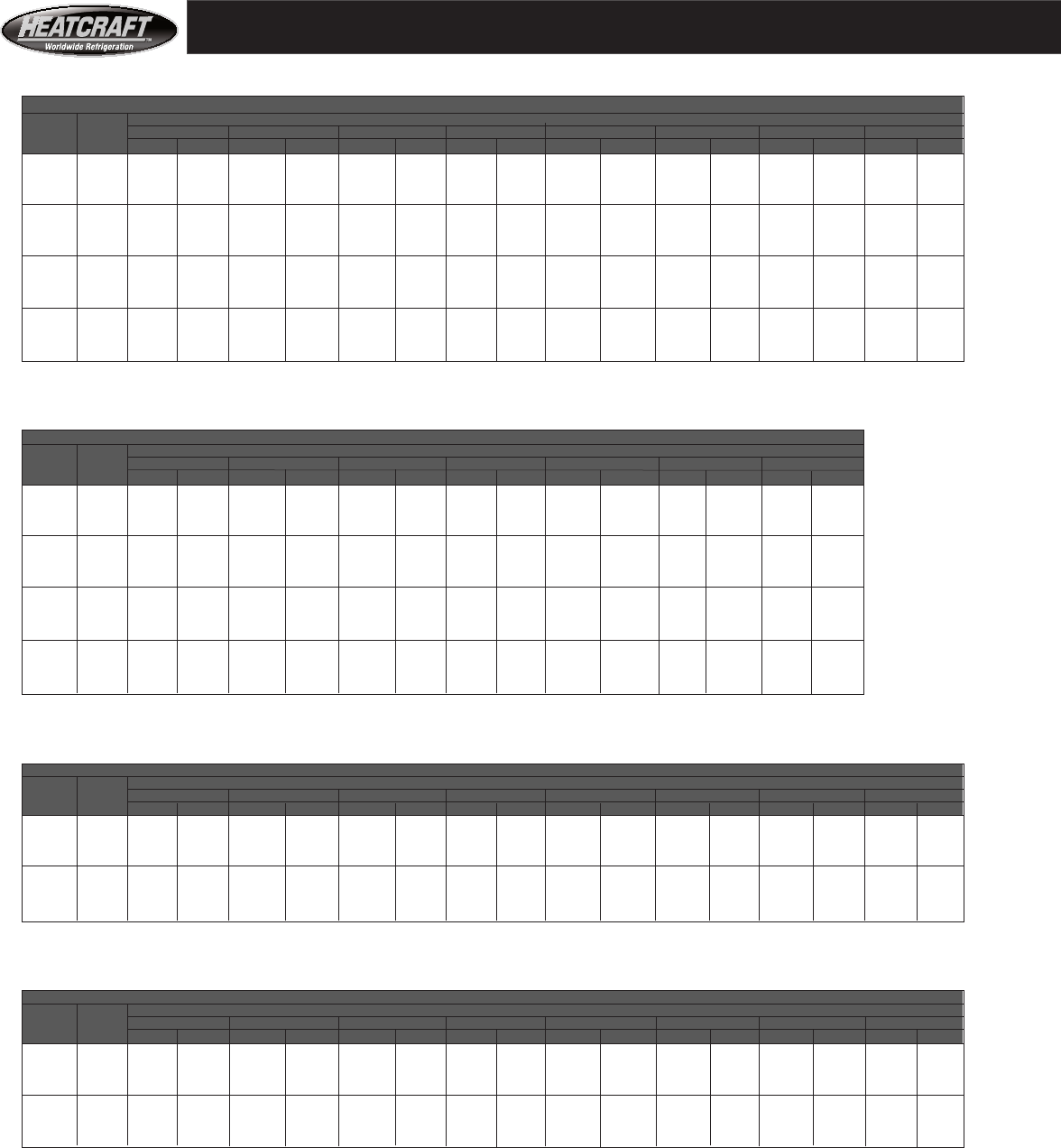
28
Maximum ODP Motor Frame Size for Models 41 — 324 T
Fan Performance
Size 41
30" Forward Curved Fan
CFM Coil Total Static Pressure - Inches Of Water
Std. Vel. 0.50 1.00 1.25 1.50 1.75 2.00 2.25 2.50
Air FPM RPM BHP RPM BHP RPM BHP RPM BHP RPM BHP RPM BHP RPM BHP RPM BHP
17000 418 265 3.07 348 4.81 383 5.65 416 6.50 447 7.37 477 8.29 506 9.27 542 10.53
18000 443 270 3.43 352 5.28 386 6.17 418 7.06 449 7.96 478 8.89 506 9.87 534 10.91
19000 468 277 3.87 355 5.77 389 6.72 421 7.66 451 8.60 479 9.56 507 10.55 533 11.58
20000 492 282 4.31 359 6.28 393 7.30 424 8.30 453 9.29 481 10.28 508 11.29 534 12.33
21000 517 288 4.80 363 6.83 396 7.91 427 8.97 456 10.01 484 11.04 510 12.09 535 13.15
22000 541 295 5.34 367 7.40 400 8.54 431 9.66 459 10.76 486 11.85 512 12.94 537 14.04
23000 566 302 5.92 371 8.01 404 9.21 434 10.39 463 11.55 489 12.70 515 13.83 539 14.97
24000 591 309 6.56 375 8.66 407 9.91 438 11.15 466 12.38 493 13.58 518 14.77 542 15.95
25000 615 317 7.24 379 9.36 411 10.64 441 11.95 470 13.23 496 14.50 521 15.74 545 16.98
26000 640 324 7.98 387 10.23 416 11.42 445 12.78 473 14.13 499 15.45 524 16.76 548 18.05
27000 664 332 8.78 392 11.06 420 12.25 449 13.65 477 15.05 503 16.44 528 17.81 551 19.16
28000 689 340 9.63 398 11.94 425 13.12 453 14.56 481 16.02 507 17.47 531 18.90 555 20.32
29000 714 348 10.55 404 12.88 432 14.23 458 15.52 485 17.03 510 18.54 535 20.03 558 21.51
30000 738 357 11.52 410 13.89 437 15.25 462 16.53 489 18.08 514 19.64 538 21.20 562 22.74
31000 763 365 12.57 417 14.97 443 16.34 467 17.61 493 19.19 518 20.80 542 22.41 565 24.02
32000 788 374 13.67 424 16.12 449 17.49 475 18.99 497 20.35 522 22.00 546 23.67 569 25.33
Size 41
30" Forward Curved Fan
CFM Coil Total Static Pressure - Inches Of Water
Std. Vel. 2.50 3.00 3.50 4.00 4.50 5.00 5.50
Air FPM RPM BHP RPM BHP RPM BHP RPM BHP RPM BHP RPM BHP RPM BHP
17000 418 542 10.53 608 13.20 664 15.89 714 18.59 758 21.28 799 23.98 837 26.69
18000 443 534 10.91 600 13.60 659 16.45 710 19.30 757 22.15 799 25.00 838 27.86
19000 468 533 11.58 590 13.99 651 16.94 706 19.95 754 22.96 798 25.97 838 28.98
20000 492 534 12.33 584 14.55 643 17.39 699 20.52 749 23.69 795 26.87 837 30.04
21000 517 535 13.15 584 15.38 632 17.85 690 21.05 743 24.36 790 27.69 834 31.02
22000 541 537 14.04 585 16.30 631 18.71 681 21.56 735 24.96 784 28.43 829 31.92
23000 566 539 14.97 586 17.29 631 19.71 675 22.31 725 25.54 776 29.11 823 32.74
24000 591 542 15.95 588 18.34 632 20.80 675 23.40 716 26.17 767 29.75 815 33.50
25000 615 545 16.98 591 19.45 634 21.97 675 24.59 716 27.35 757 30.40 806 34.21
26000 640 548 18.05 593 20.62 636 23.21 676 25.86 716 28.71
27000 664 551 19.16 596 21.84 638 24.51 678 27.22 717 30.08
28000 689 555 20.32 599 23.10 640 25.87 680 28.65 718 31.59
29000 714 558 21.51 602 24.41 643 27.28 682 30.15 720 33.15
30000 738 562 22.74 605 25.77 646 28.75 685 31.71 722 34.79
31000 763 565 24.02 609 27.17 649 30.27 688 33.33 724 36.50
32000 788 569 25.33 612 28.62 653 31.83 691 35.01 726 38.21
Size 50
32 3/8" Airfoil Fan
CFM Coil Total Static Pressure - Inches Of Water
Std. Vel. 0.50 1.00 1.25 1.50 1.75 2.00 2.25 2.50
Air FPM RPM BHP RPM BHP RPM BHP RPM BHP RPM BHP RPM BHP RPM BHP RPM BHP
17000 349 679 3.44 750 4.90 783 5.64 815 6.38 845 7.13 875 7.89 903 8.66 931 9.44
19000 390 744 4.52 809 6.15 840 6.96 870 7.76 899 8.58 927 9.38 954 10.21 978 11.02
21000 431 809 5.82 868 7.60 897 8.48 925 9.32 953 10.22 979 11.04 1005 11.93 1027 12.81
23000 472 873 6.92 928 8.86 955 9.84 981 10.83 1006 11.82 1031 12.81 1056 13.81 1079 14.82
25000 522 938 9.07 987 11.16 1012 12.18 1036 13.10 1060 14.07 1083 14.95 1107 15.95 1133 17.05
27000 554 1003 11.09 1046 13.29 1069 14.35 1091 15.30 1114 16.33 1135 17.22 1158 18.26 1189 19.53
29000 595 1068 13.39 1105 15.67 1126 16.77 1146 17.73 1168 18.82 1187 19.69 1209 20.78 1246 22.28
31000 636 1133 15.98 1164 18.32 1183 19.45 1201 20.41 1222 21.56 1239 22.40 1260 23.53 1305 25.31
Size 50
32 3/8" Airfoil Fan
CFM Coil Total Static Pressure - Inches Of Water
Std. Vel. 2.50 3.00 3.50 4.00 4.50 5.00 5.50 6.00
Air FPM RPM BHP RPM BHP RPM BHP RPM BHP RPM BHP RPM BHP RPM BHP RPM BHP
17000 349 931 9.44 982 11.06 1032 12.85 1080 14.64 1126 16.46 1172 18.32 1216 20.22
19000 390 978 11.02 1028 12.75 1074 14.45 1120 16.46 1164 18.45 1207 20.46 1249 22.49
21000 431 1027 12.81 1076 14.68 1122 16.58 1166 18.50 1206 20.51 1247 22.72 1287 24.92
23000 472 1079 14.82 1125 16.84 1170 18.88 1212 20.95 1254 23.05 1293 25.17 1329 27.44
25000 522 1133 17.05 1177 19.23 1220 21.43 1261 23.64 1300 25.89 1339 28.15 1376 30.44
27000 554 1189 19.53 1231 21.87 1272 24.23 1311 26.60 1349 28.99 1386 31.41 1422 33.83
29000 595 1246 22.28 1286 24.78 1325 27.29 1363 29.83 1400 32.37 1436 34.94
31000 636 1305 25.31 1343 27.98 1381 30.66 1417 33.35 1452 36.05
Maximum ODP Motor Frame Size for Models 50 — 324 T
Coil Face Velocity is for a Large Cooling Coil, Type A (1/2" Tube Diameter)
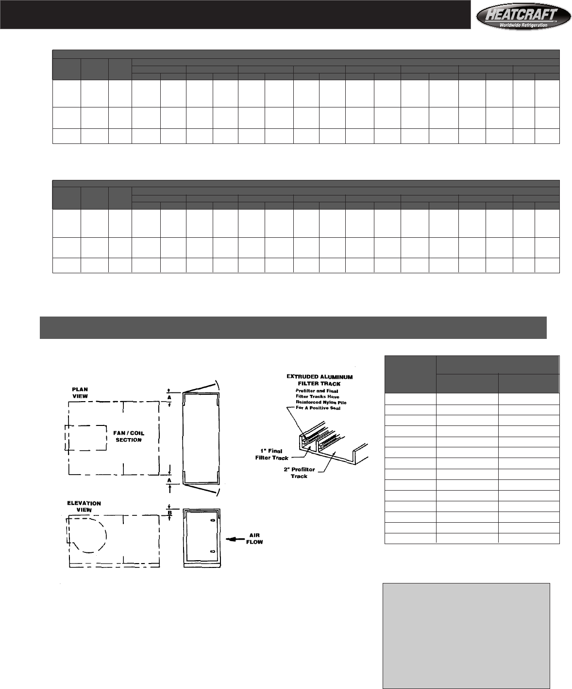
29
22" Section accommodates 2" prefilter and
up to an additional 12" of high efficiency
final filter
28" Section accommodates 2" prefilter and
up to an additional 21" of high efficiency
final filter
44" Section accommodates 2" prefilter and
up to an additional 37" of high efficiency
final filter
Fan Performance
Size 65 and Size 75
39 3/8" Airfoil Fan
CFM Coil Vel Total Static Pressure - Inches Of Water
Std. Size Size 0.50 1.00 1.25 1.50 1.75 2.00 2.25 2.50
Air 65 75 RPM BHP RPM BHP RPM BHP RPM BHP RPM BHP RPM BHP RPM BHP RPM BHP
23000 356 — 506 4.32 562 6.06 592 7.04 620 8.01 645 9.00 669 9.99 693 11.01 715 12.04
25500 395 — 550 5.48 597 7.31 625 8.35 653 9.43 678 10.51 702 11.60 724 12.70 746 13.81
28000 434 372 595 6.85 638 8.82 661 9.94 686 11.03 711 12.21 735 13.39 757 14.59 778 15.78
30500 472 405 640 8.44 680 10.59 700 11.68 719 12.80 744 14.10 768 15.39 790 16.68 811 17.97
33000 511 438 685 10.30 724 12.62 742 13.78 760 14.98 777 16.17 801 17.59 823 18.98 844 20.37
35500 550 471 731 12.40 768 14.94 785 16.17 801 17.42 818 18.72 836 20.11 856 21.50 877 23.01
38000 588 504 776 14.77 813 17.55 829 18.86 845 20.20 860 21.54 876 22.94 891 24.36 910 25.87
40500 627 537 822 17.48 858 20.47 873 21.88 888 23.29 903 24.71 917 26.16 930 27.29 943 28.78
43000 666 571 868 20.47 903 23.72 918 25.23 932 26.73 946 28.23 960 29.75 974 31.82 988 33.11
Size 65 and Size 75
39 3/8" Airfoil Fan
CFM Coil Vel Total Static Pressure - Inches Of Water
Std. Size Size 2.50 3.00 3.50 4.00 4.50 5.00 5.50 6.00
Air 65 75 RPM BHP RPM BHP RPM BHP RPM BHP RPM BHP RPM BHP RPM BHP RPM BHP
23000 356 — 715 12.04 755 14.17 799 16.56 840 18.75 880 21.56 925 23.78 974 26.15 1015 29.01
25500 395 — 746 13.81 781 16.00 824 18.39 863 20.86 901 23.21 947 25.8 990 28.52 1027 32.14
28000 434 372 778 15.78 819 18.28 851 20.77 886 23.45 926 25.89 973 28.61 1011 31.43 1044 34.14
30500 472 405 811 17.97 843 20.56 880 23.52 920 25.83 958 28.75 1003 31.51 1031 34.66 1066 38.18
33000 511 438 844 20.37 878 23.33 920 25.93 949 28.61 989 31.41 1025 35.01 1056 38.43
35500 550 471 877 23.01 910 26.10 947 29.08 986 32.16 1018 33.63 1047 38.71
38000 588 504 910 25.87 951 29.29 978 31.78 1016 34.04 1048 36.18
40500 627 537 943 28.78 984 32.45 1021 36.16
43000 666 571 988 33.11 1029 37.10
Maximum ODP Motor Frame Size for Models 65 and 75 — 324T for Open Drip Proof Motor and 286T for TEFC Motor.
High Efficiency Filter Sections- Dimensions
High Efficiency Filter Section
UNIT Dimensions - inches
SIZE A B
Width Height
03 0 3 1/2
06 0 1/4
08 0 3
10 3/8 3
12 0 0
14 0 0
18 0 0
20 2 1/4 0
26 1 1/2 0
34 1 1/2 0
41 1 1/2 0
50 0 0
65 0 0
75 0 3 3/8
Notes:
1. The high efficiency filter housing has flanges on the entering and leaving
air sides that match the Heatcraft Products accessory hole pattern (page 30).
2. The access doors have gaskets. Access doors are located on both sides
of the filter housing.
3. Filter housing is manufactured from a minimum of 16 gauge steel.
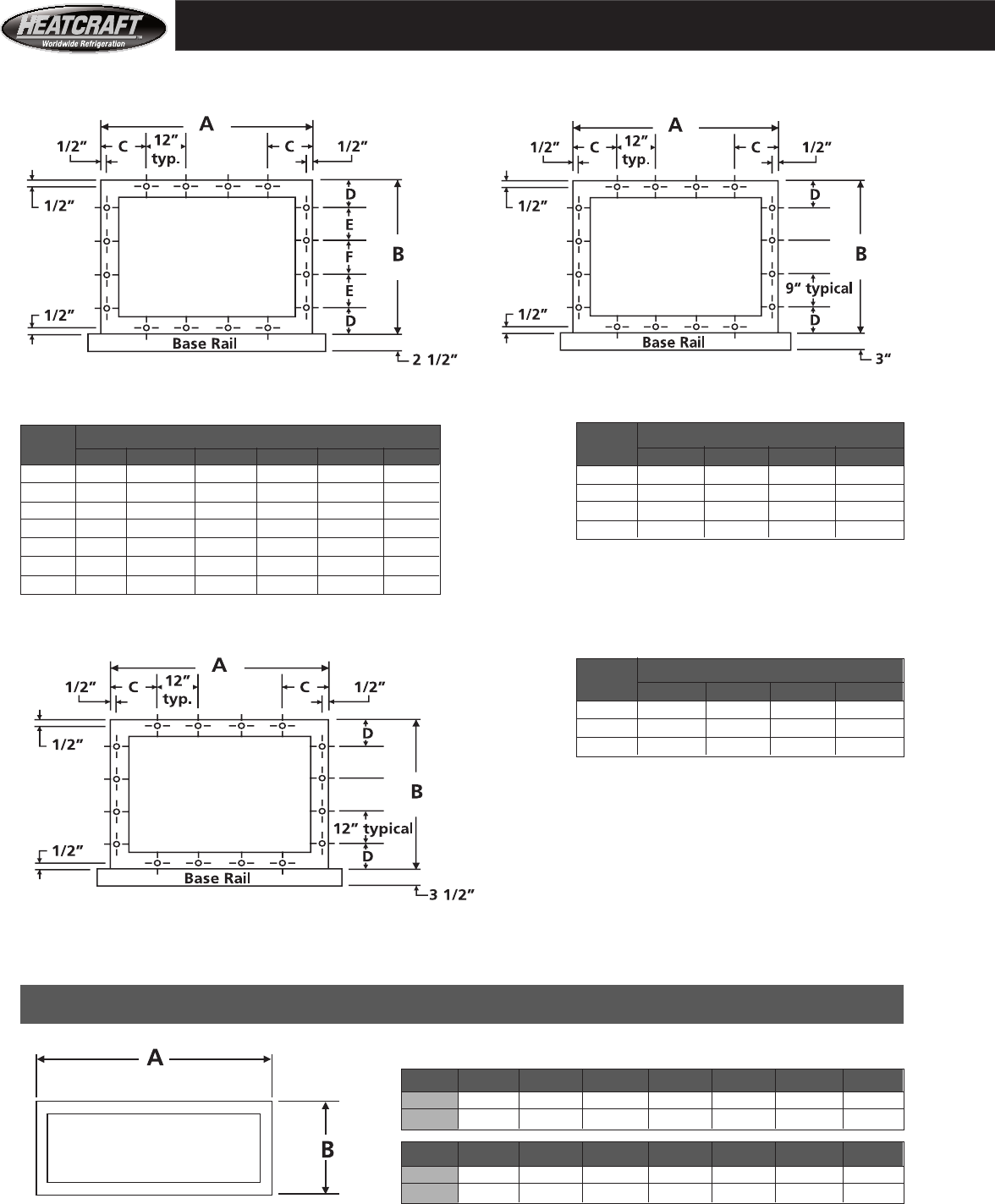
30
Sizes 03 - 18 Sizes 20 - 41
Accessory Flange Pattern
Sizes 50 - 75
Dimensions
Size A B C D
50 117 3/4 74 3/4 4 7/8 7 3/8
65 133 3/4 82 3/4 6 7/8 5 3/8
75 133 3/4 94 3/4 6 7/8 5 3/8
Notes - Sizes 03 Through 75:
Accessory hole patterns apply to both the
inlet and outlet of all the following sections:
Coil sections.
Flat and high efficiency filter sections.
High capacity filter sections and Access sections.
Internal face and bypass sections.
Accessory hole patterns apply to the:
Inlet of fan sections.
Flanges are 2", all sections. Inlet of external face and bypass sections.
Outlet of economizer sections.
Flanges are 1" minimum all sections.
Dimensions Dimensions
Size A B C D E F Size A B C D
03 37 22 3/4 1/2 2 3/8 9 — 20 90 44 3 4
06 52 26 2 4 9 — 26 115 44 3 1/2 4
08 49 35 1/2 1/2 5 3/4 12 — 34 115 54 3 1/2 4 1/2
10 58 35 1/2 5 5 3/4 12 — 41 115 65 3 1/2 5 1/2
12 64 38 3/4 2 4 3/8 12 6
14 73 38 3/4 6 1/2 4 3/8 12 6
18 73 47 3/4 6 1/2 5 1/2 12 1/4 —
Sizes 03 - 75
SIZE 03 06 08 10 12 14 18
A 35 50 47 56 62 71 71
B 12 1/2 12 1/2 12 1/2 12 1/2 12 1/2 15 1/4 15 1/4
SIZE 20 26 34 41 50 65 75
A 88 113 113 113 115 3/4 131 3/4 131 3/4
B 15 1/4 15 1/4 21 26 3/4 32 1/2 32 1/2 32 1/2
All dimensions are in inches. Flanges:
All sizes = 1"
Mixbox Inlet Duct Connections
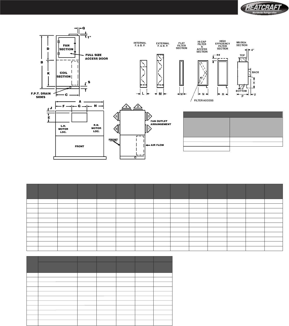
31
Dimensions
Model VCS
Sizes 03 - 41 FC
For All Unit Sizes
R** W
22" 6
28" 8
44"
** See page 29 for high efficiency filter section
height and width.
Arrangements Available:
Sizes 03 through 18 — Arrangements 1, 2, 3, 4, 5, 6.^^
Sizes 20 through 41 — Arrangements 2, 3, 4, 5.^^
A B C D E F* G H* J K L M^^ N
Unit air handler air handler air handler fan section fan outlet fan outlet fan outlet fan outlet discharge coil section int. F&BP ext. F&BP high cap.
Size width height depth height length locator width locator arr 1,2,5,6 verical data depth depth filter, depth
03 39 49 1/2 28 11/16 —— 10 1/4 18 1/8 11 7/8 9 1 1/2 —— 7 3/4 8 1/2 26 1/2
06 52 56 28 11/16 —— 13 7/16 18 3/16 15 5/8 18 3/16 1 1/2 —— 7 3/4 8 1/2 25 5/8
08 49 73 1/2 35 1/2 —— 15 7/8 17 1/8 14 3/4 17 1/8 1 1/2 —— 7 3/4 13 28 3/4
10 58 73 1/2 35 1/2 —— 18 7/8 20 5/16 17 3/8 20 5/16 1 1/2 —— 7 3/4 13 28 3/4
12 64 80 38 3/4 —— 18 7/8 23 5/16 17 3/8 23 5/16 1 1/2 —— 7 3/4 14 28 3/4
14 73 80 38 3/4 —— 24 3/4 25 1/8 22 3/4 25 1/8 2 1/2 —— 7 3/4 14 27 3/4
18 73 89 38 3/4 38 3/4 24 3/4 25 1/8 22 3/4 25 1/8 2 1/2 47 3/4 7 3/4 14 27 3/4
20 90 91 44 44 27 1/4 31 3/8 27 1/4 31 3/8 4 44 10 15 23
26 115 91 44 44 27 1/4 43 7/8 27 1/4 43 7/8 4 44 10 15 23
34 115 109 54 52 31 1/4 41 7/8 31 1/4 41 7/8 3 54 10 15 23
41 115 133 62 65 36 3/4 39 1/8 36 3/4 39 1/8 4 65 10 18 26 5/8
P Q+ S U V X Reference
Unit Mix box discharge air handler back inlet inlet back inlet
Size without filter section arr 3 & 4 base height depth height locator Motor and coil connection
03 20 1/2 1 1/2 2 1/2 5 1/2 4 5 1/8 locations (R.H or L.H.)
06 20 1/2 1 1/2 2 1/2 5 1/2 4 9 1/4 determined facing the front
08 20 1/2 1 1/2 2 1/2 5 1/2 4 14 of the unit, with the air
10 20 1/2 1 1/2 2 1/2 5 1/2 4 14 blowing through the coil
12 20 1/2 1 1/2 2 1/2 5 1/2 4 15 5/8 and into observer’s face.
14 23 1/4 2 1/2 2 1/2 7 5 1/2 14 1/4
18 23 1/4 2 1/2 2 1/2 7 5 1/2 18 3/4 ^^External Face & Bypass Note
20 23 1/4 2 3 7 5 1/2 17 3/8 Arrangements 1 and 2
26 23 1/4 2 3 7 5 1/2 17 3/8 not available with
34 29 3 3 7 5 1/2 19 1/2 external face and
41 34 3/4 3 3 7 5 1/2 22 1/8 bypass dampers.
All dimensions are in inches.
FC = Forward Curved Fan
* Dimension “F” and “H” are for Left Hand (L.H.) drive. For Right Hand (R.H.) drive, reverse dimension “F” and “H” (size 03 only).
+ Dimension “Q” is for Discharge Arrangement 3. For Discharge Arrangement 4, “Q” measures from corresponding side of unit.
NOTE: For double wall construction and internal isolation, please consult factory
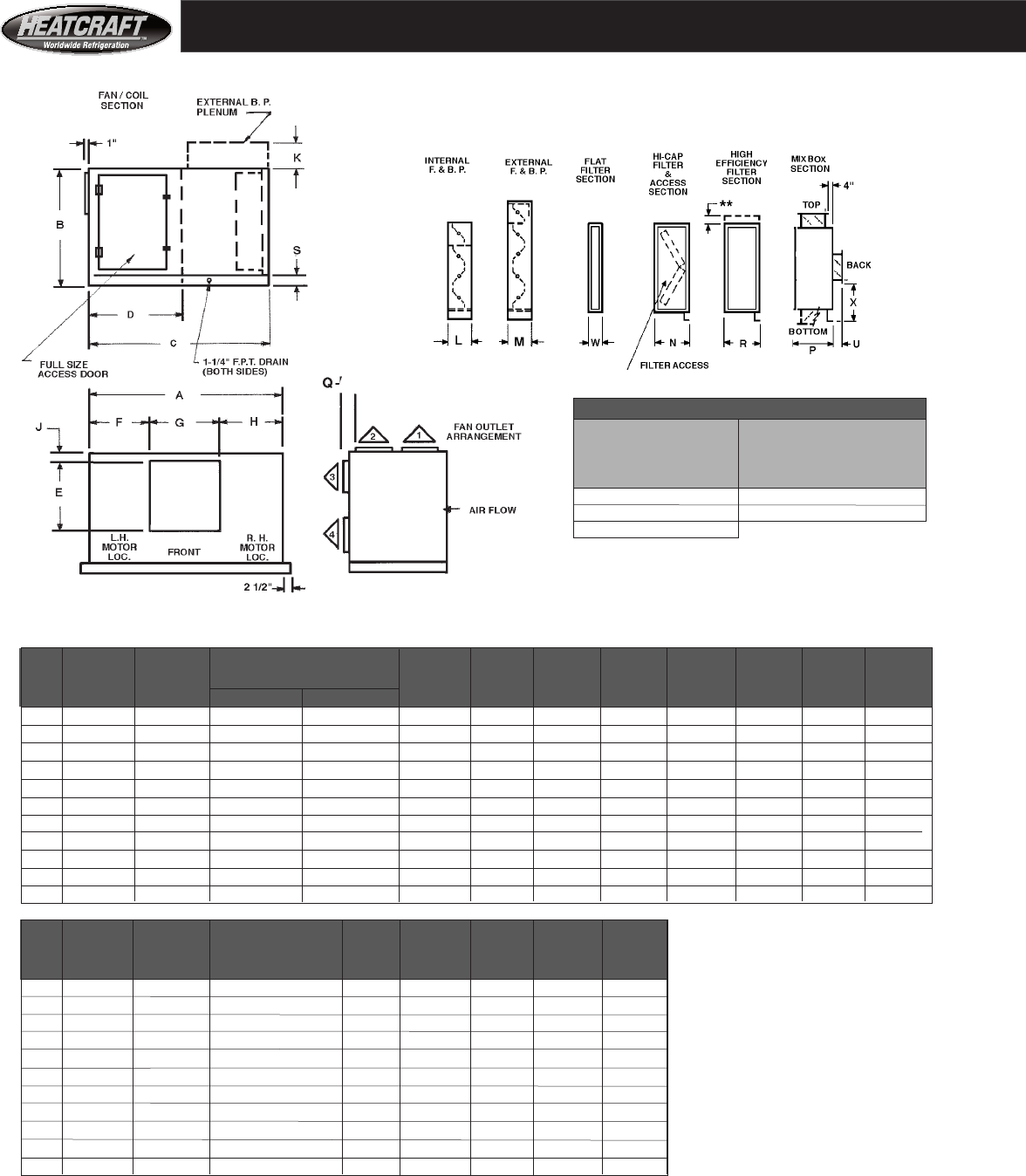
32
A B C D E F* G H* J^ K L
Unit air handler air handler air handler depth fan section fan outlet fan outlet fan outlet fan outlet discharge external internal
Size width height‘ HCS cabinet HCL cabinet depth height locator width locator arr 3 & 4 F&BP F&BP
03 39 25 1/4 45 51 7/16 — 10 1/4 18 1/8 11 7/8 9 1 1/2 6 1/4 7 3/4
06 52 28 1/2 48 1/4 54 11/16 — 13 7/16 18 3/16 15 5/8 18 3/16 1 1/2 6 1/4 7 3/4
08 49 38 57 3/4 71 — 15 7/8 17 1/8 14 3/4 17 1/8 1 1/2 10 1/4 7 3/4
10 58 38 57 3/4 71 — 18 7/8 20 5/16 17 3/8 20 5/16 1 1/2 10 1/4 7 3/4
12 64 41 1/4 61 77 1/2 — 18 7/8 23 5/16 17 3/8 23 5/16 1 1/2 10 1/4 7 3/4
14 73 41 1/4 61 77 1/2 — 24 3/4 251/8 22 3/4 25 1/8 2 1/2 10 1/4 7 3/4
18 73 50 1/4 61 77 1/2 — 24 3/4 25 1/8 22 3/4 25 1/8 2 1/2 10 1/4 7 3/4
20 90 47 66 1/4 88 5/8 44 27 1/4 31 3/8 27 1/4 31 3/8 2 10 1/4 10
26 115 47 66 1/4 88 5/8 44 27 1/4 43 7/8 27 1/4 43 7/8 2 10 1/4 10
34 115 57 74 1/4 96 5/8 52 31 1/4 41 7/8 31 1/4 41 7/8 3 13 7/16 10
41 115 68 84 1/4 106 5/8 62 36 3/4 39 1/8 36 3/4 39 1/8 4 16 5/8 10
M^^ N P Q+ S U V X Reference
Unit ext. F&BP high cap . Mix Box discharge air handler inlet inlet
Size depth filter depth without filter section arr 1 & 2 base depth height locator Motor and coil
03 8 1/2 26 1/2 20 1/2 1 1/2 2 1/2 5 1/2 4 5 1/8 connection
06 8 1/2 25 5/8 20 1/2 1 1/2 2 1/2 5 1/2 4 9 1/4 locations (R.H
08 13 28 3/4 20 1/2 1 1/2 2 1/2 5 1/2 4 14 or L.H.)
10 13 28 3/4 20 1/2 1 1/2 2 1/2 5 1/2 4 14 determined
12 14 28 3/4 20 1/2 1 1/2 2 1/2 5 1/2 4 15 5/8 facing the front
14 14 27 3/4 23 1/4 2 1/2 2 1/2 7 5 1/2 14 1/4 of the unit, with
18 14 27 3/4 23 1/4 2 1/2 2 1/2 7 5 1/2 18 3/4 the air blowing
20 15 23 23 1/4 2 3 7 5 1/2 17 3/8 through the coil,
26 15 23 23 1/4 2 3 7 5 1/2 17 3/8 and into the
34 15 23 29 3 3 7 5 1/2 19 1/2 observer’s
41 18 26 5/8 34 3/4 3 3 7 5 1/2 22 1/8 face.
For electric heat, split the coil and the fan sections on
Arrangements Available: sizes 03 through 18. For dimensions see page 6 for
Sizes 03 through 41 — Arrangements 1, 2, 3, 4. heater, page 34 for fan, and page 38 for coil section.
For All Unit Sizes
R** W
22" 6
28" 8
44"
** See page 29 for high efficiency filter section
height and width.
All dimensions above are in inches
FC = Forward Curved Fan
*Dimension “F” and “H” are for Left Hand (L.H.) drive. For Right Hand (R.H.) drive, reverse dimension “F” and “H” (Size 03 only).
+Dimension “Q” is for Discharge Arrangement 2. For Discharge Arrangement 1, “Q” measures from corresponding side of unit.
^Dimension “J” is for Discharge Arrangement 3. For Discharge Arrangement 4, Dimension “J” measures from top of base rail.
^^External face and bypass is available on HCL (long cabinet) models only.
Note: For double wall construction and internal isolation, please consult factory
* Add 6" to dim C if internal isolation and down discharge
Dimensions
Models HCS and HCL
Sizes 03 - 41 FC
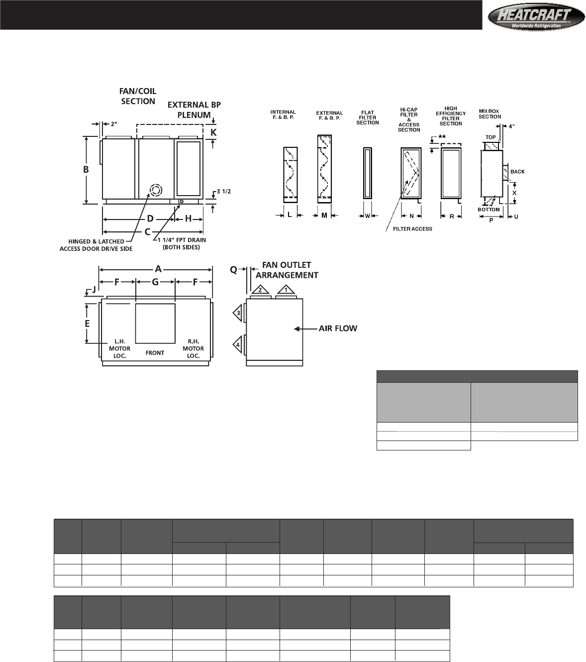
33
Models HCS and HCL
Sizes 50 - 75 AF
For All Unit Sizes
R** W
22" 6
28" 8
44"
** See page 29 for high efficiency filter section
height and width.
Dimensions
Notes:
Motor and connection locations (R.H. or L.H.) determined when facing the
front of the unit, with the air blowing through the coil and into observer’s face.
Floor or platform mounting only. Ceiling suspension is not available.
For Electric Heat : See page 6 for heater section dimensions.
Arrangements Available:
Sizes 50 through 75 — Arrangement 1, 2, 3, 4.
A B C D E F G H
Unit air handler air handler air handler depth fan section fan discharge fan discharge fan discharge coil section depth
Size width height AHS cabinet AHL cabinet depth length location width AHS cabinet AHL cabinet
50 119 78 7/8 91 109 1/4 67 3/4 34 1/2 35 9/16 47 7/8 23 1/4 41 1/2
65 135 86 7/8 98 116 1/4 74 3/4 42 1/4 38 1/2 58 23 1/4 41 1/2
75 135 98 7/8 98 116 1/4 74 3/4 42 1/4 38 1/2 58 23 1/4 41 1/2
J K L M^^ P Q+ X
Unit discharge external F&BP internal F&BP external F&BP Mixbox discharge vertical locator, back
Size arr 3 added height section depth section depth without filter section arr 1 & 2 inlet, mixbox
50 15 19 1/2 9 1/4 21 1/2 40 1/2 2 1/2 24 5/8
65 10 3/4 24 1/2 10 1/4 27 1/2 40 1/2 5 5/8 28 5/8
75 22 3/4 24 1/2 10 1/4 27 1/2 40 1/2 5 5/8 34 5/8
All dimensions are in inches.
AF = Airfoil Fan
+ Dimension “Q” is for Discharge Arrangement 2. For Discharge Arrangement 1, “Q” measures from corresponding side of unit.
^^ External face and bypass is available on HCL (long cabinet) models only.
Note: For double wall construction and internal isolation, please consult factory
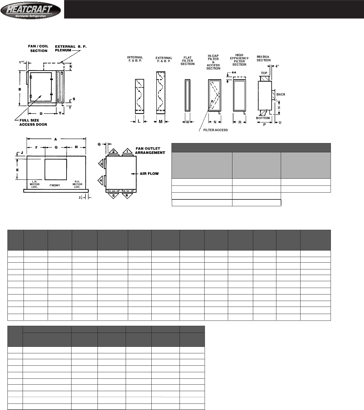
34
Models HD
Sizes 03 - 41 FC
Arrangements Available: ** See page 29 for high efficiency filter section height and width. Sizes
03 through 18 — Arrangements 1, 2, 3, 4. 5, 6.^^
Sizes 20 through 41 — Arrangements 1, 2, 3, 4.^^
Dimensions
For All Units Sizes
T R** W
1 & 2 rows 6 3/8 22 6
3 & 4 rows 10 1/8 28 8
6 rows 12 5/8 44
8 Rows 15 5/8
A B D E F* G H* J^ K L M^^ N
Unit air handler air handler fan section fan discharge fan outlet
fan discharge
fan outlet discharge ext. F&BP int. F&BP ext. F&BP high capacity
Size width height depth length locator width locator arr 3 & 4 height depth depth filter depth
03 39 25 1/4 22 3/4 10 1/4 18 1/8 11 7/8 9 1 1/2 6 1/4 7 3/4 8 1/2 26 1/2
06 52 28 1/2 26 13 7/16 18 3/16 15 5/8 18 3/16 1 1/2 6 1/4 7 3/4 8 1/2 25 5/8
08 49 38 35 1/2 15 7/8 17 1/8 14 3/4 17 1/8 1 1/2 10 1/4 7 3/4 13 28 3/4
10 58 38 35 1/2 18 7/8 20 5/16 17 3/8 20 5/16 1 1/2 10 1/4 7 3/4 13 28 3/4
12 64 41 1/4 38 3/4 18 7/8 23 5/16 17 3/8 23 5/16 1 1/2 10 1/4 7 3/4 14 28 3/4
14 73 41 1/4 38 3/4 24 3/4 25 1/8 22 3/4 25 1/8 2 1/2 10 1/4 7 3/4 14 27 3/4
18 73 50 1/4 38 3/4 24 3/4 25 1/8 22 3/4 25 1/8 2 1/2 10 1/4 7 3/4 14 27 3/4
20 90 47 44 27 1/4 31 3/8 27 1/4 31 3/8 2 10 1/4 10 15 23
26 115 47 44 27 1/4 43 7/8 27 1/4 43 7/8 2 10 1/4 10 15 23
34 115 57 52 31 1/4 41 7/8 31 1/4 41 7/8 3 13 7/16 10 15 23
41 115 68 62 36 3/4 39 1/8 36 3/4 39 1/8 4 16 5/8 10 18 26 5/8
P Q+ S U V X Reference
Unit Mixbox discharge air handler inlet inlet inlet Motor and coil connection
Size arr 1&2 base height depth height locator locations (R.H or L.H.)
03 20 1/2 1 1/2 2 1/2 5 1/2 4 5 1/8 determined facing the front
06 20 1/2 1 1/2 2 1/2 5 1/2 4 9 1/4 of the unit, with the air
08 20 1/2 1 1/2 2 1/2 5 1/2 4 14 into observer’s face.
12 20 1/2 1 1/2 2 1/2 5 1/2 4 15 5/8
14 23 1/4 2 1/2 2 1/2 7 5 1/2 14 1/4 HD Note
18 23 1/4 2 1/2 2 1/2 7 5 1/2 18 3/4 Air handler
20 23 1/4 2 3 7 5 1/2 17 3/8 depth is dimension ‘D’. HD
26 23 1/4 2 3 7 5 1/2 17 3/8 (heating duty) unit depth is
34 29 3 3 7 5 1/2 19 1/2 dimension ‘D’ added to
41 34 3/4 3 3 7 5 1/2 22 1/8 dimension ‘T’.
FC = Forward Curve Fan
*Dimension “F” and “H” are for Left Hand (L.H.) drive. For Right Hand (R.H.) drive, reverse dimension “F” and “H” (Size 03 only).
+Dimension “Q” is for Discharge Arrangement 2. For Discharge Arrangement 1, “Q” measures from corresponding side of unit.
^Dimension “J” is for Discharge Arrangement 3. For Discharge Arrangement 4, Dimension “J” measures from top of base rail.
^^Arrangements 1 & 2 are not available with external face and bypass dampers.
Note: For double wall construction and internal isolation, please consult factory
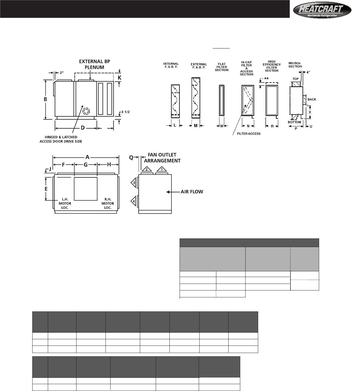
35
MODELS HD
Sizes 50 - 65 AF
T
Dimensions
Notes:
Motor and connection locations (R.H. or L.H.) For All Units Sizes
determined when facing the front of the unit, with the T R** W
air blowing through the coil and into observer’s face.
Floor or platform mounting only.
Ceiling suspension is not available. 1 & 2 rows 6 3/8 22 6
Electric Heat: See page 6 for heater section dimensions. 3 & 4 rows 10 1/8 28
6 rows 12 5/8 44 8
8 Rows 15 5/8
Arrangements Available:
Size 50 through 75 — Arrangements 1, 2, 3, 4^^
A B E F G J K
Unit air handler air handler fan discharge fan discharge fan discharge discharge external F&BP
Size width height length location width arrangement 3 added height HD Note
50 119 78 7/8 34 1/2 35 9/16 47 7/8 15 19 1/2
65 135 86 7/8 42 1/4 38 1/2 58 10 3/4 24 1/2 HD
75 135 98 7/8 42 1/4 38 1/2 58 22 3/4 24 1/2 HF(heating duty) unit
depth is dimension
L M^^ P Q+ X ‘D’ added to
Unit internal F&BP external F&BP Mixnoc discharge vertical locator, back dimension ‘T’.
Size section depth section depth arrangement 1 & 2 inlet, economizer
50 9 1/4 21 1/2 40 1/2 2 1/2 24 5/8
65 10 1/4 27 1/2 40 1/2 5 5/8 28 5/8
All dimensions are in inches.
AF = Airfoil Fan
+ Dimension “Q” is for Discharge Arrangement 2. For Discharge Arrangement 1, “Q” measures from corresponding side of unit.
^^ Arrangements 1 and 2 are not available with external face and bypass damper section.
Note: For double wall construction and internal isolation, please consult factory
** See page 29 for high efficiency filter section height and width.
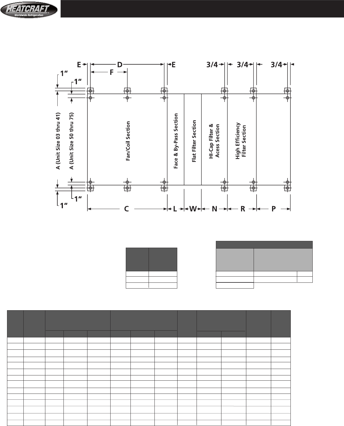
36
A* C D F L N P
air handler air handler air handler inter- face and bypass dampers high Mixbox
UNIT centers overall edge to edge depth extreme center to center depth mediate section, overall depth capacity filter
SIZE width HCS HCL VCS HCS HCL VCS center internal external or access
03 40 45 51 7/16 28 11/16 43 1/2 49 15/16 27 3/16 —— 7 3/4 8 1/2 26 1/2 20 1/2
06 55 48 1/4 54 11/16 28 11/16 46 3/4 53 3/16 27 3/16 —— 7 3/4 8 1/2 25 5/8 20 1/2
08 52 57 3/4 71 35 1/2 56 1/4 69 1/2 34 —— 7 3/4 13 28 3/4 20 1/2
10 61 57 3/4 71 35 1/2 56 1/4 69 1/2 34 —— 7 3/4 13 28 3/4 20 1/2
12 67 61 77 1/2 38 3/4 59 1/2 76 37 1/4 —— 7 3/4 14 28 3/4 20 1/2
14 76 61 77 1/2 38 3/4 59 1/2 76 37 1/4 —— 7 3/4 14 27 3/4 23 1/4
18 76 61 77 1/2 38 3/4 59 1/2 76 37 1/4 —— 7 3/4 14 27 3/4 23 1/4
20 93 66 1/4 88 5/8 44 62 1/4 88 5/8 42 40 10 15 23 23 1/4
26 118 66 1/4 88 5/8 44 62 1/4 88 5/8 42 40 10 15 23 23 1/4
34 118 74 1/4 96 5/8 52 72 1/4 94 5/8 50 50 10 15 23 29
41 118 84 1/4 106 5/8 62 82 1/4 104 5/8 60 60 10 18 26 5/8 34 3/4
50 115 3/4 91 109 1/4 —— 89 107 1/4 —— 65 3/4 9 1/4 21 1/2 30 40 1/2
65 131 3/4 98 116 1/4 —— 96 114 1/4 —— 72 3/4 10 1/4 27 1/2 30 40 1/2
75 131 3/4 98 —— 96 —— 72 3/4 10 1/4 27 1/2 30 40 1/2
All dimensions are in inches.
Mixbox Section
Dimensions
For All Unit Sizes
All mounting holes are : 5/8 inch diameter. E R W
Unit center to High Flat
Size edge Efficiency Filter Filter Section
dimension Section Depths Depths
03 - 18 3/4 22 2 inch filters 6
20 - 41 1 28 4 inch filters 8
50 - 75 1 44
Models HCS, HCL and VCS
Sizes 03 - 75
Mounting Locations For Vibration Isolators
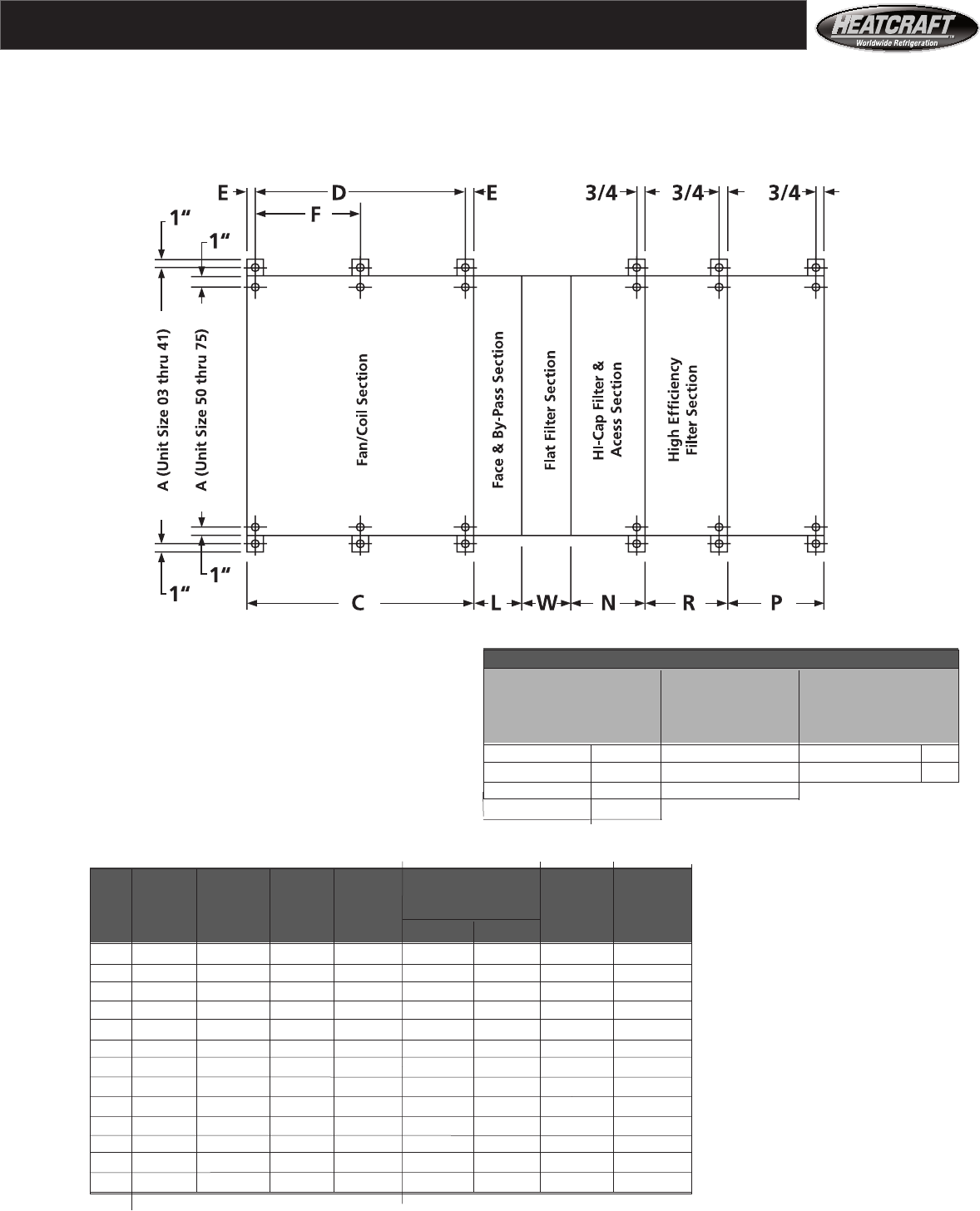
37
All dimensions are in inches.
Mixbox Section
Dimensions
Models HD
Sizes 03 - 65
Mounting Locations For Vibration Isolators
For All Unit Sizes
All mounting holes are : 5/8 inch diameter. T** R W
1 & 2 rows** 6 3/8 22 2 inch filters 6
3 & 4 rows 10 1/8 28 4 inch filters 8
6 rows 12 5/8 44
8 Rows 15 5/8
** One and two row heating coils do not have support legs.
A* C D E L N P
air handler fan section fan section center face and bypass dampers high
Unit centers edge to centers to edge section, overall depth capacity Mixbox Section
Size width edge depth depth dimension internal external or access
03 40 22 3/4 22 1/4 3/4 7 3/4 8 1/2 26 1/2 20 1/2
06 55 26 24 1/2 3/4 7 3/4 8 1/2 25 5/8 20 1/2
08 52 35 1/2 34 3/4 7 3/4 13 28 3/4 20 1/2 Note:
10 61 35 1/2 34 3/4 7 3/4 13 28 3/4 20 1/2 HD
12 67 38 3/4 37 1/4 3/4 7 3/4 14 28 3/4 20 1/2 (heating duty)
14 76 38 3/4 37 1/4 3/4 7 3/4 14 27 3/4 23 1/4 unit depth is
18 76 38 3/4 37 1/4 3/4 7 3/4 14 27 3/4 23 1/4 dimension ‘D’
20 93 44 42 1 10 15 23 23 1/4 added to the
26 118 44 42 1 10 15 23 23 1/4 AHD heating
34 118 52 50 1 10 15 23 29 section depth
41 118 62 60 1 10 18 26 5/8 34 3/4 dimension ‘T**’
50 115 3/4 67 3/4 65 3/4 1 9 1/4 21 1/2 30 40 1/2 in the table
65 131 3/4 74 3/4 72 3/4 1 10 1/4 27 1/2 30 40 1/2 above.
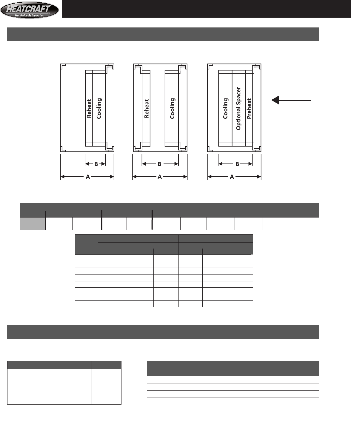
38
Models Models Models
HCS - HCL- VCS HCS - HCL HCS - HCL - VCS
Air
Flow
Dimensions
Order either rubber in shear (RIS) or 1" deflection spring isolators as accessories. Isolators are shipped loose, see
pages 36 and 37 for isolator location points, see page 3 for ceiling versus platform mounting per unit size:
Cabinet types Unit size Quantity Accessory sections (All sizes): Quantity
HCS or HCL models 03 - 18 4 required
HCS or HCL models 20 - 75 6 High capacity filter section 2
VCS models 03 - 41 4 Economizer section, combined with filters or without filters 2
HD models 03 - 75 4 Access section 2
Auxiliary coil section (either HCS or HCL ) 4
Electric preheat section 2
High efficiency filter section 2
Reheat Position Reheat Position Preheat Position
Coil Casing Depth - Inches
Type Hot Water & Steam RHR & DX RHR, DX, Water
Rows 1 2 1 2 3 4 5 6 8 10
Depth 3 1/4 3 1/4 7 7 7 7 9 3/4 9 3/4 12 1/2 15
Overall Section Depth Maximum Coil Space
Unit A B
Size HCS HCL VCS HCS HCL VCS
03-06 22 1/4 28 11/16 28 11/16 15 1/2 21 18 3/4
08-10 22 1/4 35 1/2 35 1/2 15 1/2 28 18 3/4
12-18 22 1/4 38 3/4 38 3/4 15 1/2 31 18 3/4
20 22 1/4 44 5/8 42 1/8 15 1/2 37 18 3/4
26 22 1/4 44 5/8 44 1/8 15 1/2 37 18 3/4
34 22 1/4 44 5/8 54 1/8 15 1/2 37 18 3/4
41 22 1/4 44 5/8 62 1/8 15 1/2 37 18 3/4
50-75 23 1/4 41 1/2 — 15 1/2 33 3/4 —
All dimensions are in inches.
Vibration Isolators, Quantity Required
Coil Section
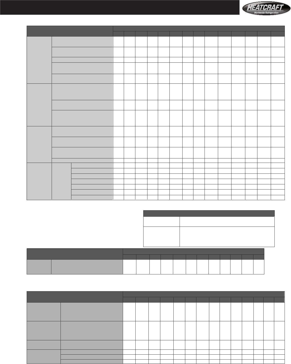
39
TA= Throw away type filters
AF= Airfoil Fan
FC= Forward Curved fan
Double wall construction add 45% to
fan & Coil section or accessory
Net Weights and Metal Gauges
Air Handler Component Unit Size
Weight in pounds 03 06 08 10 12 14 18 20 26 34 41 50 65 75
HCS short FC 290 430 500 550 650 790 816 836 968 1188 1386
Fan HCS short AF 946 1177 1518 1782 2700 3300 4496
HCL long FC 318 450 553 600 732 988 1033 1067 1221 1474 1672
and HCL long AF 1177 1430 1793 2057 2850 3480 4690
VCS vertical FC 296 387 482 535 615 860 1004 1111 1254 1628 1881
Coil HD heating duty FC 170 280 312 360 450 510 564 605 693 902 1078
HD heating duty AF 715 891 1221 1474 2600 3200 3359
Sections
Flat - TA & Pleated 2" 60 73 83 95 99 104 106 108 115 160 185 255 315 384
Flat - Permanent 2" 66 79 89 101 106 114 126 135 165 240 275 390 460 560
Filter Flat - Pleated 4" 75 88 98 110 119 124 126 127 130 185 210 298 351 428
High Capacity - TA & Pleated 149 168 187 206 215 224 230 234 244 260 290 360 440 535
Sections High Capacity - Permanent 155 176 196 216 225 234 240 244 254 365 450 520 650 790
High Efficiency - 22" Section 82 95 112 133 133 153 175 180 194 235 248 269 330 359
High Efficiency - 28" Section 103 121 143 170 170 196 225 224 246 296 318 345 425 463
High Efficiency - 44" Section 127 150 173 201 201 230 264 274 299 358 380 412 516 552
Mixbox 174 195 216 224 236 247 254 260 300 430 550 680 800 975
Other
Accessory Internal Face and Bypass 52 68 79 100 115 138 148 155 180 260 350 420 520 634
Sections External Face and Bypass 57 75 87 110 128 155 166 175 200 286 385 462 650 793
Auxiliary Coil Module HCS 129 164 204 208 223 306 280 261 310 331 362 515 640 1305
Auxillary Coil Module HCL 157 184 257 258 305 504 497 492 563 617 648 665 820 1499
Electric Heater 199 218 237 266 285 294 310 314 324 355 390 485 590 685
1 Row 36 55 70 80 94 106 110 112 144 195 239 339 406 538
2 Row 50 80 101 120 143 164 169 173 228 318 396 562 673 891
Large Type 5 3 Row 64 106 134 161 195 223 231 236 314 444 557 737 936 1168
4 Row 78 132 168 202 246 282 292 299 398 569 718 913 1199 1445
Coils 10 FPI 6 Row 109 187 240 290 353 408 422 432 578 830 1052 1278 1677 2017
8 Row 141 242 311 379 461 534 552 565 760 1092 1385 1638 2154 2589
10 Row 172 297 383 467 569 659 682 699 942 1355 1718 2194 2893 3478
(Coil weights include the weight of water when filled)
To estimate weights for other coils:
For Type A: multiply type 5 coil weight by 0.800
For Small coil : multiply large coil weight by 0.823
For 14 FPI: multiply 10 FPI coil weight by 1.121
For 12 FPI: multiply 10 FPI coil weight by 1.065
For 8 FPI: multiply 10 FPI coil weight by 0.935
For 6 FPI: multiply 10 FPI coil weight by 0.915
Air Handler Motor And Drive Motor Horsepower, 1800 RPM
Weight in pounds 1 1.5 -2 3 5 7.5 10 15 20 25 30 40 50
Motor & High Efficiency Open Single Speed 67 74 114 127 209 216 341 384 396 427 621 623
Drive Totally Enclosed Fan Cooled (TEFC) 56 71 88 104 178 194 275 336 411 461 624 670
Weight Open 2 Speed, 2 Winding 71 97 115 160 291 267 368 356 366
Air Handler Panels And Frames Unit Size
Description, metal gauge 03 06 08 10 12 14 18 20 26 34 41 50 65 75
Frame 12 12 12 12 12 12 12 12 12 12 12 10 10 10
Fan Fan Panel 16 16 16 16 16 16 16 16 16 16 16 16 16 16
Section Side Panel 16 16 16 16 16 16 16 16 16 16 16 16 16 16
Bottom Panel 14 14 14 14 14 14 14 16 16 16 16 16 16 16
Frame 14 14 14 14 14 14 14 14 14 14 14 10 10 10
Coil Top Panel 16 16 16 16 16 16 16 16 16 16 16 16 16 16
Section Bottom Panel 14 14 14 14 14 14 14 16 16 16 16 16 16 16
Drain Panel 16 16 16 16 16 16 16 16 16 16 16 16 16 16
Accessory Filter Section Casings 16 16 16 16 16 16 16 16 16 16 16 16 16 16
Sections Economizer Casings 16 16 16 16 16 16 16 16 16 16 16 16 16 16
Damper Blades 16 16 16 16 16 16 16 16 16 16 16 16 16 16
Others Removable Panels 16 16 16 16 16 16 16 16 16 16 16 16 16 16
Base Rails 10 10 10 10 10 10 10 10 10 10 10 08 08 08
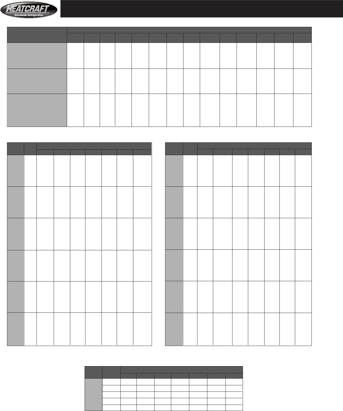
40
Face Areas- Air Pressure Drops, Dry Coils
Face Area of Coils, And Filters ( Used to Compute Velocity for Air Pressure Drop)
Face Area Air Handler Unit Size
Square Feet 03 06 08 10 12 14 18 20 26 34 41 50 65 75
Steam coils:
Large Type 5 Coils 2.75 5.28 7.50 9.38 11.69 13.75 16.88 19.25 25.50 34.00 40.38 47.25 —— ——
Large Type 8 Coils —— —— —— —— —— —— —— —— —— —— —— —— 62.00 72.33
Water & Refrigerant:
Large Type A Coils 3.13 5.76 7.81 9.77 12.40 14.58 17.71 20.05 26.56 33.65 40.73 50.63 64.58 75.35
Large Type 5 Coils 3.00 5.69 7.50 9.38 11.69 13.75 14.58 16.71 25.50 34.00 40.38 49.50 64.58 74.92
Filter Face Area:
Flat Filter Sections 5.00 6.94 10.00 11.11 15.00 17.50 22.50 24.44 31.11 38.89 46.67 54.40 73.33 82.50
High Capacity Sections 10.00 13.89 16.67 19.44 22.22 25.00 37.50 31.94 40.28 64.44 80.56 104.17 137.50 160.42
High Efficiency Section 6.00 8.00 12.00 14.00 14.00 18.00 24.00 24.00 30.00 40.00 50.00 60.00 66.00 88.00
Type 8 (1" O.D.) Dry Coil Air Pressure Drop*
Rows Fin Air Velocity^ - Feet per minute
400 450 500 550 600 650 700
6 0.05 0.06 0.07 0.09 0.10 0.11 0.13
8 0.07 0.08 0.10 0.12 0.13 0.15 0.17
1 10 0.09 0.11 0.12 0.14 0.16 0.19 0.21
12 0.10 0.13 0.15 0.17 0.20 0.22 0.25
14 0.12 0.15 0.17 0.20 0.23 0.26 0.29
* Dry coil air pressure drop for air entering at 70 °F DB, 0 °F WB over rippled high efficiency fins. Inches of water.
^ Air velocity = CFM divided by coil face area in square feet. See table at top of page 40.
Type A (1/2" O.D.) Dry Coil Air Pressure Drop* Type 5 (5/8" O.D.) Dry Coil Air Pressure Drop*
Rows Fins Air Velocity^ - Feet per minute Rows Fins Air Velocity^ - Feet per minute
400 450 500 550 600 650 700 400 450 500 550 600 650 700
6 0.05 0.05 0.07 0.08 0.09 0.10 0.11 6 0.07 0.09 0.11 0.13 0.15 0.17 0.20
8 0.06 0.07 0.08 0.09 0.11 0.12 0.14 8 0.09 0.11 0.13 0.16 0.18 0.21 0.24
1 10 0.07 0.08 0.10 0.11 0.13 0.15 0.17 1 10 0.11 0.13 0.16 0.18 0.21 0.25 0.28
12 0.08 0.10 0.11 0.13 0.15 0.17 0.19 12 0.12 0.15 0.18 0.21 0.24 0.28 0.31
14 0.09 0.11 0.13 0.15 0.17 0.19 0.21 14 0.14 0.17 0.20 0.23 0.27 0.31 0.35
6 0.09 0.11 0.13 0.15 0.18 0.20 0.23 6 0.13 0.17 0.20 0.24 0.28 0.32 0.37
8 0.11 0.14 0.16 0.19 0.22 0.25 0.28 8 0.17 0.21 0.25 0.29 0.34 0.39 0.44
2 10 0.14 0.16 0.19 0.23 0.26 0.29 0.33 2 10 0.20 0.24 0.29 0.34 0.40 0.45 0.52
12 0.16 0.19 0.22 0.26 0.30 0.34 0.38 12 0.23 0.28 0.33 0.39 0.45 0.51 0.58
14 0.18 0.22 0.25 0.29 0.34 0.38 0.43 14 0.25 0.32 0.37 0.43 0.50 0.57 0.65
6 0.14 0.16 0.20 0.23 0.26 0.30 0.34 6 0.20 0.25 0.30 0.36 0.42 0.48 0.55
8 0.17 0.21 0.24 0.28 0.33 0.37 0.42 8 0.25 0.31 0.37 0.44 0.51 0.59 0.67
3 10 0.20 0.25 0.29 0.34 0.39 0.44 0.50 3 10 0.30 0.36 0.43 0.51 0.59 0.68 0.77
12 0.24 0.29 0.34 0.39 0.45 0.51 0.57 12 0.34 0.41 0.50 0.58 0.67 0.77 0.87
14 0.27 0.32 0.38 0.44 0.50 0.57 0.64 14 0.38 0.46 0.55 0.65 0.75 0.86 0.97
6 0.18 0.22 0.26 0.31 0.35 0.40 0.46 6 0.27 0.33 0.40 0.48 0.56 0.65 0.74
8 0.23 0.27 0.33 0.38 0.44 0.50 0.56 8 0.33 0.41 0.49 0.58 0.68 0.78 0.89
4 10 0.27 0.33 0.39 0.45 0.52 0.59 0.66 4 10 0.39 0.48 0.58 0.68 0.79 0.91 1.03
12 0.32 0.38 0.45 0.52 0.60 0.68 0.76 12 0.45 0.55 0.66 0.78 0.90 1.03 1.16
14 0.36 0.43 0.51 0.59 0.67 0.76 0.85 14 0.51 0.62 0.74 0.87 1.00 1.14 1.29
6 0.27 0.33 0.39 0.46 0.53 0.60 0.68 6 0.40 0.50 0.60 0.72 0.84 0.97 1.11
8 0.34 0.41 0.49 0.57 0.66 0.75 0.84 8 0.50 0.62 0.74 0.87 1.02 1.17 1.33
6 10 0.41 0.49 0.58 0.68 0.78 0.88 0.99 6 10 0.59 0.72 0.87 1.02 1.19 1.36 1.55
12 0.47 0.57 0.67 0.78 0.89 1.01 1.14 12 0.68 0.83 0.99 1.16 1.35 1.54 1.75
14 0.54 0.65 0.76 0.88 1.01 1.14 1.28 14 0.76 0.93 1.11 1.30 1.50 1.71 1.94
6 0.36 0.44 0.52 0.61 0.71 0.81 0.91 6 0.54 0.67 0.80 0.96 1.12 1.29 1.47
8 0.45 0.55 0.65 0.76 0.87 0.99 1.12 8 0.67 0.82 0.99 1.17 1.36 1.56 1.78
8 10 0.54 0.66 0.78 0.90 1.04 1.18 1.32 8 10 0.79 0.97 1.16 1.36 1.58 1.82 2.06
12 0.63 0.76 0.90 1.04 1.19 1.35 1.52 12 0.91 1.11 1.32 1.55 1.80 2.06 2.33
14 0.72 0.86 1.02 1.18 1.35 1.52 1.71 14 1.02 1.24 1.48 1.73 2.00 2.28 2.58
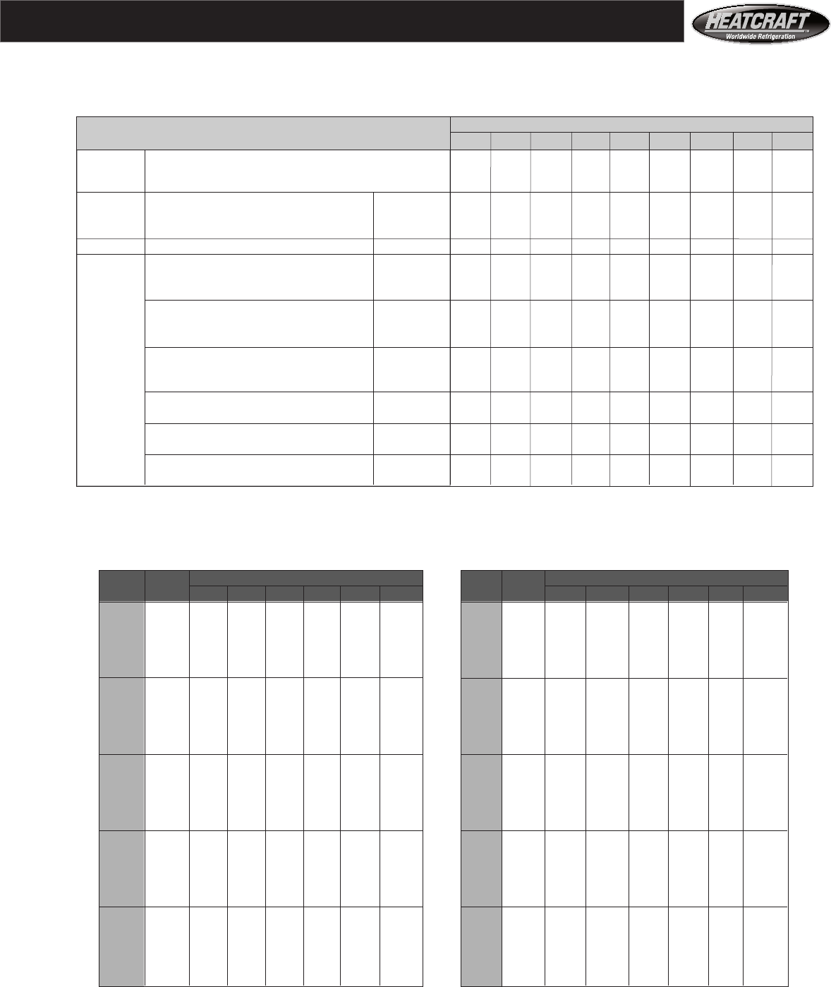
41
Air Pressure Drops- Cabinets, Filters, Wet Coils
Cabinet And Filter Air Pressure Drop
Air Pressure Drop - inches of water Air Velocity^ - Feet per minute
Component 200 250 300 350 400 450 500 550 600
Cabinet: V Style Cabinet^^ — — — .10 .13 .16 .20 .24 .29
Economizer Section^^ — — .02 .03 .03 .04 .05 .06 .07
Filters: Throwaway 2" Depth .05 .08 .11 .15 .19 .24 .28 —— ——
flat & hi 35% Efficient , Pleated 2" Depth .08 .10 .13 .16 .21 .25 .30 .37 ——
capacity Permanent, Aluminum, Cleanable 2" Depth .03 .04 .06 .08 .10 .13 .15 .18 .21
flat, 4" 35% Efficient , Pleated 4" Depth .06 .07 .10 .13 .17 .20 .25 .29 .34
(60 - 65%) Efficient 21" Depth .12 .16 .21 .26 .32 .38 .45 — —
Filters: Bag Filter 30" Depth — — .19 .24 .28 .33 .37 .41 .44
37" Depth — — .12 .17 .23 .27 .33 .37 .41
Medium (80 - 85%) Efficient 21" Depth .14 .20 .26 .32 .38 .44 .51 — —
Bag Filter 30" Depth — — .23 .28 .34 .40 .47 .51 .55
37" Depth — — .15 .21 .26 .32 .38 .45 .52
and (90 - 95%) Efficient 21" Depth .20 .28 .36 .44 .52 .61 .70 — —
Bag Filter 30" Depth — — .32 .39 .46 .53 .60 .66 .72
37" Depth — — .22 .29 .36 .44 .54 .60 .68
High (60 - 65%) Cartridge Filter 6" Depth .15 .20 .26 .33 — — — — —
12" Depth — — .22 .28 .34 .41 .50 .58 .68
(80 - 85%) Cartridge Filter 6" Depth .22 .29 .37 .46 — — — — —
Efficiency 12" Depth — — .26 .32 .38 .46 .55 .64 .74
(90 - 95%) Cartridge Filter 6" Depth .25 .34 .44 .56 — — — — —
12" Depth — — .29 .35 .42 .50 .59 .70 .82
The filter air pressure drop is for air through clean filters.
Type A (1/2" O.D.) Wet Coil Air Pressure Drop* Type 5 (5/8" O.D.) Wet Coil Air Pressure Drop*
Rows Fin Air Velocity - Feet per minute^ Rows Fin Air Velocity - Feet per minute^
Series 400 450 500 550 600 650 Series 400 450 500 550 600 650
6 0.18 0.22 0.26 0.30 0.34 0.39 6 0.25 0.30 0.36 0.42 0.49 0.56
8 0.22 0.27 0.32 0.37 0.42 0.48 8 0.31 0.37 0.44 0.52 0.60 0.68
3 10 0.26 0.32 0.37 0.43 0.50 0.56 3 10 0.36 0.44 0.52 0.58 0.67 0.79
12 0.30 0.37 0.43 0.50 0.57 0.65 12 0.42 0.50 0.59 0.66 0.76 0.87
14 0.34 0.41 0.49 0.56 0.64 0.73 14 0.45 0.54 0.64 0.74 0.85 0.97
6 0.24 0.29 0.35 0.40 0.47 0.53 6 0.33 0.40 0.48 0.56 0.65 0.74
8 0.30 0.36 0.43 0.50 0.57 0.65 8 0.41 0.50 0.59 0.69 0.80 0.91
4 10 0.35 0.43 0.51 0.59 0.67 0.77 4 10 0.48 0.58 0.69 0.81 0.93 1.06
12 0.41 0.49 0.58 0.68 0.77 0.88 12 0.56 0.67 0.79 0.92 1.02 1.20
14 0.46 0.56 0.66 0.76 0.87 0.99 14 0.63 0.75 0.89 1.03 1.14 1.34
6 0.31 0.38 0.45 0.53 0.61 0.70 6 0.41 0.50 0.60 0.70 0.81 0.93
8 0.39 0.47 0.56 0.65 0.74 0.84 8 0.51 0.62 0.74 0.86 0.99 1.13
5 10 0.46 0.55 0.65 0.75 0.86 0.97 5 10 0.60 0.73 0.87 1.01 1.12 1.32
12 0.53 0.63 0.74 0.85 0.97 1.10 12 0.69 0.84 0.99 1.11 1.27 1.50
14 0.59 0.71 0.83 0.95 1.09 1.22 14 0.78 0.94 1.11 1.24 1.42 1.68
6 0.37 0.46 0.54 0.64 0.74 0.84 6 0.49 0.60 0.72 .84 0.98 1.12
8 0.46 0.56 0.67 0.78 0.90 1.03 8 0.61 0.74 0.88 1.03 1.19 1.36
6 10 0.55 0.67 0.79 0.92 1.05 1.18 6 10 0.72 0.88 1.04 1.21 1.40 1.59
12 0.63 0.77 0.90 1.04 1.19 1.34 12 0.83 1.01 1.19 1.38 1.59 1.80
14 0.72 0.86 1.01 1.17 1.33 1.49 14 0.94 1.13 1.33 1.55 1.77 2.01
6 0.51 0.62 0.74 0.87 0.99 1.12 6 0.66 0.80 0.96 1.12 1.30 1.49
8 0.63 0.77 0.90 1.05 1.20 1.35 8 0.82 0.99 1.18 1.38 1.59 1.82
8 10 0.75 0.90 1.06 1.23 1.40 1.58 8 10 0.97 1.17 1.39 1.62 1.86 2.12
12 0.86 1.03 1.21 1.40 1.59 1.79 12 1.11 1.34 1.58 1.84 2.12 2.41
14 0.96 1.15 1.35 1.56 1.78 2.01 14 1.25 1.51 1.78 2.06 2.36 2.68
* Wet coil air pressure drop for air entering at 80 °F DB and 67 °F WB over rippled high efficiency fins. Inches of water.
^ Air velocity = CFM divided by coil or filter face area in square feet. See table at top of page 40.
^^ Use face area of large coil to calculate air speed through AHV cabinet and economizer section.
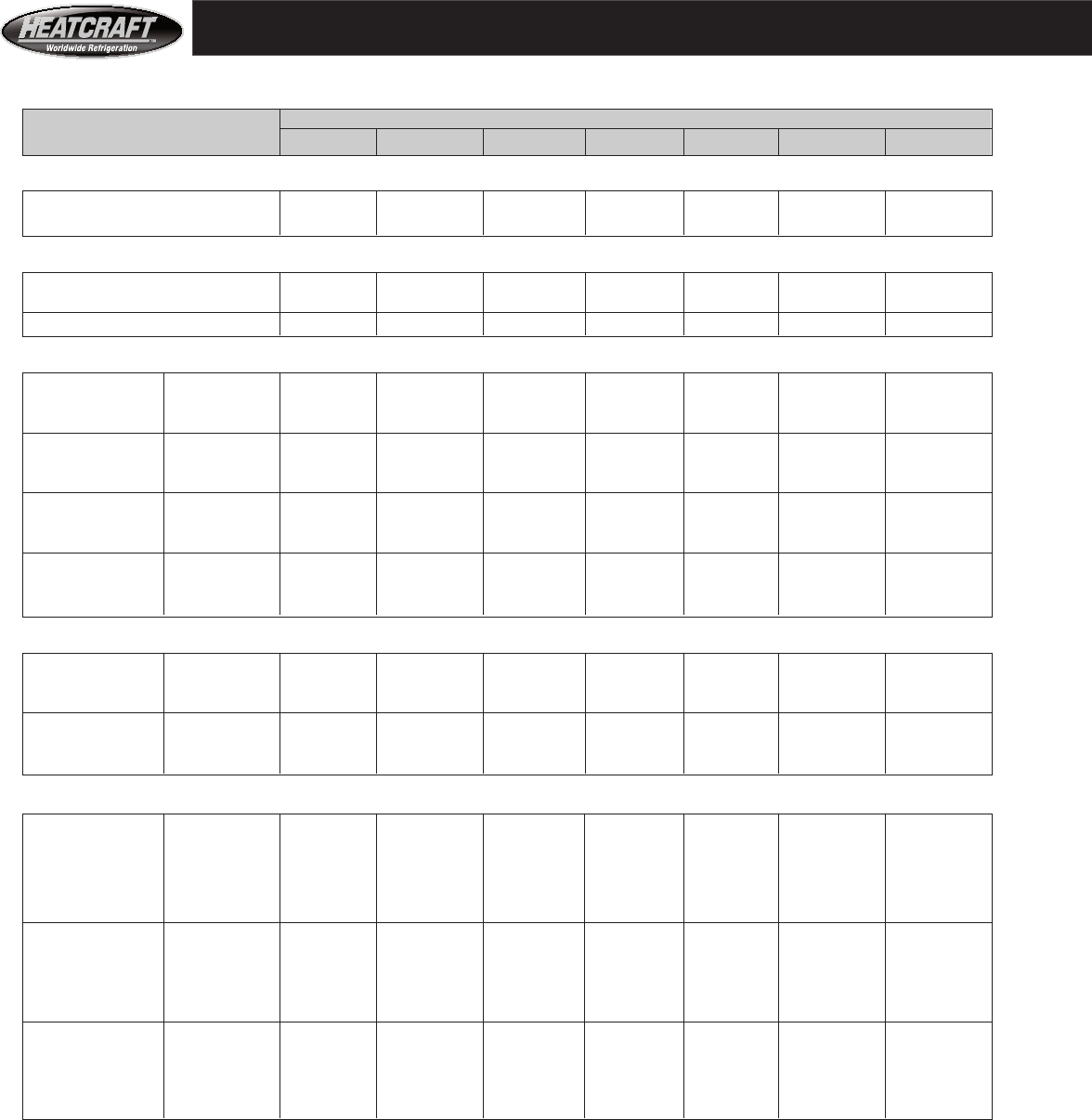
42
^ The steam coils in models 65 and 75 are not type 5. They are type 8 coils with 1" diameter tubes on 3" centers.
* The CFM range for cooling and heating starts at a low of about 400 fpm through small coil . The maximum CFM for cooling
is at no more than 550 fpm through a large coil. The maximum CFM for heating is at no more than 900 fpm through a large coil.
The fan tables are on pages 24 through 29.
Fan Type Bearings Coils Filters
FC = Forward curve fan (Ball Type) FH X FL 1-24 X 24 Means one 24" by 24 “ filter
AF = Airfoil fan C = Cartridge FH = Finned Height , inches
Shaft Diameter is inches PB = Pillow Block FL = Finned Length, inches
TH = Tubes High
FACE AREA is in Square Feet.
Refrigerant can be either direct expansion, heat reclaim , or condenser coil.
Physical Data
UNIT SIZE
Description 03 06 08 10 12 14 18
CFM Range*
Cooling 800-1650 1600-3170 2400-4100 3000-5150 3550-6400 4150-755 5800-9600
Heating & Ventilating 800-2700 1600-5000 2400-7200 3000-9200 3550-9200 4150-12400 5800-12400
Fan Type & Shaft Diameter @ Bearing
FC, Low Pres. inches 3/4—C 1—C 1—C 1—C 1—C 1 3/16 —PB 1 3/16 —PB
FC, Med. Pres. inches 1—PB 1 3/16 —PB 1 3/16 —PB 1 3/16 —PB 1 3/16 —PB 1 7/16 —PB 1 7/16 —PB
AF, shaft dia. (in) @ bearing — — — — — — —
Type 5 Coils
Large FH X FL 18.00X24 21.00X39 30.00X36 30.00X45 33.00X51 33.00X60 42.00x60
Refrigerant TH 12T 14T 20T 20T 22T 22T 28T
and Water Coils FACE AREA 3.00 5.69 7.50 9.38 11.69 13.75 17.50
Small FH X FL 12.00X24 15.00X39 24.00X36 24.00X45 27.00X51 27.00X60 36.00x60
Refrigerant TH 8T 10T 16T 16T 18T 18T 24T
and Water Coils FACE AREA 2.00 4.06 6.00 7.50 9.56 11.25 15.00
Large Type 5 FH X FL 16.50X24 19.50X39 28.50X36 28.50X45 33.00X51 33.00X60 40.50x60
Steam Coils^ TH 11T 13T 19T 19T 22T 22T 27T
FACE AREA 2.75 5.28 7.13 8.91 11.69 13.75 16.88
Small Type 5 FH X FL 12.00X24 15.00X39 24.00X36 24.00X45 24.00X51 27.00X60 34.50x60
Steam Coils^ TH 8T 10T 16T 16T 18T 18T 23T
FACE AREA 2.00 4.06 6.00 7.50 9.56 11.25 14.38
Type A Coils
Large FH X FL 18.75x24 21.25x39 31.25x36 31.25x45 35.00x51 35.00x60 42.50x60
Refrigerant TH 15T 17T 25T 25T 28T 28T 34T
and Water Coils FACE AREA 3.13 5.76 7.81 9.77 12.40 14.58 17.71
Small FH X FL 12.50X24 16.25X39 25.00X36 25.00X45 28.75X51 28.75X60 35.00X60
Refrigerant TH 10T 13T 20T 20T 23T 23T 28T
and Water Coils FACE AREA 2.08 4.40 6.25 7.81 10.18 11.99 14.58
Filters:
Area in Sq. Ft. 5.00 6.94 10.00 11.11 15.00 17.50 22.50
Flat 2-16 X 25 2-16 X 25
Section 1-16 X 20 2-16 X 20
Quantity and 1-20 X 20 2- 20 X 25 2-16 X 20 4-16 X 25 3-16 X 20 2- 20 X 25 2-20 X 25
size 1-20 X 16 2-16 X 25 3- 20X 20 1-20 X 20 2-20 X 20
High Area in Sq. Ft. 10.00 13.89 16.67 19.44 22.22 25.00 37.50
Capacity
Section Quantity and 2-20 X 20 4- 20 X 25 6-16 X 25 2-16 X 25 8-16 X 25 4-16 X 25 6-16 X 25
size 2-16 X 20 4-20 X 25 4-20 X 25 6-20 X 25
High Area in Sq. Ft. 6.00 8.00 12.00 14.00 14.00 18.00 24.00
Efficiency
Filter Quantity and 1-24 X 24 2-24 X 24 2-24 X 24 2-24 X 24 2-24 X 24 3-24 X 24 6-24 X 24
Section size 1-12 X 24 2-12 X 24 3-12 X 24 3-12 X 24 3-12 X 24
43
^ The steam coils in models 65 and 75 are not type 5. They are type 8 coils with 1" diameter tubes on 3" centers.
* The CFM range for cooling and heating starts at a low of about 400 fpm through small coil.
The maximum CFM for cooling is at no more than 550 fpm through a large coil. The maximum CFM for heating
is at no more than 900 fpm through a large coil. The fan tables are on pages 24 through 29.
Fan Type Bearings Coils Filters
FC = Forward curve fan (Ball Type) FH X FL 1-24 X 24 Means one 24" by 24 “ filter
AF = Airfoil fan C = Cartridge FH = Finned Height , inches
Shaft Diameter is inches PB = Pillow Block FL = Finned Length, inches
TH = Tubes High
FACE AREA is in Square Feet.
Refrigerant can be either direct expansion, heat reclaim , or condenser coil.
Unit Size
Description 20 26 34 41 50 65 75
CFM Range*
Cooling 6400-10600 8500-14000 10600-18500 13400-22200 17100-26800 22400-35500 25800-41200
Heating & Ventilating 6400-19000 8500-19000 10600-24000 13400-32000 17100-31000 22400-43000 25800-43000
Fan Type & Shaft Diameter @ Bearing
FC, Low Pres. inches — — — — — — —
FC, Med. Pres. inches 1 7/16—PB 1 7/16—PB 1 11/16—PB 1 15/16—PB — — —
AF, shaft dia. (in) @ bearing 1 7/16—PB 1 7/16—PB 1 11/16—PB 2 3/16—PB 2 7/16—PB 2 11/16—PB 2 11/16—PB
Type 5 Coils
Large FH X FL 36.00X77 36.00X10² 48.00X10² 57.00X10² 66.00X10⁸ 75.00X124 87.00X124
Refrigerant TH 24T 24T 32T 38T 44T 50T 58T
and Water Coils FACE AREA 19.25 25.50 34.00 40.38 49.50 64.58 74.91
Small FH X FL 30.00X77 30.00X10² 39.00X10² 45.00X10² 54.00X10⁸ 60.00X124 69.00X124
Refrigerant TH 20T 20T 26T 30T 36T 40T 46T
and Water Coils FACE AREA 16.04 21.25 27.63 31.88 40.50 51.67 59.42
Large Type 5 FH X FL 36X77 36X102 48X102 57.0X10² 63.0X10⁸ 72.0X124^ 84.0X124^
Steam Coils^ TH 24T 24T 32T 38T 42T 24T 28T
FACE AREA 19.25 25.50 34.00 40.38 47.25 62.00 72.33
Small Type 5 FH X FL 28.5X77 28.5X10² 37.5X10² 43.5X10² 51X108 60X124^ 66X124^
Steam Coils^ TH 19T 19T 25T 29T 34T 20T 22T
FACE AREA 12.84 20.19 26.56 30.81 38.25 51.67 56.83
Type A Coils
Large FH X FL 37.50X77 37.50X10² 47.50X10² 57.50X10² 67.5X10⁸ 75X124 87.5X124
Refrigerant TH 30T 30T 38T 46T 54T 60T 70T
and Water Coils FACE AREA 20.05 26.56 33.65 40.73 50.63 64.58 75.35
Small FH X FL 30X77 30X102 37.5X10² 45X102 55X108 60X124 70X124
Refrigerant TH 24T 24T 30T 36T 44T 48T 56T
and Water Coils FACE AREA 16.04 21.25 26.56 31.89 41.25 51.67 60.23
Filters:
Area in Sq. Ft. 24.44 31.11 38.89 46.67 54.40 73.33 82.50
Flat 4-16 X 20
Section 4-16 X 25
Quantity and 6-16 X 20 4-16 X 20 4-16 X 25 6-16 x 20 7-16 X 20 8-16 x 20 10-20 X 20
size 4-20 X 20 8-20 X 20 8-20 X 25 12-20 x 20 14-16 X 25 20-20 x 20 10-20 X 25
High Area in Sq. Ft. 31.94 40.28 64.44 80.56 104.17 137.50 160.42
Capacity
Section Quantity and 4-16 X 25 10-20 X 25 4-16 X 20 4-16 X 25 30-20 X 25 12-16 X 25 14-16 X 25
size 6-20 X 25 2-16 X 25 20-20 X 20 20-20 X 25 30-20 X 25 35-20 X 25
High Area in Sq. Ft. 24.00 30.00 40.00 50.00 60.00 66.00 88.00
Efficiency
Filter Quantity and 4-24 X 24 5-24 X 24 10-24 X 24 10-24 X 24 15-24 X 24 15-24 X 24 20-24 X 24
Section size 4-12 X 24 5-12 X 24 5-12 X 24 3-12 X 24 4-12 X 24
Physical Data
Heatcraft Refrigeration Products, LLC
2175 West Park Place Blvd., Stone Mountain, GA 30087
P: (800) 321-1881 • www.heatcraftrpd.com
The name behind the brands you trust.
Mechanical Specification
General
Provide a air handler of sound materials construction and design. Frame mem-
bers, structural bases and all casings parts are fabricated from mill galvanized
steel. The table on page 39 specifies the metal gauge of each component. Ex-
terior panels are to be a minimum of 16 gauge galvanized steel. Access doors
in the fan section provide complete access to motor(s), belts, drive(s) and fan.
Removable casing panels in the coil section permit removal of coil from either
side. Fan housings extend from the fan section panel for duct connections.
Air Conditioning Models - VCS, HCS, HCL
Provide a air conditioning air handler to meet cooling and condensate require-
ments. The air handler shall have standard insulation in both the fan and cool-
ing coil sections with a drain pan as described below.
Cooling Coil Sections
Provide a air handler with a readily accessible and drainable coil section. Coil
sections have removable panels on each side. Drain pan is of double wall con-
struction with insulation sandwiched between the metal pans. Two (2) 1-1/4"
FPT drain connections are supplied. These drain connections are furnished on
each side of the drain pan on all sizes. Drain pans are #16 gauge galvanized
steel. Provide standard insulation for the cooling coil section as described
below.
Insulation
Provide the air handler with adequate insulation for air conditioning require-
ments. Standard Insulation is 1"-3/4# (1 inch thick, 3/4 lbs per cubic foot)
fiberglass. Insulation is mat faced to prevent erosion. It meets the NFPA 90
Standard for flame spread and smoke generation.
Heating And Ventilating Models - HD
Provide a air handler to meet heating or ventilating (but no cooling) duty
requirements. The standard heating unit includes 1 or 2 row heating sections.
Furnish deeper coil sections for 3, 4, or 6 row coils. Do not insulate the fan or
coil sections on these units.
Fans
Provide a air handler with fan section that meets air flow requirements. All
units have been certified as complying with ARI Standard 430. All units have a
single fan design (either forward curved or airfoil). The fans are statically and
dynamically balanced in fan section before the unit leaves the factory. Fans and
shafts operate well below the first critical speed. Fan bearings are ball bearing
type selected for 200,000 hour average life. Low pressure LF fans - Sizes 03
through 12 have lifetime lubricated, rubber mounted, cartridge bearings. Unit
sizes 14 through 75 have extended lube lines to the outside casing of the air
handler on drive side.
Coils
Provide water heating, water cooling, steam heating, and direct expansion coils
with ARI certification. All coils shall be of cartridge type, coils removable
from either side of casing. Direct expansion coils are to be aluminum ripple
corrugated plate fins on the staggered copper tubes. Fins shall have belled
collars and shall be bonded to tubes by mechanical expansion. Maximum
working pressure shall be 250 psig at 300°F. Coil shall be submerged in water
for testing. Direct expansion coils shall be provided with pressure-type brass
distributors with solder-type connections. All coils shall have a minimum of___
distributors, charged with dry air. Tubing for coils shall be copper with 1/2 or
5/8 inch outside diameters. Coils shall have suction and discharge connections
on the same end. Heatcraft coil performance data is certified as complying with
ARI Standard 410.
Filter Sections
Flat - Provide the air handler with an accessible flat filter section. Flat filter
sections for 2 and 4 inch filters are available on all sizes. Access doors are
furnished on both sides.
High Capacity - Provide the air handler with an accessible high capacity filter
section. High capacity filter sections are for 2 inch filters. High capacity filter
sections have one large door on each side.
High Efficiency - Provide the air handler with a high or a medium efficiency
filter section. Units are constructed of 16 gauge galvanized steel. Fully gasket-
ed doors are standard on each side of housing and units are fitted with positive
pressure trip lock latches that assures a tight seal. Both 2 inch prefilter and one
inch final filter tracks are extruded aluminum combined with reinforced nylon
pile seal to create a corrosion resistant seal.
Economizer Section
Provide the air handler with an economizer with inlets options at the back,
bottom, and top of the section. Economizer damper casing and blades shall be
not less than 16 U.S. gauge galvanized steel. Each blade shall be die-formed,
multi-break and not exceed 49 inches in length. Blades are to be mounted to
a single square one half inch rod, to prevent linkage slip, extending the full
length of the damper casing.
Face and Bypass Section
Dampers are opposed blade type. Shafts rotate in porous bronze bearings.
Access Section
Access sections have two hinged and latched doors, for all unit sizes. Access
sections are not insulated as standard.
Visit our website at www.heatcraftrpd.com for technical literature online.
Since product improvement is a continuing effort, we reserve the right to make changes
in specifications without notice.
