HeathCo 60WCP07TX Wireless Control Panel User Manual 598 1108 rev00
HeathCo LLC Wireless Control Panel 598 1108 rev00
HeathCo >
Users Manual
DRAFT COPY
© 2002 DESA International 598-1136-00
Plug-In Control
Panel
Model SL-6007
Features
•Operational range of up to 100 feet.
•Controls all Heath®/Zenith Remote Home™ line
of products.
•Adds programmable ON/OFF function for up to
16 channels of remote controlled products.
•UL/cUL listed power supply.
•FCC/IC tested and approved.
•12/24 Hour Digital Clock Display.
•9V battery backup to prevent program loss.
•Flash control on compatible receivers when using the Panic feature.
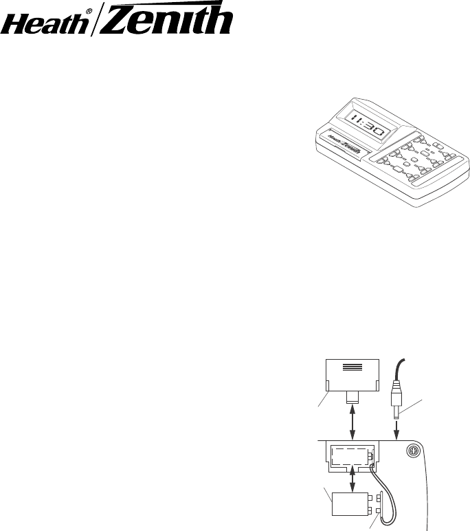
Battery Installation and Battery Backup
The SL-6007 is designed for 120VAC operation using the included DC power
converter, but has the added feature of an onboard battery backup to prevent
program memory loss. To install rechargeable battery:
1. Remove battery cover on rear of hous-
ing by sliding cover down.
2. Install rechargeable 9V battery accord-
ing to polarity markings.
3. Close battery compartment by revers-
ing the previous instructions.
Upon power failure, the battery backup will
automatically shut down all non-essential
functions. The display and keypad will not
work. The battery backup will last in excess of
5 hours. When power is restored, the unit will
restart the display and set all channels to the
OFF position. All programming will be main-
tained unless the back up reserve is de-
pleted. If the battery is depleted, reprogram-
ming of the time and automated functions will
again be required.
ON
OFF
DIM
GROUP
AB
12
MODE
ALL
ON
ALL
OFF
PAN IC
ON
OFF
DIM
ON
OFF
DIM
ON
OFF
DIM
ON
OFF
DIM
ON
OFF
DIM
ON
OFF
DIM
ON
OFF
DIM
•
••
AM
A
PM
9V Battery
Battery
Cover
DC Power
Connector
9 Volt
Battery
9 Volt Battery Connector
Installing 9 Volt Rechargable
Battery and DC Power
Connector
2
598-1136-00
DRAFT COPY
AB
ON
OFF
ON
OFF
DIM
GROUP
MODE
ALL
ON
ALL
OFF
PANIC
DIM
ON
OFF
ON
OFF
DIM DIM
ON
OFF
ON
OFF
DIM DIM
ON
OFF
ON
OFF
DIM DIM
1 2
(Dip Switch 4 in DOWN position) (Dip Switch 4 in UP position)
1 2 3
1 2 3
1 2 3
1 2 3
1 2 3
1 2 3
1 2 3
1 2 3
Setting Receiver(s) Dip Switches
The Control Panel transmitter has
preprogrammed dip switch settings for each
channel. In order for the Control Panel to
communicate with a receiver, the dip switches
on the receiver must correspond with the
preprogrammed dip switch settings of the
channel you wish to use. Note: There are no
dip switches on the Control Panel that re-
quire setting.
1. Determine which receiver(s) will be op-
erated by which channel.
2. Set receiver(s) dip switches 1, 2, and 3
to match the dip switch settings for the
channel you wish to operate the
receiver(s).
Preprogrammed Dip Switch
Settings
Channel (Includes
ON, OFF, DIM)
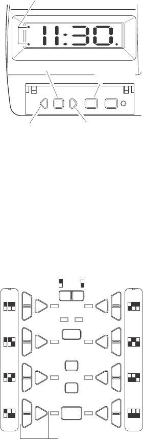
Setting The Time
The following buttons (located under the front cover) are used to set the time:
TIME SET, SELECT, and the – (LEFT) and + (RIGHT) arrow buttons.
1. Press the TIME SET button. The hour
will highlight.
2. Press the LEFT or RIGHT arrow buttons
to adjust the hour (Hint: Holding the arrow
button down will scroll through the num-
bers. Release the arrow button when the
desired hour is displayed).
Note: When in 12-hour mode the AM and
PM indicators will light indicating which
part of the day is currently selected.
3. Press the SELECT button. The minute
will highlight.
4. Press the LEFT or RIGHT arrow but-
tons to adjust the minute(Hint: Holding
the arrow button down will scroll through
the numbers. Release the arrow button when the desired hour is displayed).
5. Press the SELECT button. The 12/24-hour mode becomes adjustable.
6. Press the LEFT or RIGHT arrow buttons to toggle between 12-hour and 24-hour
display mode. Note: The AM or PM indicator will light when the 12-hour mode is
selected. If neither AM nor PM indicator is lit, the 24-hour mode is selected.
Note: If a mistake is made, return to the hour, minute, or 12/24-hour indicator at
any time by using the SELECT key to scroll to the desired position.
When the desired selections are completed, press the TIME SET button.
AM
PM A
– Select Time Set Program+
– (Left) Arrow
Setting the Time
AM/PM/24-Hour Indicators
Select Button Time Set
Button
+ (Right) Arrow
3
598-1136-00
DRAFT COPY
AM
PM A
AB
12
ON
OFF
ON
OFF
DIM
GROUP
MODE
ALL
ON
ALL
OFF
PANIC
DIM
ON
OFF
ON
OFF
DIM DIM
ON
OFF
ON
OFF
DIM DIM
ON
OFF
ON
OFF
DIM DIM
–Select Time Set Program+
AM
PM A
AB
ON
OFF
ON
OFF
DIM
GROUP
MODE
ALL
ON
ALL
OFF
PANIC
DIM
ON
OFF
ON
OFF
DIM DIM
ON
OFF
ON
OFF
DIM DIM
ON
OFF
ON
OFF
DIM DIM
– Select Time Set Program+
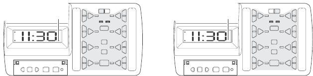
12
Group A Selected
Group Selection
Group Selection
Indicator ON
Group B Selected
Group Selection
Indicator OFF
Control Descriptions
GROUP: Allows each channel to be used for 2 different groups of receivers (for
a total of 16 channels). It also allows for the programming of 2 separate groups of
8 channels, for a total of 16 programmable (ON/OFF) combinations. To choose
Group A, press the left side of the switch (the Group Indicator will be on). To choose
Group B, press the right side of the switch (the Group Indicator will be off).
ALL ON: Turns ON all light fixtures programmed for either Group A or Group B.
Each channel LED indicator will light in sequential order as units are turned on.
To perform this function, select either Group A or Group B then press ALL ON.
If lights are off or dimmed (where applicable) they will be turned on full power.
ALL OFF: Turns OFF all light fixtures programmed for either Group A or Group
B. Each channel LED indicator will light in sequential order as units are turned
on. To perform this function, select either Group A or Group B then press ALL
OFF. If lights are on or dimmed (where applicable) they will be turned off.
PANIC: Turns ON all light fixtures programmed for either Group A or Group B.
Light fixtures within the selected group that have Flash capability will FLASH
when this command is received. Each channel LED indicator will alternately light
in sequential order. ALL OFF will turn off all channels within the selected group
and reset all light fixtures to normal operating mode.
Channel ON: Turns ON all light fixtures that are configured to work with a
particular channel. To perform this function, press the ON button located by the
channel number desired (between 1 and 8). When ON is pressed, the channel
LED will momentarily light.
Channel OFF: Turns OFF all light fixtures that are configured to work with a
particular channel. To perform this function, press the OFF button located by the
channel number desired (between 1 and 8). When OFF is pressed, the channel
LED will momentarily light.
3. Determine whether the receiver(s) will be in Group A or B.
4. Set dip switch 4 on the receiver to the same setting as Group A or B.
4
598-1136-00
DRAFT COPY
Programming Functions
MODE: Pressing the MODE button toggles between the different programmed
mode settings. The possible settings are MODE 1, MODE 2, both MODE 1 and
2, and off. When the MODE 1 LED is on, all programmed channels for MODE
1 will be activated. When the MODE 2 LED is on, all programmed channels for
MODE 2 will be activated. To activate both MODE 1 and MODE 2 programs,
press the MODE button until both LED’s are on. To turn off all programmed
channels, press the MODE button until both LED’s are off.
Program Mode: Allows the user to program ON/OFF times for selected
channels. The clock display is used to set the times for the programming modes.
The current time will not be lost during programming.
Each channel is capable of saving up to two separate ON/OFF program settings.
The possible program settings are: 2-Group A, or 2-Group B, or 1-Group A and
1-Group B.
Pushing the PROGRAM button enters the program mode and allows the user to
set up ON and OFF times for each switch (the DIM button is not available for
programming).
1. Choose Group A or B depending on which channel will be programmed.
2. Press PROGRAM button. The LED next to the PROGRAM button will light
and the Mode 1 LED will light. Note: Pressing the program button repeat-
edly will toggle modes. The sequence is Program MODE OFF, MODE 1,
MODE 2, repeat.
3. The hour display will highlight. Press the LEFT or RIGHT arrow buttons to
adjust the hour.
4. Press the SELECT button. The minute will highlight.
5. Press the LEFT or RIGHT arrow buttons to adjust the minute.
6. When the desired ON time is displayed press the ON button located by the
channel number desired (between 1 and 8). The ON time is now programmed
(the Group Indicator will Flash when the ON time has been saved).
7. Press the LEFT or RIGHT arrow buttons to adjust the minute.
8. Press the SELECT button. The hour will highlight.
9. Press the LEFT or RIGHT arrow buttons to adjust the hour.
Channel DIM: Dims all light fixtures that are equipped with the dimming feature
that are configured to work with a particular channel. To perform this function,
press the DIM button located by the channel number desired (between 1 and 8).
Pressing DIM repeatedly will toggle thru the different dim levels if the light fixture
is capable of more than one level of dim. Each time the DIM button is pressed,
the channel LED will momentarily light.
The DIM button saves the last dim setting used. To recall the last dim setting,
press the DIM channel once.
Note: The light fixture must be capable of dimming for the DIM button to work
properly.
5
598-1136-00
DRAFT COPY
AM
PM A
AB
ON
OFF
ON
OFF
DIM
GROUP
MODE
ALL
ON
ALL
OFF
PANIC
DIM
ON
OFF
ON
OFF
DIM DIM
ON
OFF
ON
OFF
DIM DIM
ON
OFF
ON
OFF
DIM DIM
–Select Time Set Program+
12
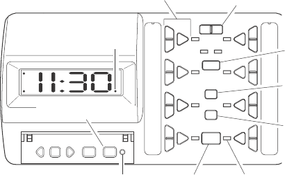
Programming Control Panel
Programming Indicator (LED)
Program Button
Group Selection
Button (A or B)
Channel (Includes
ON, OFF, DIM)
Mode Selection
Button (1 or 2)
All On
All Off
Panic Button LED Indicators
Group Selection
Indicator (LED)
10. When the desired OFF time is displayed press the OFF button located by
the same channel number as above. The OFF time is now programmed (the
Group Indicator will Flash when the OFF time has been saved).
•To save additional ON/OFF programs for other switches within the same
group and the same MODE, repeat the above steps using a different channel
for each additional program.
•To save an additional ON/OFF program for the same channel within the same
group but a different MODE, press the PROGRAM button. The LED above
Mode 2 will light. Repeat above steps to program additional ON/OFF times.
•To save an additional ON/OFF program for the same channel but using Group
B, press the PROGRAM button until the PROGRAM LED turns off. Press the
Group B button. Repeat the above steps using a different MODE setting than
the first program to set the second ON/OFF program.
•To exit PROGRAM mode, press the PROGRAM button until the LED indicator
turns off.
Note: The 12/24 hour setting can not be changed while programming channels.
•To change any programmed channel to a new ON/OFF time, repeat the
above steps for the channel you wish to change.
•To erase a programmed channel so it is not activated when a programmed
mode is selected, set both the ON and OFF times to the same setting.
To activate the programmed channels, press the MODE button to display MODE
1, MODE 2, or both MODE LED’s depending on the programmed channels you
want activated. (See MODE button description.)

6
598-1136-00
DRAFT COPY
Specifications
Range.......................................................................... Up to 100 feet (30.5 m)
Rated Voltage ........................................................................................9 VDC
Battery Backup ................................................................. 9 VDC Rechargable
POSSIBLE CAUSE
1. Circuit breaker or fuse is
turned off. Power supply
not plugged in.
2. Switch on device is turned
off. Power supply is defec-
tive.
1. Backup battery is not in-
stalled.
1. Dip switch settings on re-
ceiver do not match con-
troller.
2. Wrong group is selected.
Troubleshooting Guide
SYMPTOM
Controller does
not come on.
Controller
does not retain
settings in a
power failure.
Controller will
not operate re-
ceiver.
Technical Service
(Do Not Send Products)
If you experience a problem, follow this guide. You may also want to visit our Web
site at: www.desatech.com. If the problem persists, call* for assistance at 1-800-
858-8501, 7:30 AM to 4:30 PM CST (M-F). You may also write* to:
DESA International, Inc.
P.O. Box 90004, Bowling Green, KY 42102-9004
ATTN: Technical Service Specialty Products
* If contacting Technical Service, please have the following information avail-
able: Model Number, Date of Purchase, and Place of Purchase.
No Service Parts Available for this Product
POSSIBLE CAUSE
1. Turn circuit breaker or fuse
on. Plug in power supply.
2. Turned switch on. Try an-
other power supply.
1. Install rechargable 9V bat-
tery. Replace defective 9V
rechargable battery.
1. Check dip switch settings
on receiver.
2. Verify correct group is se-
lected.

7
598-1136-00
DRAFT COPY
YOUR HEATH®/ZENITH TWO YEAR LIMITED WARRANTY
This is a "Limited Warranty" which gives you specific legal rights. You may also have
other rights which vary from state to state or province to province.
For a period of two years from the date of purchase, any malfunction caused by
factory defective parts or workmanship will be corrected at no charge to you.
Batteries are not covered. To obtain a refund or a replacement, return the product
to the place of purchase.
Not Covered - Repair service, adjustment and calibration due to misuse, abuse or
negligence, light bulbs and other expendable items are not covered by this warranty.
Unauthorized service or modification of the product or of any furnished component
will void this warranty in its entirety. This warranty does not include reimbursement
for inconvenience, installation, setup time, loss of use, or unauthorized service.
This warranty covers only Heath®/Zenith assembled products and is not extended to
other equipment and components that a customer uses in conjunction with our products.
THIS WARRANTY IS EXPRESSLY IN LIEU OF ALL OTHER WARRANTIES,
EXPRESS OR IMPLIED, INCLUDING ANY WARRANTY, REPRESENTATION OR
CONDITION OF MERCHANT ABILITY OR THAT THE PRODUCTS ARE FIT FOR
ANY PARTICULAR PURPOSE OR USE, AND SPECIFICALLY IN LIEU OF ALL
SPECIAL, INDIRECT, INCIDENTAL, OR CONSEQUENTIAL DAMAGES.
REPAIR OR REPLACEMENT SHALL BE THE SOLE REMEDY OF THE CUS-
TOMER AND THERE SHALL BE NO LIABILITY ON THE PART OF DESA FOR ANY
SPECIAL, INDIRECT, INCIDENTAL, OR CONSEQUENTIAL DAMAGES, INCLUD-
ING BUT NOT LIMITED TO ANY LOSS OF BUSINESS OR PROFITS, WHETHER
OR NOT FORESEEABLE. Some states or provinces do not allow the exclusion or
limitation of incidental or consequential damages, so the above limitation or
exclusion may not apply to you. Retain receipt for warranty claims.
DESA International reserves the right to discontinue products and to change
specifications at any time without incurring any obligation to incorporate new
features in products previously sold.
Regulatory Information
This device complies with Part 15 of the FCC Rules and RSS-210 of Industry
Canada. Operation is subject to the following two conditions: (1) this device may
not cause harmful interference, and (2) this device must accept any interference
received, including interference that may cause undesired operation.
The term “IC:” before the radio certification number only signifies that Industry
Canada technical specifications were met.
The user is cautioned that changes or modifications not expressly approved by
the party responsible for regulatory compliance could void the user’s authority
to operate the equipment.