HeathCo WRC6005TX Wireless Lighting Remote Control User Manual 598 1108 rev00
HeathCo LLC Wireless Lighting Remote Control 598 1108 rev00
HeathCo >
Users guide
DRAFT COPY
FEATURES
•Products are UL/cUL and/or FCC/IC tested and approved.
•Operational range of up to 100 feet.
Heath®/Zenith wireless lighting controls are designed to work
together. Simply determine which transmitter(s) you would
like to have control which receiver(s) and set the code setting
to match.
•Transmitters
–Remote Control
–Add-A-Switch
–Entry Switch
–Wireless Motion Sensor
Remote Controlled Products
This manual includes operating instructions for a variety of remote controlled products. All products work on the same principle and use the
same code setting information. Please read all instructional information and note any specific information pertaining to your particular product.
WARNINGS:
•FOR USE ONLY with 120 volt incandescent or halogen bulbs.
•DO NOT USE with fluorescent bulbs, appliances, power supplies, low voltage lighting, or any other electrical devices.
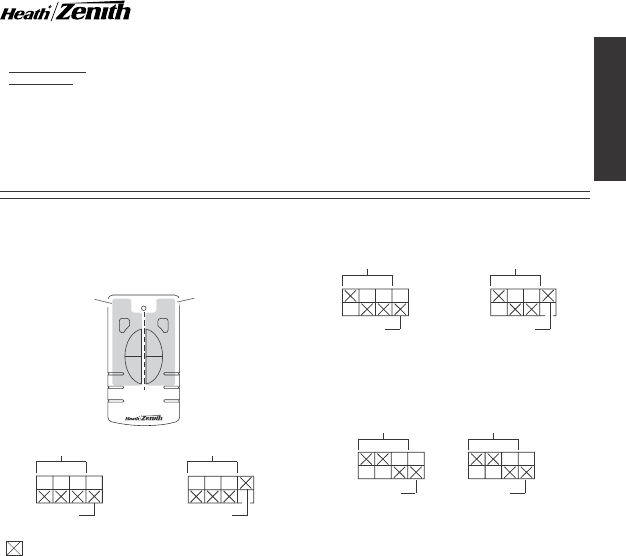
CODE SETTINGS
Note:
Most single system installations will not require any
change to the code setting. Transmitter(s) and receiver(s)
must have the same code and group setting to work to-
gether. Switches 1 through 3 set the code. Switch 4 sets the
Group (A or B). See page 2 for switch locations.
DIM
AB
ON
OFF
ON
OFF
DIM
Receiver(s)
Code
Receiver(s)
Code
Group A
Group B
Remote Motion
Sensor Code
Group A
Example 1 - Code Switch Settings, System 1
(Factory Setting)
Device A Controls:
Controls One Set of
Group “A” or Group
“B” Receiver(s)
Device B Controls:
Controls One Set of
Group “A” or Group
“B” Receiver(s)
Note:
When operating more than one system independently of
each other, set each system to a different code. There are 8 codes
available by changing the settings of switches 1 through 3.
Example 2 - Code Switch Settings, System 2
Receiver(s)
Code
Receiver(s)
Code
Group A Group B
When using a single group transmitter (
i.e.
Door Transmitter, Add-
A-Switch, Remote Motion Sensor) the code and group settings
must match receiver(s) for the system to function properly.
•Receivers
–Indoor Plug-In Converter
–Floodlight
–Lamp Socket Converter
This manual applies to the following products:
Note:
The channel can also be changed to reduce interference
problems from other wireless products (
i.e.
wireless phones,
garage door openers, etc.). See
Troubleshooting Guide
for more
information.
Receiver(s)
Code
Group A
Example 3 - Code Switch Settings with Single Transmitter
Note:
This setting will work independently of examples 1 and 2
because the code setting is different.
(– Indicates Position of Switch)
© 2004 DESA Specialty Products™ 598-1116-08
ENGLISH
2
598-1116-08
DRAFT COPY
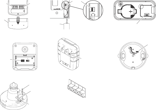
Remote Control
Indoor Plug-In Converter
CODE SWITCH LOCATIONS
ON DIP
1 2 3 4
ON DIP
1 2 3 4
Device B
Code
Switches
Battery
Cover
ON
1 2 3 4
Code
Switches
1 2 3 4
ON
2032
3
V
L
i
t
h
i
u
m
B
a
t
t
e
r
y
DIM
Add-A-Switch
Access
Door
1 2 3 4
ON
h
i
u
m
B
Entry Switch
Floodlight
Lamp Socket Converter
1 2 3 4
Code
Switches
Screw
Cover
Code
Switches
Wireless Motion Sensor
Code
Switches
DETECT
CODES
1234
DAY
NIGHT
NIGHT
ONLY
Code
Switches
ON
1 2 3 4
Close-Up of Typical Code Switch
(Factory Default Setting is Off)
Note:
The “X” has been placed on the
switches to help clarify the code
settings on the previous page.
CR2032
3 VOLTS
1 2 3 4
ON
Code Switches
Device A
Code
Switches
3
598-1116-08
ENGLISH
DRAFT COPY
Note:
One remote control is able to independently
operate two receiver units set on the same channel. If
more than two receiver units, operating independently,
are desired, additional remote controls will need to be
purchased.
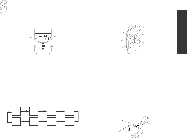
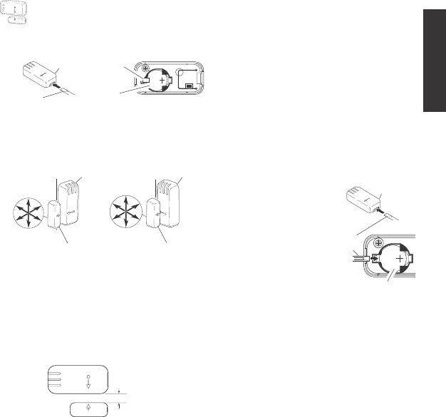
1. Remove Tab from Battery Chamber. Remove cover from
back of transmitter. Gently pull tab out of battery chamber.
Slide cover onto transmitter.
REMOTE CONTROL
2. Remote Control Functions. The three buttons on the left side
of the remote will operate one or more receiver units with
matching addresses. The three buttons on the right side of
the remote will operate a second set of one or more receiver
units.
•Device A/B ON: Turns on any receiver unit set to the same
channel as this remote control.
•Device A/B OFF: Turns off any receiver unit set to the same
channel as this remote control.
•Device A/B DIM: Activates the DIM feature for any receiver unit
set to the same channel as this remote control.
Note:
Pressing
the DIM button steps through five brightness levels.
Note:
To independently operate a second receiver unit using a
single remote control, make sure the second set of code switches
(Device B) and the code switches on each receiver match (see
Code Settings
section).
•Device A - Set Device A code switches.
•Device B - Set Device B code switches.
Rear View of Remote Control Function Controls
ON DIP
1 2 3 4
ON DIP
1 2 3 4
Battery
Chamber
(Type A23)
Battery
Cover
Tab
Device A DIM
Device A ON
Device A OFF
Device B DIM
Device B ON
Device B OFF
4543
1232
Important: Wait 1 to 2 seconds after you press a transmitter
button before you press it again to allow the transmission to be
completed.
Note:
If light does not turn on or intermittently turns on and off when
transmitter buttons are pushed, see
Troubleshooting Guide
.
Optional Car Visor Clip (Included)
The remote control includes an optional car visor clip for added
convenience that may be installed.
1. To attach car visor clip to remote control (if desired) push it
into slot on rear of remote unit until it snaps into place.
2. To remove car visor clip, insert a small, flat-head screwdriver
into slot on back of remote. Gently push down on portion of
visor clip inside slot with screwdriver while pulling clip out of
remote from top.
Removing Visor Clip - Rear View
Flat-Head
Screwdriver Optional
Visor Clip
4
598-1116-08
DRAFT COPY
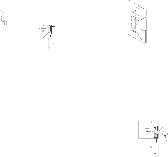
ADD-A-SWITCH
Installation
1. Remove Tab from Battery Chamber. Remove cover
from front of Add-A-Switch transmitter. Gently pull
tab out of battery chamber. Slide cover onto Add-A-
Switch transmitter.
DIM
Add-A-Switch
Add-A-Switch
ON/OFF
Button
DIM
Button
Access Door
DIM
Removing Battery Tab
1 2
ON
2032
3
V
L
i
t
h
i
u
m
B
a
t
t
e
r
y
Battery Chamber
(Type CR2032) Access Door
Tab
1 2 3 4
ON
DIM
2032
3
V
L
i
t
h
i
u
m
B
a
t
t
e
r
y
CR2032
Lithium
Battery
Battery
Locking
Tab
Access
Door
Removing Access Door
and Battery
5. Continue to press the DIM button until the desired dim level is
reached.
Note:
Receiver remembers last DIM setting used. To
recall last DIM setting, push and release the DIM button.
Note:
The DIM setting defaults to 50% in the event of a power
failure.
Important: Wait 1 to 2 seconds after you press a transmitter
button before you press it again to allow the transmission to be
completed.
Note:
If light does not turn on or intermittently turns on and off when
transmitter buttons are pushed, see
Troubleshooting Guide
.
Battery Replacement
The wall switch transmitter requires a type CR2032, 3-volt
lithium battery to operate. The transmitter is shipped with the
battery installed. With typical use, the battery will last approxi-
mately 5 years. Remove battery when transmitter will not be
used for an extended period of time.
1. Place thumb on access door and slide down to open.
2. Carefully bend locking
tab outward. Battery will
pop up.
3. Remove battery from
socket.
4. Install replacement bat-
tery in socket plus (+)
side up (see illustra-
tion). Press down on
battery until locking tab
snaps into place.
5. Reinstall access door
by sliding it upward un-
til it locks in place.
2. Select mounting location for add-a-switch transmitter.
Note:
Transmitter should be located within 100 feet (30 m) of receiver.
Note:
Transmitter should be mounted approximately 4 feet
from the floor and in the vertical position.
3. Before mounting, hold transmitter in selected location and
verify operation (see
Operation
).
Note:
If transmitter does
not operate correctly, see
Troubleshooting Guide
.
4. With transmitter held in place, mark the mounting holes with
a pencil or pointed object.
5. Remove transmitter and drill two 3/16" holes. Tap drywall
anchors (provided) into holes with a hammer.
6. Attach transmitter to wall using two screws (provided).
Operation
1. Verify that receiver has been properly installed. See
Re-
ceiver Information,
page 7.
2. Push the ON (top) button and release. The light should turn
on full bright.
3. Push the OFF (bottom) button and release. The light should
turn off.
4. Push the DIM button and release. The light should turn on at
a DIM level.
5
598-1116-08
ENGLISH
DRAFT COPY
ENTRY SWITCH
Installation
Note:
Entry system includes a transmitter and mag-
net. The system can be used to signal that a door or
window has been opened or to automatically turn the
light on when entering a closet, attic, room, etc.
1. Remove Tab from Battery Chamber. Remove transmitter
back cover from transmitter using small, flat-blade screw-
driver. Gently pull tab out of battery chamber.
Removing Battery Tab
Important Considerations:
•Entry transmitter components are for indoor use only.
•The transmitter should be mounted on the frame of door or
window (stationary surface). The magnet should be mounted
on door or window (moving surface). See illustration below for
mounting configurations and possible directions of movement.
1 2 3 4
ON
CR2032
3 VOLTS
Battery (Type
CR2032)
Transmitter Tab
Flat-Head
Screwdriver
•A compatible receiver must be used to complete the system.
The receiver should be located within 100 feet (30 m) of
transmitter (maximum distance may vary depending on type of
structures between transmitter and receiver).
2. Select mounting location for entry transmitter.
Note:
Maximum
gap between transmitter and magnet is 3/8" and the arrows
located on the face of each component must be in alignment (see
illustration). Also, the front surfaces of the transmitter and magnet
must be flush. If magnet is recessed, use magnet extension and
two long screws (provided) to ensure proper alignment.
Transmitter Mounted On Stationary Surface
Magnet Mounted On Moving Surface
Mounting Configurations and Possible Directions of
Movement
3/8" MAXIMUM
3. Before mounting, hold transmitter and magnet in selected
location and verify operation. While holding the transmitter
stationary, move the magnet away from transmitter to simu-
late door or window being opened. Verify red LED on
transmitter flashes momentarily and receiver turns light on.
Return magnet to original position simulating door or window
being closed. Verify red LED on transmitter flashes momen-
tarily and receiver turns light off.
Note:
If transmitter does not
operate correctly, see
Troubleshooting Guide
.
4. Mount Transmitter.
Screw Mounting: Attach transmitter back cover to wall using
two short screws (provided). Snap transmitter onto back
cover.
Tape Mounting: Apply large piece of foam tape (provided)
to the transmitter back cover. Stick transmitter back cover to
frame of door or window in desired position. Snap transmitter
onto back cover.
5. Repeat step 4 to attach magnet to door or window.
Battery Replacement
The entry transmitter requires a type CR2032, 3-volt lithium
battery to operate. The transmitter is shipped with the battery
installed. With typical use, the battery will last approximately five
years. Remove battery when transmitter will not be used for an
extended period of time.
1. Remove transmitter from
transmitter back cover
using small, flat-blade
screwdriver.
2. Carefully pry battery
loose with small, flat-
blade screwdriver. Bat-
tery will pop up.
3. Install replacement battery
in socket plus (+) side up
(see illustration). Press
down on battery until it
snaps into place.
4. Snap transmitter onto
back cover.
Note:
The magnet does not require a battery.
CR2032
3 VOLTS
CR2032 Lithium Battery
Flat-Blade
Screwdriver
Battery Replacement
Transmitter
Possible Directions
of Movement Possible Directions
of Movement
6
598-1116-08
DRAFT COPY
WIRELESS MOTION SENSOR
Features:
•No wiring required.
•Up to 70 feet sensing range, 180° Coverage.
•Adjustable sensitivity.
•Day/Night or Night only operation.
•Test mode.
•Uses 2 AA batteries.
•Wall or eave mount.
•Controls receivers up to 100 feet away.
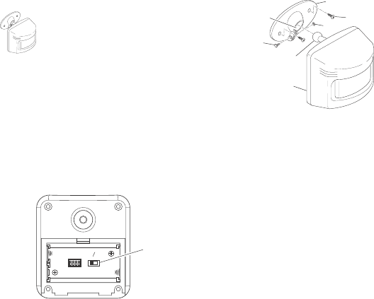
Select Night or 24 Hour Mode
This sensor is able to detect motion day and night or night only.
To set the detection mode, remove rear panel by sliding the
panel down. Remove batteries if necessary. Slide the DETECT
switch to either the DAY/NIGHT or NIGHT ONLY position.
Replace rear panel by reversing the above instructions.
Installing Batteries
Before mounting sensor, remove rear panel by sliding the panel
down. Install 2 AA batteries according to polarity markings inside
the battery compartment. Replace rear panel by reversing the
above instructions.
Installing Motion Sensor
1. Install sensor mounting bracket where motion detection is
desired. Attach sensor mounting bracket to a sturdy object
(
i.e.
tree, post, house, etc.) using two screws provided. Make
sure unit has an unobstructed view.
Note:
If mounting bracket
to a curved surface, attach mounting bracket vertically.
2. Install motion sensor to mounting bracket. Using a Philips-
head screwdriver, loosen the clamp screw on the mounting
bracket. Insert swivel ball mount on sensor into mounting
bracket socket (
Note:
You should hear a snap). Aim sensor
toward area where detection is desired. Tighten clamp screw.
IMPORTANT:
The sensor must be mounted with the bottom
cover facing down in order to maintain water tightness.
Installing Motion Sensor
Check Operation and Adjustment
Note:
When first turned on or when switching modes wait 1 1/2
minutes.
The RANGE control and ON-TIME control are located on the
bottom of the sensor. Using your fingernails or a small, flat-head
screwdriver, gently pry the cover until it opens.
1. Check Operation. Set the ON-TIME control to TEST mode.
Walk in front of sensor unit. The LED indicator light located on
the bottom of the sensor should flash when motion is detected.
2. Adjust Sensor. Turn the RANGE control to the mid position
and ON-TIME control to the TEST position. Walk through
coverage area noting where you are when the LED begins to
flash. Loosen the clamp screw and move the sensor to
change the coverage area. Tighten clamp screw when
finished. Do not overtighten clamp screw.
3. Adjust Range Control. To increase sensitivity, turn the RANGE
control toward MAX. To decrease sensitivity, turn the RANGE
control toward MIN.
Note:
If the RANGE is set too high, false
triggering may result in some environments.
Note:
When using test mode to check operation in the day time:
A. Set the DETECT control switch to DAY/NIGHT and
B. Set the ON-TIME control to TEST.
4. Set ON-TIME Control. Determine the amount of time you
want the connected device to stay on after motion is detected
(1 or 5 minutes). Slide the ON-TIME control to the corre-
sponding setting.
IMPORTANT:
Avoid Aiming Control At:
•Objects that change temperature rapidly, such as heating
vents and air conditioners. These heat sources could cause
false triggering.
•Areas where pets or traffic may trigger the control.
•Nearby large, light colored objects reflecting light may trigger
the shut-off feature. Do not point other lights at the sensor.
Mounting Bracket
Clamp
Screw
Nut
Sensor
Mounting Screw
Swivel Ball Mount
Mounting
Bracket Socket
DETECT
CODES
1234
DAY
NIGHT
NIGHT
ONLY
Detect
Control
Battery Compartment - Rear View
7
598-1116-08
ENGLISH
DRAFT COPY
RECEIVER INFORMATION
All receivers have the following features and ratings:
•Rated for 120VAC/60Hz supply voltage.
•Light can be dimmed when used with remote control (OFF, 5
Selectable Dim Levels from Dimmest to Brightest, Full On).
•Remembers last selected dim setting.
•Not for use with Compact Fluorescent bulbs.
•When first turned on wait 15 seconds.
INDOOR PLUG-IN CONVERTER
Features and Ratings:
•Up to 300 Watt maximum incandescent load.
•No wiring required.
1. Plug in indoor receiver.
2. Plug in light you wish to control.
Caution: Do not exceed the maximum load limits listed
above.
3. Check operation. Activate transmitter being used with re-
ceiver (see transmitter instructions). A signal will be sent to
the receiver to turn the receiver ON or OFF.
4. Using Remote By-Pass Switch. These receivers are equipped
with a remote by-pass switch. This switch allows the user to
select between AUTO and MANUAL modes. AUTO mode
allows the light to be operated by remote control or remote
motion sensor. MANUAL mode allows the plugged in light to
be operated manually.
5. Adjust audio alert volume (if applicable). Some models are
equipped with an audible alarm. The alarm sounds only
when the receiver is activated by the wireless motion sensor
and entry switch. The alarm volume is adjusted by the
thumbwheel on the side of the receiver unit.
Control Locations
Remote
By-Pass
Switch
Remote
By-Pass
Switch
Alarm Volume
ControlSpeaker
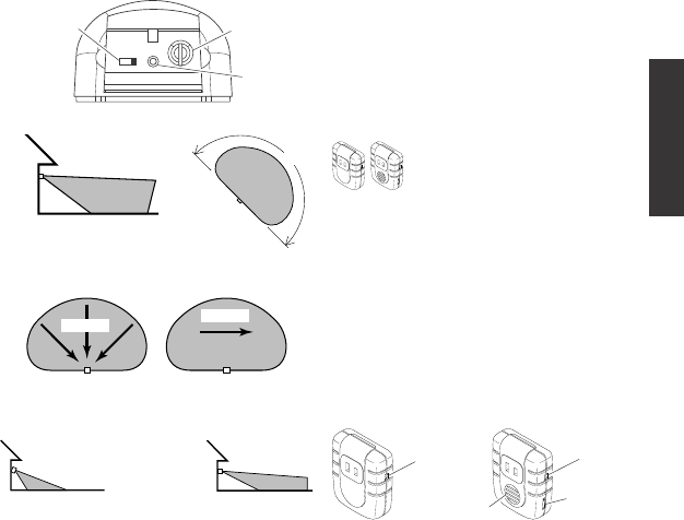
Maximum
Coverage Angle
Maximum Range
Coverage Area
Motion Sensor Sensitivity
The detector is most sensitive to motion across its field of view.
Motion Sensor Controls - Bottom View
Motion
Most SensitiveLeast Sensitive
Motion
Sensor Sensor
51TEST
ON-TIME
(MINUTES)
RANGE
MAX MIN
ON-TIME
Control
Sensitivity
Control
LED
Indicator
70 ft.
(21 m)
8 ft.
(2.4 m)
180°
Aim Sensor Down
for Short Coverage Aim Sensor Higher
for Long Coverage
Adjusting Motion Sensor Coverage
8
598-1116-08
DRAFT COPY
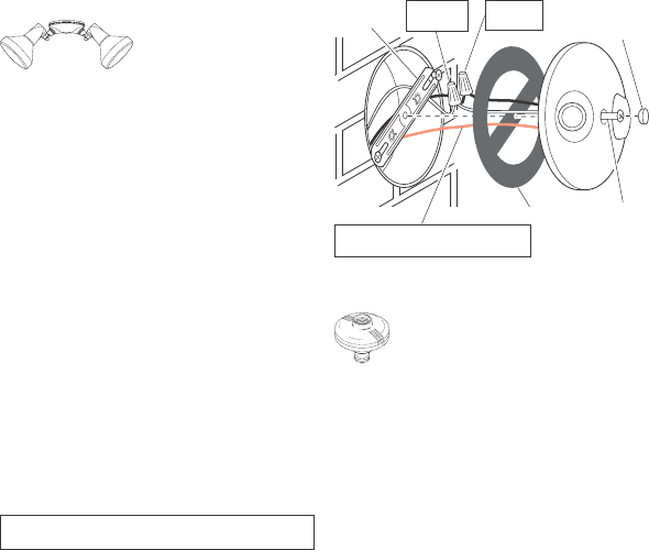
Junction box ground wire to green
ground screw on fixture.
Wiring Floodlight
Warning - Risk of fire. Do not aim the lamps at a combus-
tible surface within 3 ft. (1 m).
White to
White
Black to
Black
Gasket
Mounting
Strap
Mounting
Bolt
Rubber
Plug
LAMP SOCKET CONVERTER
Features and Ratings:
•Up to 150 Watt maximum incandescent load.
•No wiring required.
1. Screw module into light socket.
2. Screw incandescent bulb up to rated wattage into module.
Caution: Do not exceed the maximum load limits listed
above.
3. Check operation. Activate transmitter being used with re-
ceiver (see transmitter instructions). A signal will be sent to
the receiver to turn the receiver ON or OFF.
FLOODLIGHT
Features and Ratings:
•Up to 150 Watt maximum in-
candescent load or 240 Watt
maximum halogen load (up to
75 Watt maximum incandescent, or 120 Watt maximum halo-
gen, per lampholder).
•Minimal wiring required.
•Install fixture in accordance with local codes.
Turn power off at the fuse or circuit breaker.
1. Remove the existing light fixture.
2. Install the mounting strap as shown using two screws that fit
your junction box.
Note:
The plastic hanger can be used to hold the fixture while
wiring. Thread the small end of the plastic hanger through
the hole in the center of the cover plate. Insert the small end
into one of the slots on the mounting strap.
3. Route the wires from the light receiver through the large
gasket holes.
4. Twist the junction box wires and fixture wires together as
shown. Secure with UL approved wire connectors.
5. Align the cover plate and cover plate gasket. Secure with
mounting bolt.
6. Push the rubber plug firmly into place.
7. Not intended for waterproof junction boxes. Fixture should
be surface mount only. Caulk the wall plate mounting surface
with silicone weather sealant.
8. Adjust the lamp holders by loosening the lock nuts.
Note:
Do not
rotate the lamp holders more than 180° from the factory setting.
Caution: To avoid water damage and electrical shock, keep
lamp holders 30° below horizontal.
9. Screw incandescent bulb up to rated wattage into module.
When screwing in the lamps, do not overtighten.
Caution: Do not exceed the maximum load limits listed
above.
10. Check operation. Activate transmitter being used with re-
ceiver (see transmitter instructions). A signal will be sent to
the receiver to turn the receiver ON or OFF.

9
598-1116-08
ENGLISH
DRAFT COPY
TROUBLESHOOTING GUIDE
POSSIBLE CAUSE
1. Circuit breaker or fuse is turned off.
2. Switch on device is turned off.
3. Interrupted by another device.
4. Does not respond immediately after
installation.
5. Signals from transmitter are being
blocked, or transmitter is out of range.
6. Weak battery in the transmitter.
7. Dip switches on transmitter and re-
ceiver units do not match.
8. Device is defective.
1. Same as 5, 6, and 7 above.
1. Short term power line failure.
2. Another transmitter on the same
channel.
SYMPTOM
Device does not come on.
Device does not turn off.
Device comes on randomly.
SOLUTION
1. Verify circuit breaker or fuse is
turned on.
2. Verify switched device is turned on.
3. Change channels on transmitter and
receiver units.
4. Wait for 90 second initialization
period (remote motion sensor).
5. Check for metal objects that could
block the signal, or reposition the
transmitter.
6. Check battery charge and replace if
necessary.
7. Verify dip switch settings on trans-
mitter and receiver units are set the
same.
8. Test using different device.
1. Same as 5, 6, and 7 above.
1. Next transmission from transmitter
will reset receiver to correct state.
2. Change channels on transmitter and
receiver units.
REGULATORY INFORMATION
This device complies with Part 15 of the FCC Rules and RSS-210 of Industry Canada. Operation is subject to the following two
conditions: (1) this device may not cause harmful interference, and (2) this device must accept any interference received, including
interference that may cause undesired operation.
The term "IC:" before the radio certification number only signifies that Industry Canada technical specifications were met.
The user is cautioned that changes or modifications not expressly approved by the party responsible for regulatory compliance could
void the user’s authority to operate the equipment.
NO SERVICE PARTS AVAILABLE FOR THESE PRODUCTS
TECHNICAL SERVICE
(Do Not Send Products)
If you experience a problem, follow this guide. You may also want to visit our Web site at: www.desatech.com. If the problem persists,
call* for assistance at 1-800-858-8501, 7:30 AM to 4:30 PM CST (M-F). You may also write* to:
DESA Specialty Products™
P.O. Box 90004, Bowling Green, KY 42102-9004
ATTN: Technical Service Specialty Products
* If contacting Technical Service, please have the following information available: Model Number, Date of Purchase, and Place of Purchase.

10
598-1116-08
DRAFT COPY
TWO YEAR LIMITED WARRANTY
This is a “Limited Warranty” which gives you specific legal rights. You may also have other rights which vary from state to state
or province to province.
For a period of two years from the date of purchase, any malfunction caused by factory defective parts or workmanship will be
corrected at no charge to you. To obtain a refund or a replacement, call 1-800-858-8501 for instructions.
Not Covered - Repair service, adjustment and calibration due to misuse, abuse or negligence, light bulbs, batteries, and other
expendable items are not covered by this warranty. Unauthorized service or modification of the product or of any furnished
component will void this warranty in its entirety. This warranty does not include reimbursement for inconvenience, installation,
setup time, loss of use, unauthorized service, or return shipping charges.
This warranty covers only DESA Specialty Products™ assembled products and is not extended to other equipment and
components that a customer uses in conjunction with our products.
THIS WARRANTY IS EXPRESSLY IN LIEU OF ALL OTHER WARRANTIES, EXPRESS OR IMPLIED, INCLUDING ANY
WARRANTY, REPRESENTATION OR CONDITION OF MERCHANT ABILITY OR THAT THE PRODUCTS ARE FIT FOR
ANY PARTICULAR PURPOSE OR USE, AND SPECIFICALLY IN LIEU OF ALL SPECIAL, INDIRECT, INCIDENTAL, OR
CONSEQUENTIAL DAMAGES.
REPAIR OR REPLACEMENT SHALL BE THE SOLE REMEDY OF THE CUSTOMER AND THERE SHALL BE NO LIABILITY
ON THE PART OF DESA SPECIALTY PRODUCTS™ FOR ANY SPECIAL, INDIRECT, INCIDENTAL, OR CONSEQUENTIAL
DAMAGES, INCLUDING BUT NOT LIMITED TO ANY LOSS OF BUSINESS OR PROFITS, WHETHER OR NOT FORESEE-
ABLE. Some states or provinces do not allow the exclusion or limitation of incidental or consequential damages, so the above
limitation or exclusion may not apply to you. Proof of purchase is required for warranty claims.
DESA Specialty Products™ reserves the right to discontinue products and to change specifications at any time without incurring any
obligation to incorporate new features in products previously sold.