Heatiator NNXT4236IL NNXT3933I User Manual To The A0470564 63c3 4ce7 950c 142a12327bdb
User Manual: Heatiator NNXT4236IL NNXT3933I to the manual
Open the PDF directly: View PDF ![]() .
.
Page Count: 82
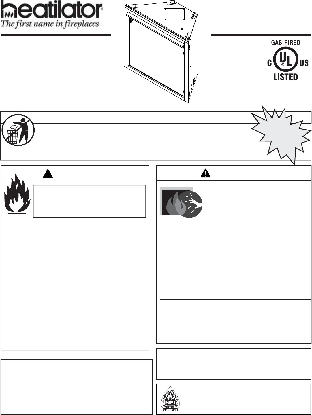
1Heatilator • Novus NNXT • 4055-879 • Rev. o • 2/12
Model(s):
NNXT4236I, NNXT4236IL
NNXT3933I, NNXT3933IL
Owner’s Manual
Installation and Operation
Installation and service of this appliance should be performed
by qualified personnel. Hearth & Home Technologies
suggests NFI certifi ed or factory-trained professionals, or
technicians supervised by an NFI certifi ed professional.
If the information in these instruc-
tions is not followed exactly, a
fi re may result causing property
damage, personal injury, or death.
• Do not store or use gasoline or other fl am-
mable vapors and liquids in the vicinity of
this or any other appliance.
• What to do if you smell gas:
- Do not try to light any appliance.
- Do not touch any electrical switch. Do not
use any phone in your building.
- Immediately call your gas supplier from
a neighbor’s phone. Follow the gas
supplier’s instructions.
- If you cannot reach your gas supplier, call
the fi re department.
• Installation and service must be performed
by a qualifi ed installer, service agency, or
the gas supplier.
WARNING
This appliance may be installed as an OEM installation
in manufactured home (USA only) or mobile home and
must be installed in accordance with the manufacturer’s
instructions and the manufactured home construction and
safety standard, Title 24 CFR, Part 3280 or Standard for
Installation in Mobile Homes, CAN/CSA Z240MH.
This appliance is only for use with the type(s) of gas
indicated on the rating plate.
DO NOT DISCARD THIS MANUAL
CAUTION
• Important operating and
maintenance instructions
included.
• Leave this manual with
party responsible for
use and operation.
• Read, understand and follow
these instructions for safe
installation and operation.
DO NOT
DISCARD
In the Commonwealth of Massachusetts installation must
be performed by a licensed plumber or gas fi tter;
See Table of Contents for location of additional
Commonwealth of Massachusetts requirements.
HOT SURFACES!
Glass and other surfaces are hot during
operation and cool down.
WARNING
• CAREFULLY SUPERVISE children in same room as
appliance.
• Alert children and adults to hazards of high
temperatures.
High temperatures may ignite clothing or other
fl ammable materials.
• Keep clothing, furniture, draperies and other combustibles
away.
Hot glass will cause burns.
• Do not touch glass until it is cooled
• NEVER allow children to touch glass
• Keep children away
This appliance has been supplied with an integral
barrier to prevent direct contact with the fi xed glass
panel. Do NOT operate the appliance with the barrier
removed.
Contact your dealer or Hearth & Home Technologies if the
barrier is not present or help is needed to properly install one.
Heatilator • Novus NNXT • 4055-879 • Rev. o • 2/122
Listing Label Information/Location
Model Name: ___________________________________________ Date purchased/installed: __________________
Serial Number: __________________________________________ Location on fi replace: _____________________
Dealership purchased from: _______________________________ Dealer Phone: __________________________
Notes: _______________________________________________________________________________________
_____________________________________________________________________________________________
A. Congratulations
Congratulations on selecting a Heatilator gas fi replace, an
elegant and clean alternative to wood burning fi replaces.
The Heatilator gas fi replace you have selected is designed
to provide the utmost in safety, reliability, and effi ciency.
As the owner of a new fi replace, you’ll want to read and
carefully follow all of the instructions contained in this
owner’s manual. Pay special attention to all cautions and
warnings.
This owner’s manual should be retained for future reference.
We suggest that you keep it with your other important
documents and product manuals.
The information contained in this owner’s manual, unless
noted otherwise, applies to all models and gas control
systems.
Your new Heatilator gas fi replace will give you years of
durable use and trouble-free enjoyment. Welcome to the
Heatilator family of fi replace products!
We recommend that you record the following pertinent
information about your fi replace.
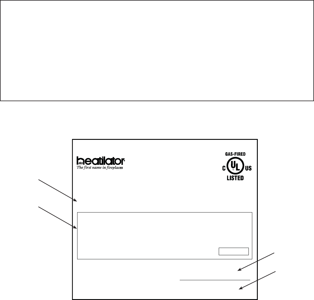
The model information regarding your specifi c fi replace can be found on
the rating plate usually located in the control area of the fi replace.
Homeowner Reference Information
Read this manual before installing or operating this appliance.
Please retain this owner’s manual for future reference.
Not Not for for use use with with solid solid fuel.fuel.
((Ne Ne doit doit pas pas entre entre utilise utilise avec avec un un combustible combustible solide).solide).
This This appliance appliance must must be be installed installed in in accordance accordance with with local local codes, codes, if if any; any; if if not, not, follow follow ANSI ANSI Z223.1Z223.1
in in the the USA USA or or CAN/CGA CAN/CGA B149 B149 installation installation codes. codes. (Installer (Installer l’appareil l’appareil selon selon les les codes codes ou ou reglementsreglements
locaux locaux ou, ou, en en l’absence l’absence de de tels tels reglements, reglements, selon selon les les codes codes d’installation d’installation CAN/CGA-B149.)CAN/CGA-B149.)
Type Type of of Gas Gas (Sorte (Sorte De De Gaz)Gaz)::
NNAATURALTURAL GASGAS
MADE MADE IN IN USAUSA
Minimum Minimum Permissible Permissible Gas Gas Supply Supply for for Purposes Purposes of of Input Input Adjustment.Adjustment.
Approved Approved Minimum Minimum (De (De Gaz) Gaz) AcceptableAcceptable 0.00.0 in in w.c.w.c. (Po. (Po. Col. Col. d’eau)d’eau)
Maximum Maximum Pressure Pressure (Pression)(Pression) 0.00.0 in in w.c.w.c. (Po. (Po. Col. Col. d’eau)d’eau)
Maximum Maximum Manifold Manifold Pressure Pressure (Pression)(Pression) 0.00.0 in in w.c.w.c. (Po. (Po. Col. Col. d’eau)d’eau)
Minimum Minimum Manifold Manifold Pressure Pressure (Pression)(Pression) 0.00.0 in in w.c.w.c. (Po. (Po. Col. Col. d’eau)d’eau)
Model:Model:
(Modele):(Modele):
SerialSerial
(Serie):(Serie):
ANSI ANSI Z21XX-XXXX Z21XX-XXXX · · CSA CSA 2.XX-MXX 2.XX-MXX · · UL307B
UL307B
XXXXXXXXXXXXXXXX
IN IN CANADACANADA
ALTITUDE:ALTITUDE: 0-0000 0-0000 FT.FT. 0000-0000FT.0000-0000FT.
MAX. MAX. INPUT INPUT BTUH:BTUH: 00,00000,000 00,00000,000
MIN. MIN. INPUT INPUT BTUH:BTUH: 00,00000,000 00,00000,000
ORIFICE ORIFICE SIZE:SIZE: #XXXXX#XXXXX #XXXXX#XXXXX XXXXXXXXXXXXXXXX
Total Total Electrical Electrical Requirements: Requirements: 000Vac, 000Vac, 00Hz., 00Hz., less less than than 00 00 AmperesAmperes
Heatilator, a brand of Hearth & Home Technologies, Inc.
7571 215th Street West, Lakeville, MN 55044
Gas and Electric
Information
Serial Number
Type of Gas
Model Number

3Heatilator • Novus NNXT • 4055-879 • Rev. o • 2/12
Safety Alert Key:
• DANGER! Indicates a hazardous situation which, if not avoided will result in death or serious injury.
• WARNING! Indicates a hazardous situation which, if not avoided could result in death or serious injury.
• CAUTION! Indicates a hazardous situation which, if not avoided, could result in minor or moderate injury.
• NOTICE: Used to address practices not related to personal injury.
Table of Contents
A. Congratulations 2
B. Limited Lifetime Warranty 5
1 Listing and Code Approvals
A. Appliance Certifi cation 7
B. Glass Specifi cations 7
C. BTU Specifi cations 7
D. High Altitude Installations 7
E. Non-Combustible Materials Specifi cation 7
F. Combustible Materials Specifi cation 7
G. Electrical Codes 7
H. Requirements for the Commonwealth
of Massachusetts 8
User Guide
2 Operating Instructions
A. Gas Fireplace Safety 9
B. Your Fireplace 9
C. Fan Kit (optional) 10
D. Clear Space 10
E. Decorative Doors and Fronts 10
F. Fixed Glass Assembly 10
G. Remote Controls, Wall Controls and Wall
Switches 10
H. IPI Battery Tray/Battery Installation 11
I. Control Module Operation 11
J. Before Lighting Fireplace 11
K. Lighting Instructions (IPI) 12
L. After Fireplace is Lit 13
M. Frequently Asked Questions 13
3 Maintenance and Service
A. Maintenance Tasks-Homeowner 14
B. Maintenance Tasks-Qualifi ed Service Technician 15
Installer Guide
4 Getting Started
A. Typical Appliance System 16
B. Design and Installation Considerations 17
C. Tools and Supplies Needed 17
D. Inspect Appliance and Components 17
5 Framing and Clearances
A. Select Appliance Location 18
B. Construct the Appliance Chase 19
C. Clearances 20
D. Mantel and Wall Projections 21
6 Termination Locations
A. Vent Termination Minimum Clearances 22
7 Vent Information and Diagrams
A. Approved Pipe 24
B. Vent Table Key 24
C. Use of Elbows 24
D. Measuring Standards 24
E. Vent Diagrams 25
8 Vent Clearances and Framing
A. Pipe Clearances to Combustibles 35
B. Wall Penetration Framing 35
C. Install the Ceiling Firestop 36
D. Install Attic Insulation Shield 37
9 Appliance Preparation
A. Top Vent 38
B. Rear Vent 39
C. Secure and Level the Appliance 40
10 Install Vent Pipe
A. Assemble Vent Sections (DVP Only) 41
B. Assemble Vent Sections (SLP Only) 42
C. Assemble Slip Sections 42
D. Secure the Vent Sections 43
E. Disassemble Vent Sections 43
F. Install Decorative Ceiling Components
(SLP only) 44
G. Install Metal Roof Flashing 45
H. Assemble and Install Storm Collar 45
I. Install Vertical Termination Cap 46
J. Install Decorative Wall Components (SLP only) 46
K. Heat Shield Requirements for Horizontal
Termination 46
L. Install Horizontal Termination Cap 47
11 Shrouds
A. HHT Shrouds 48
B. Field Constructed Shrouds 48
12 Gas Information
A. Fuel Conversion 50
B. Gas Pressure 50
C. Gas Connection 50
D. High Altitude Installations 50
13 Electrical Information
A. Wiring Requirements 51
B. Intellifi re Plus™ Ignition System Wiring 51
C. Optional Accessories Requirements 51
D. Electrical Service and Repair 52
E. Junction Box Installation 53
F. Wall Switch Installation for Fan (Optional) 53
G. Remote Control Installation & Operations 54
Heatilator • Novus NNXT • 4055-879 • Rev. o • 2/124
= Contains updated information.
14 Finishing
A. Mantel and Wall Projections 58
B. Facing Material 59
15 Appliance Setup
A. Remove the Packaging 60
B. Remove Screen Package Assembly 60
C. Remove the Shipping Materials 60
D. Removing Fixed Glass Assembly 60
E. Remove Top Log Pack 60
F. Remove Packing Material 60
G. Clean the Appliance 61
H. Accessories 61
I. Place the Rockwool 61
J. Place the Lava Rock 61
K. Place the Vermiculite 61
L. Assemble Logs 61
M. Replacing Fixed Glass Assembly 62
N. Air Shutter Setting 62
O. Remove Screen Protector 63
P. Unpackage the Hood & Floor Cover 63
Q. Install Hood 63
R. Install Control Heat Shield 63
S. Install Floor Cover 64
T. Close the Screen Assembly 65
16 Troubleshooting
A. Intellifi re Plus™ Intermittent Ignition System 66
17 Reference Materials
A. Appliance Dimension Diagram 68
B. Vent Components Diagrams 69
C. Service Parts 77
D. Optional Components 81
E. Contact Information 82
5Heatilator • Novus NNXT • 4055-879 • Rev. o • 2/12
B. Limited Lifetime Warranty
4021-645C 12-29-10 Page 1 of 2
Hearth & Home Technologies Inc.
LIMITED LIFETIME WARRANTY
Hearth & Home Technologies Inc., on behalf of its hearth brands (”HHT”), extends the following warranty for
HHT gas, wood, pellet, coal and electric hearth appliances that are purchased from an HHT authorized dealer.
WARRANTY COVERAGE:
HHT warrants to the original owner of the HHT appliance at the site of installation, and to any transferee taking ownership
of the appliance at the site of installation within two years following the date of original purchase, that the HHT appliance
will be free from defects in materials and workmanship at the time of manufacture. After installation, if covered compo-
nents manufactured by HHT are found to be defective in materials or workmanship during the applicable warranty period,
HHT will, at its option, repair or replace the covered components. HHT, at its own discretion, may fully discharge all of its
obligations under such warranties by replacing the product itself or refunding the verified purchase price of the product
itself. The maximum amount recoverable under this warranty is limited to the purchase price of the product. This warranty
is subject to conditions, exclusions and limitations as described below.
WARRANTY PERIOD:
Warranty coverage begins on the date of original purchase. In the case of new home construction, warranty coverage
begins on the date of first occupancy of the dwelling or six months after the sale of the product by an independent,
authorized HHT dealer/ distributor, whichever occurs earlier. The warranty shall commence no later than 24 months
following the date of product shipment from HHT, regardless of the installation or occupancy date. The warranty period for
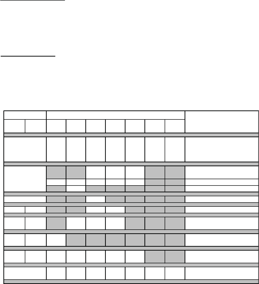
parts and labor for covered components is produced in the following table.
The term “Limited Lifetime” in the table below is defined as: 20 years from the beginning date of warranty coverage for
gas appliances, and 10 years from the beginning date of warranty coverage for wood, pellet, and coal appliances. These
time periods reflect the minimum expected useful lives of the designated components under normal operating conditions.
See conditions, exclusions, and limitations on next page.
Parts Labor Gas Wood Pellet EPA
Wood Coal Electric Venting
XXXXXXX
All parts and material except as
covered by Conditions,
Exclusions, and Limitations
listed
XXX Igniters, electronic components,
and
g
lass
XXXXX Factor
y
-installed blowers
X Molded refractor
y
p
anels
XFire
p
ots and burn
p
ots
5
y
ears 1
y
ear X X Castin
g
s and baffles
7 years 3 years X X X Manifold tubes,
HHT chimne
y
and termination
10
y
ears 1 year X Burners, logs and refractory
Limited
Lifetime 3 yearsXXXXX Firebox and heat exchanger
XXXXXXX All replacement parts
be
y
ond warrant
y
p
eriod
Warranty Period HHT Manufactured Appliances and Venting
1 Year
Components Covered
3 years
2 years
90 Days

Heatilator • Novus NNXT • 4055-879 • Rev. o • 2/126
B. Limited Lifetime Warranty (continued)
4021-645C 12-29-10 Page 2 of 2
WARRANTY CONDITIONS:
7KLVZDUUDQW\RQO\FRYHUV++7DSSOLDQFHVWKDWDUHSXUFKDVHGWKURXJKDQ++7DXWKRUL]HGGHDOHURUGLVWULEXWRU$OLVWRI
++7DXWKRUL]HGGHDOHUVLVDYDLODEOHRQWKH++7EUDQGHGZHEVLWHV
7KLVZDUUDQW\LVRQO\YDOLGZKLOHWKH++7DSSOLDQFHUHPDLQVDWWKHVLWHRIRULJLQDOLQVWDOODWLRQ
&RQWDFW\RXULQVWDOOLQJGHDOHUIRUZDUUDQW\VHUYLFH,IWKHLQVWDOOLQJGHDOHULVXQDEOHWRSURYLGHQHFHVVDU\SDUWVFRQWDFW
WKHQHDUHVW++7DXWKRUL]HGGHDOHURUVXSSOLHU$GGLWLRQDOVHUYLFHIHHVPD\DSSO\LI\RXDUHVHHNLQJZDUUDQW\VHUYLFH
IURPDGHDOHURWKHUWKDQWKHGHDOHUIURPZKRP\RXRULJLQDOO\SXUFKDVHGWKHSURGXFW
&KHFNZLWK\RXUGHDOHULQDGYDQFHIRUDQ\FRVWVWR\RXZKHQDUUDQJLQJDZDUUDQW\FDOO7UDYHODQGVKLSSLQJFKDUJHV
IRUSDUWVDUHQRWFRYHUHGE\WKLVZDUUDQW\
This warranty is void if:
7KHDSSOLDQFHKDVEHHQRYHUILUHGRURSHUDWHGLQDWPRVSKHUHVFRQWDPLQDWHGE\FKORULQHIOXRULQHRURWKHUGDPDJLQJ
FKHPLFDOV2YHUILULQJFDQEHLGHQWLILHGE\EXWQRWOLPLWHGWRZDUSHGSODWHVRUWXEHVUXVWFRORUHGFDVWLURQEXEEOLQJ
FUDFNLQJDQGGLVFRORUDWLRQRIVWHHORUHQDPHOILQLVKHV
7KHDSSOLDQFHLVVXEMHFWHGWRSURORQJHGSHULRGVRIGDPSQHVVRUFRQGHQVDWLRQ
7KHUHLVDQ\GDPDJHWRWKHDSSOLDQFHRURWKHUFRPSRQHQWVGXHWRZDWHURUZHDWKHUGDPDJHZKLFKLVWKHUHVXOWRIEXW
QRWOLPLWHGWRLPSURSHUFKLPQH\RUYHQWLQJLQVWDOODWLRQ
LIMITATIONS OF LIABILITY:
7KHRZQHU¶VH[FOXVLYHUHPHG\DQG++7¶VVROHREOLJDWLRQXQGHUWKLVZDUUDQW\XQGHUDQ\RWKHUZDUUDQW\H[SUHVVRU
LPSOLHGRULQFRQWUDFWWRUWRURWKHUZLVHVKDOOEHOLPLWHGWRUHSODFHPHQWUHSDLURUUHIXQGDVVSHFLILHGDERYH,QQR
HYHQWZLOO++7EHOLDEOHIRUDQ\LQFLGHQWDORUFRQVHTXHQWLDOGDPDJHVFDXVHGE\GHIHFWVLQWKHDSSOLDQFH6RPHVWDWHV
GRQRWDOORZH[FOXVLRQVRUOLPLWDWLRQRILQFLGHQWDORUFRQVHTXHQWLDOGDPDJHVVRWKHVHOLPLWDWLRQVPD\QRWDSSO\WR\RX
7KLVZDUUDQW\JLYHV\RXVSHFLILFULJKWV\RXPD\DOVRKDYHRWKHUULJKWVZKLFKYDU\IURPVWDWHWRVWDWH(;&(3772
7+((;7(173529,'('%</$:++70$.(612(;35(66:$55$17,(627+(57+$17+(:$55$17<
63(&,),('+(5(,17+('85$7,212)$1<,03/,(':$55$17<,6/,0,7('72'85$7,212)7+(
(;35(66(':$55$17<63(&,),('$%29(
WARRANTY EXCLUSIONS:
7KLVZDUUDQW\GRHVQRWFRYHUWKHIROORZLQJ
&KDQJHVLQVXUIDFHILQLVKHVDVDUHVXOWRIQRUPDOXVH$VDKHDWLQJDSSOLDQFHVRPHFKDQJHVLQFRORURILQWHULRUDQG
H[WHULRUVXUIDFHILQLVKHVPD\RFFXU7KLVLVQRWDIODZDQGLVQRWFRYHUHGXQGHUZDUUDQW\
'DPDJHWRSULQWHGSODWHGRUHQDPHOHGVXUIDFHVFDXVHGE\ILQJHUSULQWVDFFLGHQWVPLVXVHVFUDWFKHVPHOWHGLWHPV
RURWKHUH[WHUQDOVRXUFHVDQGUHVLGXHVOHIWRQWKHSODWHGVXUIDFHVIURPWKHXVHRIDEUDVLYHFOHDQHUVRUSROLVKHV
5HSDLURUUHSODFHPHQWRISDUWVWKDWDUHVXEMHFWWRQRUPDOZHDUDQGWHDUGXULQJWKHZDUUDQW\SHULRG7KHVHSDUWV
LQFOXGHSDLQWZRRGSHOOHWDQGFRDOJDVNHWVILUHEULFNVJUDWHVIODPHJXLGHVOLJKWEXOEVEDWWHULHVDQGWKHGLVFRORU-
DWLRQRIJODVV
0LQRUH[SDQVLRQFRQWUDFWLRQRUPRYHPHQWRIFHUWDLQSDUWVFDXVLQJQRLVH7KHVHFRQGLWLRQVDUHQRUPDODQGFRP-
SODLQWVUHODWHGWRWKLVQRLVHDUHQRWFRYHUHGE\WKLVZDUUDQW\
'DPDJHVUHVXOWLQJIURPIDLOXUHWRLQVWDOORSHUDWHRUPDLQWDLQWKHDSSOLDQFHLQDFFRUGDQFHZLWKWKHLQVWDOODWLRQ
LQVWUXFWLRQVRSHUDWLQJLQVWUXFWLRQVDQGOLVWLQJDJHQWLGHQWLILFDWLRQODEHOIXUQLVKHGZLWKWKHDSSOLDQFHIDLOXUHWR
LQVWDOOWKHDSSOLDQFHLQDFFRUGDQFHZLWKORFDOEXLOGLQJFRGHVVKLSSLQJRULPSURSHUKDQGOLQJLPSURSHURSHUD-
WLRQDEXVHPLVXVHFRQWLQXHGRSHUDWLRQZLWKGDPDJHGFRUURGHGRUIDLOHGFRPSRQHQWVDFFLGHQWRULPSURSHUO\
LQFRUUHFWO\SHUIRUPHGUHSDLUVHQYLURQPHQWDOFRQGLWLRQVLQDGHTXDWHYHQWLODWLRQQHJDWLYHSUHVVXUHRUGUDIWLQJ
FDXVHGE\WLJKWO\VHDOHGFRQVWUXFWLRQVLQVXIILFLHQWPDNHXSDLUVXSSO\RUKDQGOLQJGHYLFHVVXFKDVH[KDXVWIDQVRU
IRUFHGDLUIXUQDFHVRURWKHUVXFKFDXVHVXVHRIIXHOVRWKHUWKDQWKRVHVSHFLILHGLQWKHRSHUDWLQJLQVWUXFWLRQV
LQVWDOODWLRQRUXVHRIFRPSRQHQWVQRWVXSSOLHGZLWKWKHDSSOLDQFHRUDQ\RWKHUFRPSRQHQWVQRWH[SUHVVO\DXWKRUL]HG
DQGDSSURYHGE\++7PRGLILFDWLRQRIWKHDSSOLDQFHQRWH[SUHVVO\DXWKRUL]HGDQGDSSURYHGE\++7LQZULWLQJ
DQGRULQWHUUXSWLRQVRUIOXFWXDWLRQVRIHOHFWULFDOSRZHUVXSSO\WRWKHDSSOLDQFH
1RQ++7YHQWLQJFRPSRQHQWVKHDUWKFRPSRQHQWVRURWKHUDFFHVVRULHVXVHGLQFRQMXQFWLRQZLWKWKHDSSOLDQFH
$Q\SDUWRIDSUHH[LVWLQJILUHSODFHV\VWHPLQZKLFKDQLQVHUWRUDGHFRUDWLYHJDVDSSOLDQFHLVLQVWDOOHG
++7¶VREOLJDWLRQXQGHUWKLVZDUUDQW\GRHVQRWH[WHQGWRWKHDSSOLDQFH¶VFDSDELOLW\WRKHDWWKHGHVLUHGVSDFH,QIRUPD-
WLRQLVSURYLGHGWRDVVLVWWKHFRQVXPHUDQGWKHGHDOHULQVHOHFWLQJWKHSURSHUDSSOLDQFHIRUWKHDSSOLFDWLRQ&RQVLGHU-
DWLRQPXVWEHJLYHQWRDSSOLDQFHORFDWLRQDQGFRQILJXUDWLRQHQYLURQPHQWDOFRQGLWLRQVLQVXODWLRQDQGDLUWLJKWQHVVRI
WKHVWUXFWXUH
7Heatilator • Novus NNXT • 4055-879 • Rev. o • 2/12
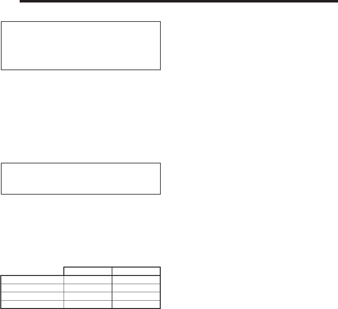
C. BTU Specifi cations
MODELS: NNXT4236I, NNXT4236IL, NNXT3933I,
NNXT3933IL
LABORATORY: Underwriters Laboratories, Inc. (UL)
TYPE: Vented Gas Fireplace Heaters
STANDARD: ANSI Z21.88-2002•CSA2.33-M2002•UL307B
This product is listed to ANSI standards for “Vented Gas
Fireplace Heaters” and applicable sections of “Gas Burn-
ing Heating Appliances for Manufactured Homes and
Recreational Vehicles”, and “Gas Fired Appliances for
Use at High Altitudes”.
E. Non-Combustible Materials Specifi cation
Material which will not ignite and burn. Such materials are
those consisting entirely of steel, iron, brick, tile, concrete,
slate, glass or plasters, or any combination thereof.
Materials that are reported as passing ASTM E 136,
Standard Test Method for Behavior of Materials in a
Vertical Tube Furnace at 750 ºC and UL763 shall be
considered non-combustible materials.
F. Combustible Materials Specifi cation
Materials made of or surfaced with wood, compressed
paper, plant fi bers, plastics, or other material that can ig-
nite and burn, whether fl ame proofed or not, or plastered
or unplastered shall be considered combustible materials.
NOT INTENDED FOR USE AS A PRIMARY HEAT SOURCE.
This appliance is tested and approved as either supplemental
room heat or as a decorative appliance. It should not be fac-
tored as primary heat in residential heating calculations.
D. High Altitude Installations
NOTICE: If the heating value of the gas has been reduced,
these rules do not apply. Check with your local gas utility or
authorities having jurisdiction.
When installing above 2000 feet elevation:
• In the USA: Reduce input rate 4% for each 1000 feet
above 2000 feet.
• In CANADA: Reduce input rate 10% for elevations
between 2000 feet and 4500 feet. Above 4500 feet,
consult local gas utility.
Check with your local gas utility to determine proper
orifi ce size.
NOTICE: This installation must conform with local codes.
In the absence of local codes you must comply with the
National Fuel Gas Code, ANSI Z223.1-latest edition in
the U.S.A. and the CAN/CGA B149 Installation Codes in
Canada.
1
1 Listing and Code Approvals
A. Appliance Certifi cation
G. Electrical Codes
NOTICE: This appliance must be electrically wired
and grounded in accordance with local codes or, in the
absence of local codes, with National Electric Code
ANSI/NFPA 70-latest edition or the Canadian Electric
Code CSA C22.1.
• A 120 VAC circuit for this product must be protected with
ground-fault circuit-interrupter protection, in compliance
with the applicable electrical codes, when it is installed
in locations such as in bathrooms or near sinks.
Novus NNXT4236 NNXT3933
Max/Min Input Rate (NG) 31,000/18,500 29,000/16,000
Orifi ce Size (NG) #37/.104/2.65 mm #39/.0995/2.53 mm
Max/Min Input Rate (LP) 30,000/17,000 27,000/15,750
Orifi ce Size (LP) #52/.0635/1.62 mm .061/155 mm
B. Glass Specifi cations
This appliance is equipped with 5 mm ceramic glass. Re-
place glass only with 5 mm ceramic glass. Please contact
your dealer for replacement glass.

Heatilator • Novus NNXT • 4055-879 • Rev. o • 2/128
H. Requirements for the Commonwealth of
Massachusetts
For all side wall horizontally vented gas fueled equipment
installed in every dwelling, building or structure used in
whole or in part for residential purposes, including those
owned or operated by the Commonwealth and where the
side wall exhaust vent termination is less than seven (7)
feet above fi nished grade in the area of the venting, in-
cluding but not limited to decks and porches, the following
requirements shall be satisfi ed:
Installation of Carbon Monoxide Detectors
At the time of installation of the side wall horizontal
vented gas fueled equipment, the installing plumber or
gas fi tter shall observe that a hard wired carbon mon-
oxide detector with an alarm and battery back-up is
installed on the fl oor level where the gas equipment is
to be installed. In addition, the installing plumber or gas
fi tter shall observe that a battery operated or hard wired
carbon monoxide detector with an alarm is installed on
each additional level of the dwelling, building or struc-
ture served by the side wall horizontal vented gas fueled
equipment. It shall be the responsibility of the property
owner to secure the services of qualifi ed licensed profes-
sionals for the installation of hard wired carbon monoxide
detectors.
In the event that the side wall horizontally vented gas
fueled equipment is installed in a crawl space or an attic,
the hard wired carbon monoxide detector with alarm and
battery back-up may be installed on the next adjacent
fl oor level.
In the event that the requirements of this subdivision can
not be met at the time of completion of installation, the
owner shall have a period of thirty (30) days to comply
with the above requirements; provided, however, that dur-
ing said thirty (30) day period, a battery operated carbon
monoxide detector with an alarm shall be installed.
Approved Carbon Monoxide Detectors
Each carbon monoxide detector as required in accor-
dance with the above provisions shall comply with NFPA
720 and be ANSI/UL 2034 listed and IAS certifi ed.
Signage
A metal or plastic identifi cation plate shall be permanently
mounted to the exterior of the building at a minimum
height of eight (8) feet above grade directly in line with
the exhaust vent terminal for the horizontally vented gas
fueled heating appliance or equipment. The sign shall
read, in print size no less than one-half (1/2) in. in size,
“GAS VENT DIRECTLY BELOW. KEEP CLEAR OF ALL
OBSTRUCTIONS”.
Inspection
The state or local gas inspector of the side wall horizon-
tally vented gas fueled equipment shall not approve the
installation unless, upon inspection, the inspector ob-
serves carbon monoxide detectors and signage installed
in accordance with the provisions of 248 CMR 5.08(2)(a)1
through 4.
Exemptions
The following equipment is exempt from 248 CMR
5.08(2)(a)1 through 4:
• The equipment listed in Chapter 10 entitled “Equipment
Not Required To Be Vented” in the most current edition
of NFPA 54 as adopted by the Board; and
• Product Approved side wall horizontally vented gas
fueled equipment installed in a room or structure
separate from the dwelling, building or structure used
in whole or in part for residential purposes.
MANUFACTURER REQUIREMENTS
Gas Equipment Venting System Provided
When the manufacturer of Product Approved side wall
horizontally vented gas equipment provides a venting
system design or venting system components with the
equipment, the instructions provided by the manufacturer
for installation of the equipment and the venting system
shall include:
• Detailed instructions for the installation of the venting
system design or the venting system components;
and
• A complete parts list for the venting system design or
venting system.
Gas Equipment Venting System NOT Provided
When the manufacturer of a Product Approved side
wall horizontally vented gas fueled equipment does not
provide the parts for venting the fl ue gases, but identi-
fi es “special venting systems”, the following requirements
shall be satisfi ed by the manufacturer:
• The referenced “special venting system” instructions
shall be included with the appliance or equipment
installation instructions; and
• The “special venting systems” shall be Product
Approved by the Board, and the instructions for that
system shall include a parts list and detailed installation
instructions.
A copy of all installation instructions for all Product Ap-
proved side wall horizontally vented gas fueled equip-
ment, all venting instructions, all parts lists for venting
instructions, and/or all venting design instructions shall
remain with the appliance or equipment at the completion
of the installation.
See Gas Connection section for additional Common-
wealth of Massachusetts requirements.
Note: The following requirements reference various
Massachusetts and national codes not contained in this
document.
9Heatilator • Novus NNXT • 4055-879 • Rev. o • 2/12
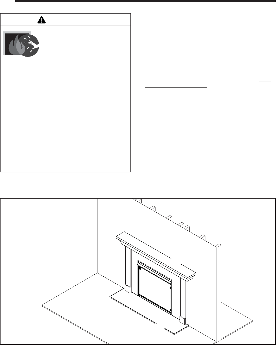
Decorative Doors
(not shown)
Section 2
Fixed Glass Assembly
Section 15
Mantel
Hearth
(not required)
Clear Space
Section 2
Fan Kits
Section 2
Figure 2.1 General Operating Parts
B. Your Fireplace
WARNING! DO NOT operate fi replace before reading and
understanding operating instructions. Failure to operate
fi replace according to operating instructions could cause
fi re or injury.
If you expect that small children or vulnerable adults may
come into contact with this fi replace, the following precau-
tions are recommended:
A. Gas Fireplace Safety • Install a physical barrier such as:
- A decorative fi rescreen.
- Adjustable safety gate.
• Install a switch lock or a wall/remote control with child
protection lockout feature.
• Keep remote controls out of reach of children.
• Never leave children alone near a hot fi replace, whether
operating or cooling down.
• Teach children to NEVER touch the fi replace.
• Consider not using the fi replace when children will be
present.
Contact your dealer for more information, or visit: www.
hpba.org/safety-information.
To prevent unintended operation when not using your
fi replace for an extended period of time (summer months,
vacations, trips, etc):
• Remove batteries from remote controls.
• Turn off wall controls.
• Unplug 6-volt power supply and/or remove batteries.
• Turn off gas controls valve on standing pilot models.
2
2 Operating Instructions
User Guide
HOT SURFACES!
Glass and other surfaces are hot
during operation and cool down.
Hot glass will cause burns.
• Do not touch glass until it is cooled
• NEVER allow children to touch glass
• Keep children away
• CAREFULLY SUPERVISE children in
WARNING
same room as appliance.
• Alert children and adults to hazards of high
temperatures.
High temperatures may ignite clothing or other
fl ammable materials.
• Keep clothing, furniture, draperies and other
combustibles away.
This appliance has been supplied with an integral
barrier to prevent direct contact with the fi xed glass
panel. Do NOT operate the appliance with the barrier
removed.
Contact your dealer or Hearth & Home Technologies if the
barrier is not present or help is needed to properly install one.
Heatilator • Novus NNXT • 4055-879 • Rev. o • 2/1210
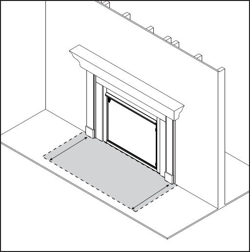
CLEAR SPACE
3 FT. IN FRONT OF FIREPLACE
D. Clear Space
WARNING! DO NOT place combustible objects in front of
the fi replace or block louvers. High temperatures may start
a fi re. See Figure 2.2.
Avoid placing candles and other heat-sensitive objects on
mantel or hearth. Heat may damage these objects.
Figure 2.2 Clear Space
C. Fan Kit (optional)
If desired, a fan kit may be added. Contact your dealer to
order the correct fan kit.
F. Fixed Glass Assembly
See Section 15.D.
E. Decorative Doors and Fronts
WARNING! Risk of Fire! Install ONLY doors or fronts
approved by Hearth & Home Technologies. Unapproved
doors or fronts may cause fi replace to overheat.
This fi replace has been supplied with an integral barrier to
prevent direct contact with the fi xed glass panel. DO NOT
operate the fi replace with the barrier removed.
Contact your dealer or Hearth & Home Technologies if the
barrier is not present or help is needed to properly install
one.
For more information refer to the instructions supplied
with your decorative door or front.
G. Remote Controls, Wall Controls and Wall
Switches
This appliance comes supplied with an RC200 hand-held
remote.
• Refer to Section 13.G. for operating instructions.
• Other controls are available. See your dealer for full
details.
11Heatilator • Novus NNXT • 4055-879 • Rev. o • 2/12
J. Before Lighting Fireplace
Before operating this fi replace for the fi rst time, have a
qualifi ed service technician:
• Verify all shipping materials have been removed from
inside and/or underneath the fi rebox.
• Review proper placement of logs, rockwool and/or other
decorative materials.
• Check the wiring.
• Check the air shutter adjustment.
• Ensure that there are no gas leaks.
• Ensure that the glass is sealed and in the proper position
and that the integral barrier is in place.
WARNING! Risk of Fire or Asphyxiation! DO NOT oper-
ate fi replace with fi xed glass assembly removed.
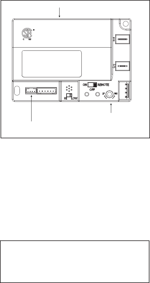
NG/LP SETTING
WIRE LEAD FROM REGULATOR CONNECTS HERE
MODULE
Figure 2.3 Control Module
H. IPI Battery Tray/Battery Installation
The IntelliFire PlusTM system has a battery backup option.
Battery longevity and performance will be affected by the
service temperatures of this appliance.
NOTICE: Batteries should only be used as a power source
in the event of an emergency such as an outage.
I. Control Module Operation
1. The control module has an ON/OFF/REMOTE selector
switch that must be set. See Figure 2.3.
OFF Position: Appliance will ignore all power inputs and
will not respond to any commands from a wall switch or
remote. The unit should be in the OFF position during
installation, service, battery installation, fuel conversion,
and in the event that the control goes into LOCK-OUT
mode as a result of an error code.
ON Position: Appliance will ignite and run continuously
in the HI fl ame setting, with no adjustment in fl ame
output. This mode of operation is primarily used for
initial installation or power outage operation with battery
backup.
REMOTE Position: Appliance will initiate commands
from an optional wired wall switch and/or the wireless
remote.
2. If using a wired wall switch with the module in REMOTE
mode, the fl ame output can be adjusted with the HI/LO
selector switch on the module. See Figure 2.3. Note
that the fl ame HI/LO selector switch will become inactive
once an optional remote control is programmed to the
control module. Note that the control module will always
ignite the fi replace on HI and remain so for the initial 10
seconds of operation. If the HI/LO is switched to the
LO position, the fl ame output will automatically drop to
the lowest setting after the fl ame has been established
for 10 sec. After this 10 second period, the fl ame can
be adjusted from HI to LO with the switch.
3. The control module has safety feature that automatically
shuts down the fi replace after 9 hours of continuous
operation without receiving a command from the remote.
4. If you intend to use both an optional wired wall switch
and the remote control to operate your fi replace, the wall
switch will override any commands given by the remote.
5. Module Reset
This module may lock-out under certain conditions.
When this occurs, the appliance will not ignite or respond
to commands. The module will go into lock-out mode
by emitting three audible beeps, then continuously
displaying a RED/GREEN error code at its status
indicator LED.
• Check battery tray. Remove batteries if installed.
Batteries should only be installed for use during power
outages. See Section H.
• Locate the module selector switch. (See Figure 2.3).
• Set the module selector switch to the OFF position.
• Wait fi ve (5) minutes to allow possible accumulated gas
to clear.
• Set the module selector switch to ON or REMOTE
position.
• Start the appliance.
WARNING! Risk of Explosion! DO NOT press the mod-
ule reset switch more than one time within a fi ve minute
time period. Gas may accumulate in fi rebox. Call a quali-
fi ed service technician.
Nine Hour Safety Shutdown Feature
This appliance has a safety feature that automatically
shuts down the fi replace after 9 hours of continuous
operation without receiving a command from the
remote.
Heatilator • Novus NNXT • 4055-879 • Rev. o • 2/1212
K. Lighting Instructions (IPI)
• For normal use, activate/deactivate your fi replace with the wall switch or remote control.
• The IPI system may be operated with four AA-cell batteries. When using batteries, unplug the power supply. To prolong
battery life, remove them when using the power supply.
• If your fi replace must be deactivated for serviced or an extended period of time, follow the instructions below.
1. This appliance is equipped with an ignition
device which automatically lights the burner.
DO NOT try to light the burner by hand.
2. Wait fi ve (5) minutes to clear out any gas.
Then smell for gas, including near the fl oor. If
you smell gas, STOP! Follow “B” in the Safety
Information located on the left side of this la-
bel. If you do not smell gas, go to next step.
3. To light the burner:
Equipped with wall switch: Turn ON/OFF switch
to ON.
Equipped with remote or wall control: Press
ON or FLAME button.
Equipped with thermostat: Set temperature to
desired setting.
4. If the appliance does not light after three tries,
call your service technician or gas supplier.
LIGHTING
INSTRUCTIONS (IPI)
TO TURN OFF
GAS TO APPLIANCE
1. Equipped with wall switch: Turn ON/OFF switch
to OFF.
Equipped with remote or wall control: Press
OFF button.
Equipped with thermostat: Set temperature to
lowest setting.
2. Service technician should turn off electric
power to the control when performing service.
FOR YOUR SAFETY
READ BEFORE LIGHTING
WARNING: If you do not follow these instructions exactly, a fi re
or explosion may result causing property damage, personal injury
or loss of life.
CAUTION:
NOT FOR USE
WITH SOLID FUEL
WARNING:
593-913G
GAS
VALVE
For additional information on operating your
Hearth & Home Technologies fi replace, please refer to www.fi replaces.com.
A. This appliance is equipped with an
intermittent pilot ignition (IPI) device
which automatically lights the burn-
er. DO NOT try to light the burner by
hand.
B. BEFORE LIGHTING, smell all around
the appliance area for gas. Be sure to
smell next to the fl oor because some
gas is heavier than air and will settle
on the fl oor.
WHAT TO DO IF YOU SMELL GAS
• DO NOT try to light any appliance.
• DO NOT touch any electric switch; do
not use any phone in your building.
DO NOT CONNECT LINE VOLT-
AGE (110/120 VAC OR 220/240
VAC) TO THE CONTROL VALVE.
Improper installation, adjustment, al-
teration, service or maintenance can
cause injury or property damage. Re-
fer to the owner’s information manual
provided with this appliance.
This appliance needs fresh air for
safe operation and must be installed
so there are provisions for adequate
combustion and ventilation air.
If not installed, operated, and main-
tained in accordance with the manufac-
turer’s instructions, this product could
expose you to substances in fuel or
fuel combustion which are known to
the State of California to cause can-
cer, birth defects, or other reproductive
harm.
Keep burner and control compartment
clean. See installation and operating
instructions accompanying appliance.
Hot while in operation. DO NOT touch.
Keep children, clothing, furniture, gaso-
line and other liquids having fl ammable
vapors away.
DO NOT operate the appliance with
fi xed glass assembly removed, cracked
or broken. Replacement of the fi xed
glass assembly should be done by a
licensed or qualifi ed service person.
• Immediately call your gas supplier
from a neighbor’s phone. Follow the
gas supplier’s instructions.
• If you cannot reach your gas sup-
plier, call the fi re department.
C. DO NOT use this appliance if any
part has been under water. Imme-
diately call a qualifi ed service tech-
nician to inspect the appliance and
to replace any part of the control
system and any gas control which
has been under water.
For use with natural gas and propane.
A conversion kit, as supplied by the
manufacturer, shall be used to convert
this appliance to the alternate fuel.
Also Certifi ed for Installation in a
Bedroom or a Bedsitting Room.
For assistance or additional informa-
tion, consult a qualifi ed installer, ser-
vice agency or the gas supplier.
Final inspection by

13Heatilator • Novus NNXT • 4055-879 • Rev. o • 2/12
Initial Break-in Procedure
• The fireplace should be run three to four hours
continuously on high.
• Turn the fi replace off and allow it to completely cool.
• Remove fi xed glass assembly. See Section 15.D.
• Clean fi xed glass assembly. See Section 3.
• Replace the fi xed glass assembly and run continuously
on high an additional 12 hours.
This cures the materials used to manufacture the fi re-
place.
NOTICE! Open windows for air circulation during fi replace
break-in.
• Some people may be sensitive to smoke and
odors.
• Smoke detectors may activate.
L. After Fireplace is Lit
M. Frequently Asked Questions
ISSUE SOLUTIONS
Condensation on the glass This is a result of gas combustion and temperature variations. As the appliance warms, this
condensation will disappear.
Blue fl ames This is a result of normal operation and the fl ames will begin to yellow as the appliance is allowed
to burn for 20 to 40 minutes.
Odor from appliance When fi rst operated, this appliance may release an odor for the fi rst several hours. This is caused
by the curing of materials from manufacturing. Odor may also be released from fi nishing materials
and adhesives used near the appliance. These circumstances may require additional curing
related to the installation environment.
Film on the glass This is a normal result of the curing process of the paint and logs. Glass should be cleaned within
3 to 4 hours of initial burning. A non-abrasive cleaner such as gas appliance glass cleaner may be
necessary. See your dealer.
Metallic noise Noise is caused by metal expanding and contracting as it heats up and cools down, similar to the
sound produced by a furnace or heating duct. This noise does not affect the operation or longevity
of the appliance.
Is it normal to see the pilot
fl ame burn continually? In an IntelliFire Plus™ ignition system (IPI), the pilot fl ame should turn off when appliance is
turned off. Some optional control systems available with IPI models may allow pilot fl ame to
remain lit. In a standing pilot system the pilot will always stay on.

Heatilator • Novus NNXT • 4055-879 • Rev. o • 2/1214
Glass Cleaning
Frequency: Seasonally
By: Homeowner
Tools Needed: Protective gloves, glass cleaner, drop
cloth and a stable work surface.
CAUTION! Handle fi xed glass assembly with care.
Glass is breakable.
• Avoid striking, scratching or slamming glass
• Avoid abrasive cleaners
• DO NOT clean glass while it is hot
• Prepare a work area large enough to accommodate fi xed
glass assembly and door frame by placing a drop cloth
on a fl at, stable surface.
Note: Fixed glass assembly and gasketing may have
residue that can stain carpeting or fl oor surfaces.
• Remove door or decorative front from fi replace and set
aside on work surface.
• See Section 15.D. for instructions to remove fi xed glass
assembly.
• Clean glass with a non-abrasive commercially available
cleaner.
- Light deposits: Use a soft cloth with soap and water
- Heavy deposits: Use commercial fi replace glass cleaner
(consult with your dealer)
• Carefully set fi xed glass assembly in place on fi replace.
Hold glass in place with one hand and secure glass
latches with the other hand.
• Reinstall door or decorative front.
3
3 Maintenance and Service
A. Maintenance Tasks-Homeowner
The following tasks may be performed annually by the
homeowner. If you are uncomfortable performing any of
the listed tasks, please call your dealer for a service ap-
pointment.
More frequent cleaning may be required due to lint from
carpeting or other factors. Control compartment, burner
and circulating air passageway of the fi replace must be
kept clean.
CAUTION! Risk of Burns! The fi replace should be
turned off and cooled before servicing.
When properly maintained, your fi replace will give you
many years of trouble-free service. We recommend an-
nual service by a qualifi ed service technician.
Doors, Surrounds, Fronts
Frequency: Annually
By: Homeowner
Tools needed: Protective gloves, stable work surface
• Assess condition of screen and replace as necessary.
• Inspect for scratches, dents or other damage and repair
as necessary.
• Check that louvers are not blocked.
• Vacuum and dust surfaces.
Any safety screen or guard removed for servicing must be
replaced prior to operating the fi replace.
Installation and repair should be done by a qualifi ed
service technician only. The fi replace should be inspect-
ed before use and at least annually by a professional
service person.
Remote Control
Frequency: Seasonally
By: Homeowner
Tools needed: Replacement batteries and remote control
instructions.
• Locate remote control transmitter and receiver.
• Verify operation of remote. Refer to remote control
operation instructions for proper calibration and setup
procedure.
• Place batteries as needed in remote transmitters and
battery-powered receivers.
• Place remote control out of reach of children.
If not using your fi replace for an extended period of time
(summer months, vacations/trips, etc), to prevent unin-
tended operation:
• Remove batteries from remote controls.
• Unplug 6-volt power supply on IPI models.
Venting
Frequency: Seasonally
By: Homeowner
Tools needed: Protective gloves and safety glasses.
• Inspect venting and termination cap for blockage or
obstruction such plants, bird nests, leaves, snow, debris,
etc.
• Verify termination cap clearance to subsequent
construction (building additions, decks, fences, or
sheds). See Section 6.
• Inspect for corrosion or separation.
• Verify weather stripping, sealing and fl ashing remains
intact.
• Inspect draft shield to verify it is not damaged or
missing.
15Heatilator • Novus NNXT • 4055-879 • Rev. o • 2/12
Control Compartment and Firebox Top
Frequency: Annually
By: Qualifi ed Service Technician
Tools needed: Protective gloves, vacuum cleaner, dust
cloths
• Vacuum and wipe out dust, cobwebs, debris or pet hair.
Use caution when cleaning these areas. Screw tips that
have penetrated the sheet metal are sharp and should
be avoided.
• Remove all foreign objects.
• Verify unobstructed air circulation.
B. Maintenance Tasks-Qualifi ed Service
Technician
The following tasks must be performed by a qualifi ed
service technician.
Logs
Frequency: Annually
By: Qualifi ed Service Technician
Tools needed: Protective gloves.
• Inspect for damaged or missing logs. Replace as
necessary. Refer to Section 15 for log placement
instructions.
• Verify correct log placement and no fl ame impingement
causing sooting. Correct as necessary.
Firebox
Frequency: Annually
By: Qualifi ed Service Technician
Tools needed: Protective gloves, sandpaper, steel wool,
cloths, mineral spirits, primer and touch-up paint.
• Inspect for paint condition, warped surfaces, corrosion
or perforation. Sand and repaint as necessary.
• Replace fi replace if fi rebox has been perforated.
Gasket Seal and Glass Assembly Inspection
Frequency: Annually
By: Qualifi ed Service Technician
Tools needed: Protective gloves, drop cloth and a stable
work surface.
• Inspect gasket seal and its condition.
• Inspect fi xed glass assembly for scratches and nicks
that can lead to breakage when exposed to heat.
• Confi rm there is no damage to glass or glass frame.
Replace as necessary.
• Verify that fi xed glass assembly is properly retained and
attachment components are intact and not damaged.
Replace as necessary.
Burner Ignition and Operation
Frequency: Annually
By: Qualifi ed Service Technician
Tools needed: Protective gloves, vacuum cleaner, whisk
broom, fl ashlight, voltmeter, indexed drill bit set, and a
manometer.
• Verify burner is properly secured and aligned with pilot
or igniter.
• Clean off burner top, inspect for plugged ports, corrosion
or deterioration. Replace burner if necessary.
• Replace rockwool with new dime-size pieces. DO NOT
block ports or obstruct lighting paths. Refer to Section
15 for proper rockwool placement.
• Verify batteries have been removed from battery back-
up IPI systems to prevent premature battery failure or
leaking.
• Check for smooth lighting and ignition carryover to all
ports. Verify that there is no ignition delay.
• Inspect for lifting or other fl ame problems.
• Verify air shutter setting is correct. See Section 15 for
required air shutter setting. Verify air shutter is clear of
dust and debris.
• Inspect orifi ce for soot, dirt and corrosion. Verify orifi ce
size is correct. See Service Parts List for proper orifi ce
sizing.
• Verify manifold and inlet pressures. Adjust regulator as
required.
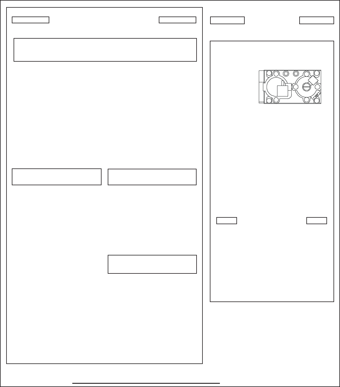
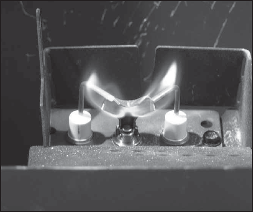
• Inspect pilot fl ame pattern and strength. See Figure 3.1
for proper pilot fl ame pattern. Clean or replace orifi ce
spud as necessary.
• Inspect thermocouple/thermopile or IPI fl ame sensing
rod for soot, corrosion and deterioration. Polish with fi ne
steel wool or replace as required.
• Verify thermocouple/thermopile or IPI millivolt output.
Replace as necessary.
Figure 3.1 IPI Pilot Flame Patterns
Heatilator • Novus NNXT • 4055-879 • Rev. o • 2/1216
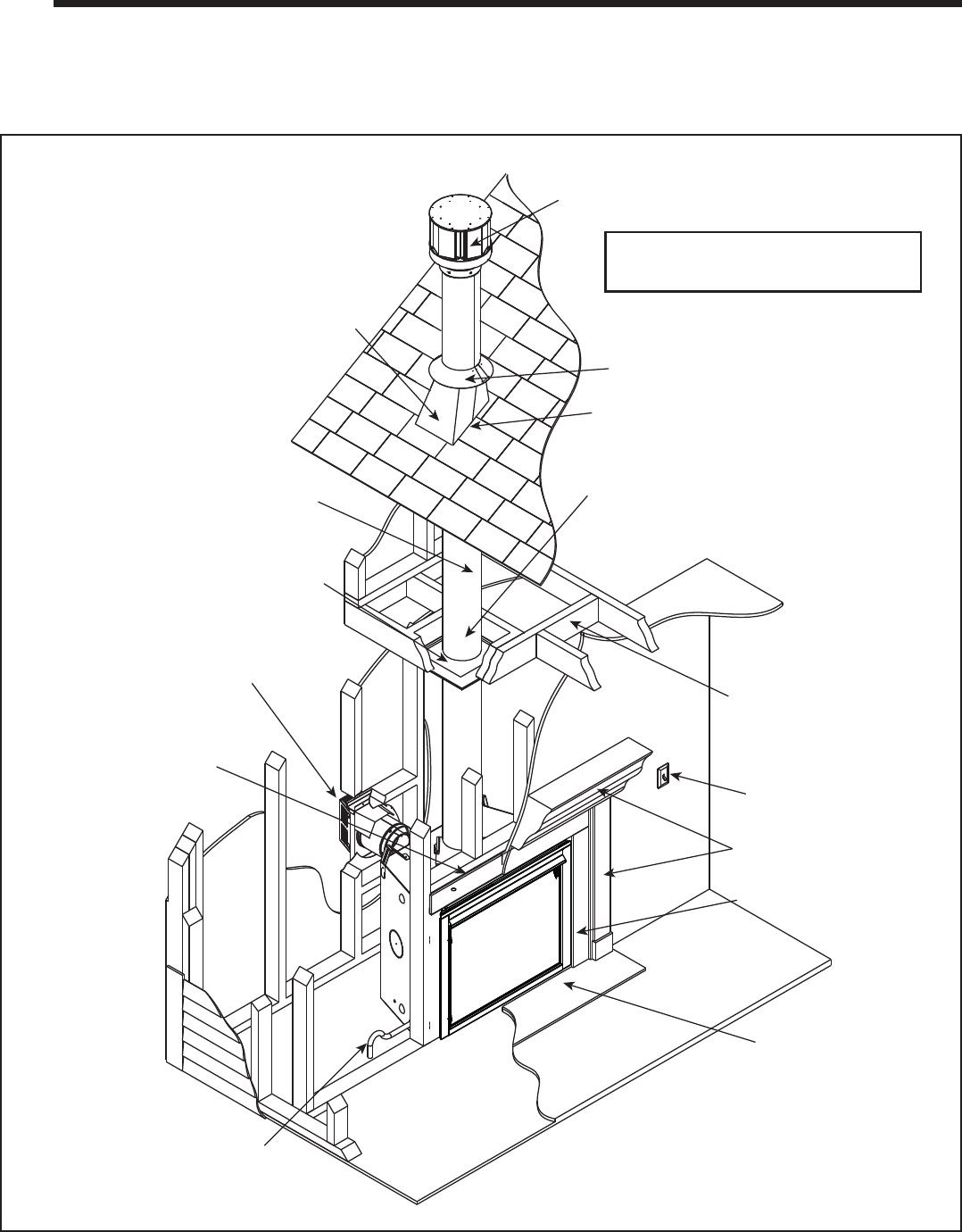
NOTE: An installation will have either a
vertical termination or a horizontal
termination. It will not have both (as shown).
Noncombustible Roof Flashing
maintains minimum clearance
around pipe (Section 10)
Ceiling Firestop on
floor of attic (Section 8)
Vent Pipe (Section 8)
Horizontal Termination Cap
(Section 10)
Framing/Header
(Section 5)
Gas Line
(Section 12)
Hearth Extension
(Not required)
Surround (Section 14)
Mantel & Mantel Leg
(Section 5 & 14)
Optional Wall Switch
(Section 12)
Framing headed off in
ceiling joists (Section 8)
Attic Insulation Shield (not shown) must be used
here to keep insulation away from vent pipe if
attic is insulated (Section 8)
Vent Pipe penetrates roof preferably
without affecting roof rafters
Storm Collar
(Section 10)
Vertical Termination Cap
(Section 10)
A. Typical Appliance System
NOTICE: Illustrations and photos refl ect typical installations and are for design purposes only. Illustrations/diagrams are not
drawn to scale. Actual product may vary from pictures in manual
Figure 4.1 Typical System
4
4 Getting Started
Installer Guide
Note: Dual venting confi gurations
ARE NOT allowed. Appliance
MUST be vented EITHER vertically
OR horizontally.

17Heatilator • Novus NNXT • 4055-879 • Rev. o • 2/12
B. Design and Installation Considerations
Heatilator direct vent gas appliances are designed to op-
erate with all combustion air siphoned from outside of the
building and all exhaust gases expelled to the outside. No
additional outside air source is required.
Installation MUST comply with local, regional, state and
national codes and regulations. Consult insurance carrier,
local building inspector, fi re offi cials or authorities having
jurisdiction over restrictions, installation inspection and
permits.
Before installing, determine the following:
• Where the appliance is to be installed.
• The vent system confi guration to be used.
• Gas supply piping.
• Electrical wiring requirements.
• Framing and fi nishing details.
• Whether optional accessories—devices such as a fan,
wall switch, or remote control—are desired.
D. Inspect Appliance and Components
• Carefully remove the appliance and components from
the packaging.
• The vent system components and decorative doors and
fronts may be shipped in separate packages.
• If packaged separately, the log set and appliance grate
must be installed.
• Report to your dealer any parts damaged in shipment,
particularly the condition of the glass.
• Read all of the instructions before starting the installation.
Follow these instructions carefully during the installation
to ensure maximum safety and benefi t.
C. Tools and Supplies Needed
Before beginning the installation be sure that the following
tools and building supplies are available.
Tape measure Framing material
Pliers Non-corrosive leak check solution
Hammer Phillips screwdriver
Gloves Framing square
Voltmeter Electric drill and bits (1/4 in.)
Plumb line Safety glasses
Level Reciprocating saw
Manometer Flat blade screwdriver
1/2 - 3/4 in. length, #6 or #8 Self-drilling screws
Caulking material (300ºF minimum continuous exposure
rating)
One 1/4 in. female connection (for optional fan).
Hearth & Home Technologies disclaims any responsibility for,
and the warranty will be voided by, the following actions:
• Installation and use of any damaged appliance or vent system
component.
• Modifi cation of the appliance or vent system.
• Installation other than as instructed by Hearth & Home
Technologies.
• Improper positioning of the gas logs or the glass door.
• Installation and/or use of any component part not approved
by Hearth & Home Technologies.
Any such action may cause a fi re hazard.
WARNING! Risk of Fire, Explosion or Electric Shock!
DO NOT use this appliance if any part has been under wa-
ter. Call a qualifi ed service technician to inspect the appli-
ance and to replace any part of the control system and/or
gas control which has been under water.
Improper installation, adjustment, alteration, service or
maintenance can cause injury or property damage. For
assistance or additional information, consult a qualifi ed
service technician, service agency or your dealer.
WARNING! Risk of Fire or Explosion! Damaged parts
could impair safe operation. DO NOT install damaged, in-
complete or substitute components. Keep appliance dry.
Heatilator • Novus NNXT • 4055-879 • Rev. o • 2/1218
5
5 Framing and Clearances
A. Select Appliance Location
When selecting a location for the appliance it is important
to consider the required clearances to walls (see Figure
5.1).
WARNING! Risk of Fire or Burns! Provide adequate
clearance around air openings and for service access. Due
to high temperatures, the appliance should be located out
of traffi c and away from furniture and draperies.
NOTICE: Illustrations refl ect typical installations and are
FOR DESIGN PURPOSES ONLY. Illustrations/diagrams
are not drawn to scale. Actual installation may vary due to
individual design preference.
In addition to these framing dimensions, also reference the
following sections:
• Clearances and Mantel Projections (Sections 3.C. and 3.D.)
• Vent Clearances and Framing (Section 6)
Rear vent
One 45° elbow
Horiz Term
Rear Vent
Two 90° elbows
Horiz Term
Rear Vent
One 90° elbow
Vert Term
Top Vent
One 90° elbow
Horiz Term
No elbows
Horiz Term
A
A
A
A
A
A
C
B
B
E
F
D
1/2 in. (13 mm) min.
appliance to
combustibles
D
F
1 in. (25 mm)
min. pipe to
combustibles
E
1/2 in. (13 mm)
min. appliance
to combustibles
Alcove
Installation
C
1 in. (25 mm)
min. pipe to
combustibles
G
Drywall 48 in.
(1219 mm)
maximum
ABCDEFG
in. 39 35-1/2 19-5/8 43-3/8 47 53-1/4 40
mm 991 902 498 1102 1194 1353 1016
in. 42 37-5/8 19-5/8 43-3/8 47 53-1/4 43
mm 1067 956 498 1102 1194 1353 1092
Model
NNXT3933
NNXT4236
Figure 5.1 Appliance Locations
19Heatilator • Novus NNXT • 4055-879 • Rev. o • 2/12
B. Construct the Appliance Chase
A chase is a vertical box-like structure built to enclose the
gas appliance and/or its vent system. In cooler climates
the vent should enclosed inside the chase.
NOTICE: Treatment of ceiling fi restops and wall shield
fi restops and construction of the chase may vary with the
type of building. These instructions are not substitutes for the
requirements of local building codes. Therefore, you MUST
check local building codes to determine the requirements
to these steps.
Chases should be constructed in the manner of all out-
side walls of the home to prevent cold air drafting prob-
lems. The chase should not break the outside building
envelope in any manner.
Walls, ceiling, base plate and cantilever fl oor of the chase
should be insulated. Vapor and air infi ltration barriers
should be installed in the chase as per regional codes for
the rest of the home. Additionally, in regions where cold
air infi ltration may be an issue, the inside surfaces may
be sheetrocked and taped for maximum air tightness.
To further prevent drafts, the wall shield and ceiling
fi restops should be caulked with caulk with a minimum of
300ºF continuous exposure rating to seal gaps. Gas line
holes and other openings should be caulked with caulk
with a minimum of 300ºF continuous exposure rating or
stuffed with unfaced insulation. If the appliance is being
installed on a cement slab, a layer of plywood may be
placed underneath to prevent conducting cold up into the
room.
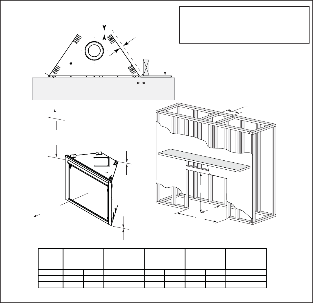
Heatilator • Novus NNXT • 4055-879 • Rev. o • 2/1220
D
Clearance to Ceiling
30 in. (762 mm)
0 in.
0 in. TO LEVEL
OF STANDOFFS
Combustible Object
36 in.
(914 mm)
0 in.
Combustible flooring may be installed next
to the front of the appliance.
Drywall
1/2 in.
(13 mm)
1/2 in.
(13 mm)
C
A
B
Model
in. mm in. mm in. mm in. mm in. mm
NNXT3933 39 991 34 7/8 886 19 5/8 498 10 254 9 229
NNXT4236 42 1067 34 7/ 8 886 19 5/8 498 10 254 9 229
D
Rough Opening
(SLP Pipe)
A
Rough Opening
(Width)
B
Rough Opening
(Height)
D
Rough Opening
(DVP Pipe)
C
Rough Opening
(Depth)
Figure 5.2 Clearances to Combustibles
C. Clearances
NOTICE: Install appliance on hard metal or wood surfaces
extending full width and depth. DO NOT install directly on
carpeting, vinyl, tile or any combustible material other than
wood.
WARNING! Risk of Fire! Maintain specifi ed air space
clearances to appliance and vent pipe:
Note: If the inside of the framed cavity is to be
fi nished, the framing dimensions must include the
fi nished surface. If drywall is to be attached to the
rear wall, the depth must be measured from the
drywall surface.
• Insulation and other materials must be secured to
prevent accidental contact.
• The chase must be properly blocked to prevent blown
insulation or other combustibles from entering and
making contact with fi replace or chimney.
• Failure to maintain airspace may cause overheating and
a fi re.
21Heatilator • Novus NNXT • 4055-879 • Rev. o • 2/12
Measured from top of hood (in inches)
3 4 5 6 7 8 9 10 11 12 13 14 15 16 17
18
5 5-1/2
6-1/4 7 7-3/4
8-1/2
9-1/4 10 10-3/4
11-1/2
12-1/4 13 13-3/4
14-1/2
15-1/4 16
30 in. minimum
to ceiling
D. Mantel and Wall Projections
WARNING! Risk of Fire! Comply with all minimum clear-
ances to combustibles as specifi ed. Framing or fi nishing
material closer than the minimums listed must be construct-
ed entirely of non-combustible materials (i.e., steel studs,
concrete board, etc).
Figure 5.3 Minimum Vertical and Maximum Horizontal Dimensions
Note: All
measurements
in inches.
1 in. (25 mm) min.
to perpendicular wall
A
3-1/2 in. (89 mm) min.
from fireplace opening
to perpendicular wall
B
Mantel Leg or
Perpendicular Wall
Top of
Appliance
Drywall
A
B
Figure 5.4 Mantel Leg or Wall Projections (Acceptable on both sides of opening)
Mantels
Mantel Legs or Wall Projections
Heatilator • Novus NNXT • 4055-879 • Rev. o • 2/1222
Gas, Wood or Fuel Oil
Termination Cap
B
Gas
Termination
Cap **
A *
*If using decorative cap cover(s), this distance may need to be
increased. Refer to the installation instructions supplied with the
decorative cap cover.
**
AB
6 in. (minimum) up to 20 in.
152 mm/508 mm 18 in. minimum
457 mm
20 in. and over 0 in. minimum
In a staggered installation with both gas and wood or fuel oil
terminations, the wood or fuel oil termination cap must be
higher than the gas termination cap.
A. Vent Termination Minimum Clearances
Figure 6.1 Minimum Height From Roof To Lowest Discharge
Opening
Horizontal
overhang
12 X
20 in.
(508 mm)
Lowest
Discharge
Opening
Termination
Cap
Roof Pitch
is X / 12
Vertical
wall
H (min.) - Minimum height
from roof to lowest
discharge opening.
24 in. min.
(610 mm)
Roof Pitch H (Min.) Ft. Roof Pitch H (Min.) Ft.
Flat to 6/12 1.0* Over 11/12 to 12/12 4.0
Over 6/12 to 7/12 1.25* Over 12/12 to 14/12 5.0
Over 7/12 to 8/12 1.5* Over 14/12 to 16/12 6.0
Over 8/12 to 9/12 2.0* Over 16/12 to 18/12 7.0
Over 9/12 to 10/12 2.5 Over 18/12 to 20/12 7.5
Over 10/12 to 11/12 3.25 Over 20/12 to 21/12 8.0
* 3 ft. minimum in snow regions
Storm Collar
Roof
Flashing
6
6 Termination Locations
Fire Risk.
Maintain vent clearance to combustibles as
specifi ed.
• DO NOT pack air space with insulation or other
materials.
Failure to keep insulation or other materials away
from vent pipe may cause overheating and fi re.
WARNING
Figure 6.2 Multiple Termination Caps
23Heatilator • Novus NNXT • 4055-879 • Rev. o • 2/12
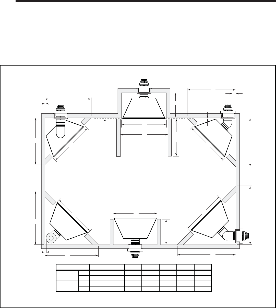
Dimension Descriptions
A Clearance above the ground, a veranda, porch, deck or balcony - 12 in.
(30 cm) minimum. *
B Clearance to window or door that may be opened – 10,000 BTUs or less,
6 in. (15 cm) minimum; 10,000-50,000 BTUs, 9 in. (23 cm) minimum;
over 50,000 BTUs, 12 in. (30 cm) minimum. *
C Clearance to permanently closed window – 12 in. (30 cm) minimum
- recommended to prevent condensation on window.
D Vertical clearance to ventilated soffi t located above the termination within
a horizontal distance of 2 ft (60 cm) from the centerline of the termination
– 18 in. (46 cm) minimum. **
E Vertical clearance to unventilated soffi t - 12 in. (30 cm) minimum. **
F Clearance to outside corner - 6 in. (15 cm) minimum.
G Clearance to inside corner - 6 in. (15 cm) minimum.
H Not to be installed above a meter/regulator assembly within 3 ft (90 cm)
horizontally* from the center line of the regulator (Canada only)
I Clearance to service regulator vent outlet – 3 ft (.91 m) U.S. minimum
and 3 ft (.91 m) Canada minimum. *
J Clearance to non-mechanical air supply inlet into building or the
combustion air inlet to any other appliance – 9” (23 cm) U.S. minimum
and 12 in. (30 cm) Canada minimum. *
K Clearance to mechanical air supply inlet - 3 ft (.91 m) U.S. minimum and
6 ft (1.8 m) Canada minimum. *
L Clearance above a paved sidewalk or paved driveway located on public
property - 7 ft (2.1 m) minimum.
A vent may not terminate directly above a sidewalk or paved driveway
which is located between two single family dwellings and serves both
dwellings.
M Clearance under veranda, porch, deck or balcony - 12 in. (30 cm)
minimum. * Recommended 30 in. (76 cm) for vinyl or plastic.
Only permitted if veranda, porch, deck or balcony is fully open on a
minimum of 2 sides beneath the fl oor. *
N Vertical clearance between two horizontal termination caps – 12 in. (30
cm) minimum.
O Horizontal clearance between two horizontal termination caps – 12 in.
(30 cm) minimum.
P 6” - Non-vinyl sidewalls
12” – Vinyl sidewalls
Q 18” – Non-vinyl soffi t and overhang
42” – Vinyl soffi t and overhang
R 8 ft.
D
E
B
L C
V
V
B
F
V
B V
V
B
X
A
J
Fixed
Closed
M
V K X
RESTRICTION ZONE
(TERMINATION NOT
ALLOWED)
AIR SUPPLY INLET
X
GAS METER
V TERMINATION CAP
H
B
Openable Fixed
Closed
V
I
V
O
N
Q P
R
T
S
E
lectrical
Service
V
U
V U
V
W
D*
V
V
Covered Alcove
Applications Clearances to Electrical Service
A V
V
G
Measure horizontal clearances
from this surface.
Measure vertical clearances
from this surface
S min T max
1 cap 3 ft 2 x S actual
2 caps 6 ft 1 x S actual
3 caps 9 ft 2/3 x S actual
4 caps 12 ft 1/2 x S actual
S min = # term caps x 3 T max = (2/# term caps) x S (actual)
U 6” min. – Clearance from sides of electrical service.
W 12” min. – Clearance above electrical service.
* As specifi ed in CGA B149 Installation Codes
Note: Local codes or regulations may require different clearances.
** Clearance required to vinyl soffi t material – 30 in. (76 cm) minimum.
Note: Location of the vent termination must not interfere with access to
the electrical service.
Figure 6.3 Minimum Clearances for Termination
CAUTION: IF EXTERIOR WALLS ARE FINISHED WITH VINYL SIDING, IT IS SUGGESTED THAT A VINYL PROTECTOR KIT BE INSTALLED.
WARNING!
In the U.S.: Vent system termination is NOT permitted in screened
porches. You must follow side wall, overhang and ground clearances as
stated in the instructions.
In Canada: Vent system termination is NOT permitted in screened
porches. Vent system termination is permitted in porch areas with two
or more sides open. You must follow all side wall, overhang and ground
clearances as stated in the instructions.
Hearth & Home Technologies assumes no responsibility for the improper
performance of the appliance when the venting system does not meet
these requirements.
Heatilator • Novus NNXT • 4055-879 • Rev. o • 2/1224
Horizontal
Vertical
8-1/2 in.
8-1/2 in.
12 in.
On 45° runs, 1 ft (.3 m) of diagonal is equal to 8-1/2 in. (216
mm) horizontal run and 8-1/2 in. (216 mm) vertical run.
A. Approved Pipe
This appliance is approved for use with Hearth & Home
Technologies DVP and/or SLP venting systems. Refer to
Section 17.B. for vent component information.
DO NOT mix pipe, fi ttings or joining methods from differ-
ent manufacturers.
The pipe is tested to be run inside an enclosed wall.
There is no requirement for inspection openings at each
joint within the wall.
WARNING! Risk of Fire or Asphyxiation. This appliance
requires a separate vent. DO NOT vent to a pipe serving a
separate solid fuel burning appliance.
C. Use of Elbows
Diagonal runs have both vertical and horizontal vent as-
pects when calculating the effects. Use the rise for the
vertical aspect and the run for the horizontal aspect (see
Figure 7.1).
Two 45º elbows may be used in place of one 90º elbow.
On 45º runs, one foot of diagonal is equal to 8-1/2 in. (216
mm) horizontal run and 8-1/2 in. (216 mm) vertical run. A
length of straight pipe is allowed between two 45º elbows
(see Figure 7.1).
Figure 7.1 Using Two 45° Elbows
7
7 Vent Information and Diagrams
B. Vent Table Key
The abbreviations listed in this vent table key are used in
the vent diagrams.
D. Measuring Standards
Vertical and horizontal measurements listed in the vent
diagrams were made using the following standards.
• Pipe measurements are shown using the effective length
of pipe (see Figure 7.2).
• Horizontal terminations are measured to the outside
mounting surface (fl ange of termination cap) (see
Figure 6.4.).
• Vertical terminations are measured to bottom of
termination cap.
• Horizontal pipe installed level with no rise.
Figure 7.2 Pipe Effective Length
Symbol Description
V1First section (closest to appliance) of vertical length
V2Second section of vertical length
H1First section (closest to appliance) of horizontal length
H2Subsequent sections of horizontal length
Effective
Height/Length
DVP Pipe
(see chart)
Pipe inches mm
DVP4 4 102
DVP6 6 152
DVP12 12 305
DVP24 24 610
DVP36 36 914
DVP48 48 1219
DVP6A 3 - 6 76 - 152
DVP12A 3 - 12 76 - 305
Effective Height/Length
SLP Pipe
(see chart)
Pipe inches mm
SLP4 4 102
SLP6 6 152
SLP12 12 305
SLP24 24 610
SLP36 36 914
SLP48 48 1219
SLP6A 2 - 6 51 - 152
SLP12A 2 - 12 51 - 305
Effective Height/Length
Effective
Height/Length
25Heatilator • Novus NNXT • 4055-879 • Rev. o • 2/12
H1
V1
To replace the fi rst starter elbow with two 45° elbows,
refer to Figure 7.4. All other 90° elbows can be replaced
with two 45° elbows.
General Rules:
• SUBTRACT 3 ft. from the total H measurement for each
90° elbow installed horizontally.
• SUBTRACT 1-1/2 ft. from the total H measurement for
each 45° elbow installed horizontally.
• A maximum of three 90° elbows (or six 45° elbows)
may be used in any vent confi guration. Some elbows
may be installed horizontally. See Figure 7.8.
• Elbows may be placed back to back anywhere in the
system as long as the fi rst 90° elbow is a starter elbow
except as shown in Figure 7.4.
• When penetrating a combustible wall, a wall shield
fi restop must be installed.
• When penetrating a combustible ceiling, a ceiling
fi restop must be installed.
• Horizontal runs of vent do not require vertical rise;
horizontal runs may be level.
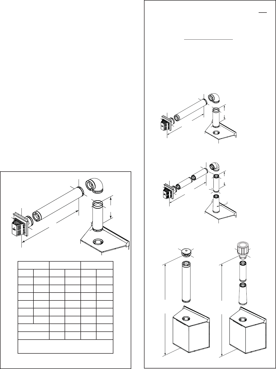
E. Vent Diagrams
Figure 7.3
One Elbow
1. Top Vent - Horizontal Termination
Note: The NNXT series appliances can adapt to
SLP series vent pipe when venting off the top of
the appliance. You must use a DVP-SLP24 adapter
which can only be attached to the appliance starting
collar.
When looking at horizontal termination diagrams, the
adapter is not counted as part of the minimum vertical
(V1 min.) requirements.
Whether horizontal or vertical termination, the adapter is
counted as part of the maximum vertical limitations.
All venting rules for the vent run must still be followed.
H1 = 11 ft.
max.
V1 = 1 ft.
DVP-SLP24
H1 = 11 ft.
max
V1 = 1 ft.
DVP
HORIZONTAL EXAMPLE
SLP
12 ft (3.66 m) min.
60 ft (18.29 m) max. 12 ft (3.66 m) min.
60 ft (18.29 m) max.
DVP
VERTICAL EXAMPLE
SLP
DVP-SLP24
Adapter
V1 min. V1 max. H1 max.
ft m ft m ft m
0 0.00 - - 2 0.61
0.33 0.10 - - 4 1.22
0.5 0.15 - - 6 1.83
1 0.30 - - 11 3.35
1.5 0.46 - - 17 5.18
2 0.61 - - 17 5.18
DVP 25 7.62 17 5.18
SLP 23 7.01 17 5.18
You may install the elbow directly on top
of the appliance (DVP only).
Heatilator • Novus NNXT • 4055-879 • Rev. o • 2/1226
4 ft min.
(1.22 m)
17 ft max.
(5.18 m)
H1V1
H2
H3
Installed
Horizontally
Installed
Vertically
H2
Figure 7.5
Two Elbows
1. Top Vent - Horizontal Termination - (continued)
Figure 7.4
Two 45° Elbows replacing One 90° Elbow
V1 min. V1 max. H1+H2 max. H1+H2+H3 max.
ft m ft m ft m ft m
0.5 0.15 - - 6 1.83 - -
1 0.30 - - 11 3.35 11 3.35
1.5 0.46 - - 17 5.18 17 5.18
2 0.61 - - 17 5.18 17 5.18
DVP 25 7.62 17 5.18 17 5.18
SLP 23 7.01 17 5.18 17 5.18
27Heatilator • Novus NNXT • 4055-879 • Rev. o • 2/12
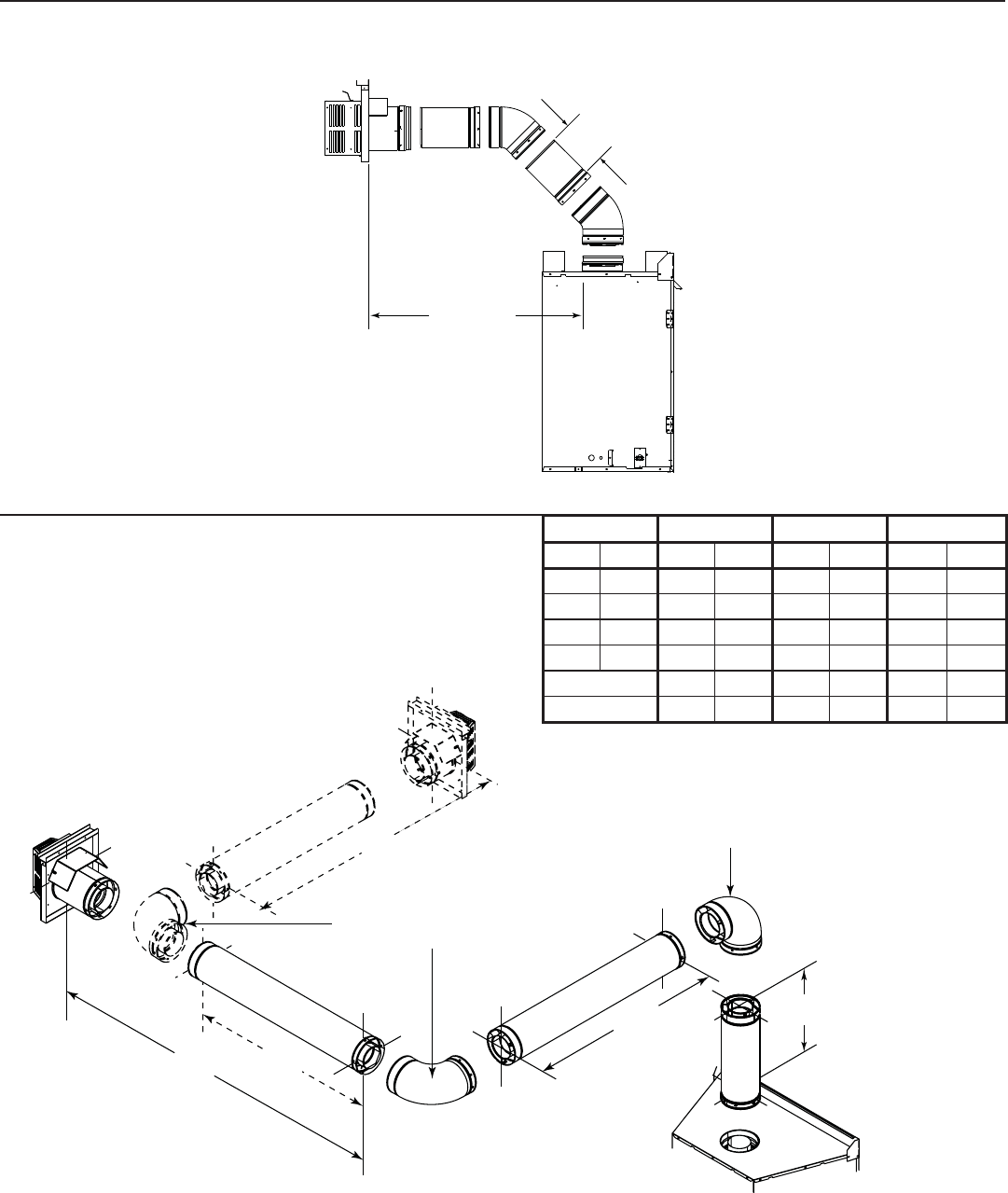
Figure 7.6
1. Top Vent - Horizontal Termination - (continued)
Three Elbows
H1
V1
V2
H2
Installed
Vertically
V1 min. V1 + V2 max. H1+H2 max.
ft m ft m ft m
DVP 1 0.30 24 7.32 17 5.18
SLP 1 0.30 22 6.71 17 5.18
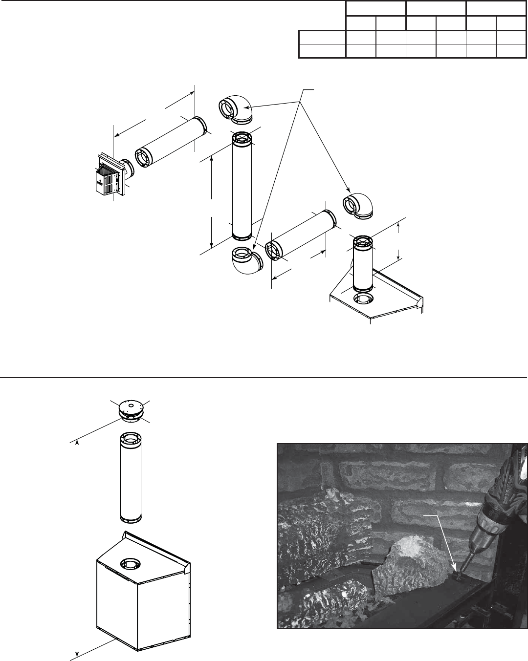
2. Top Vent - Vertical Termination
No Elbow
Figure 7.7
12 ft (3.66 m) min.
60 ft (18.29 m) max.
Install Top Vent Flue Visor - No Elbow Confi gura-
tions
• Remove the refractory retainer from one side
refractory.
Remove lower
refractory retainer
Figure 7.7a Remove Refractory Retainer from one Side
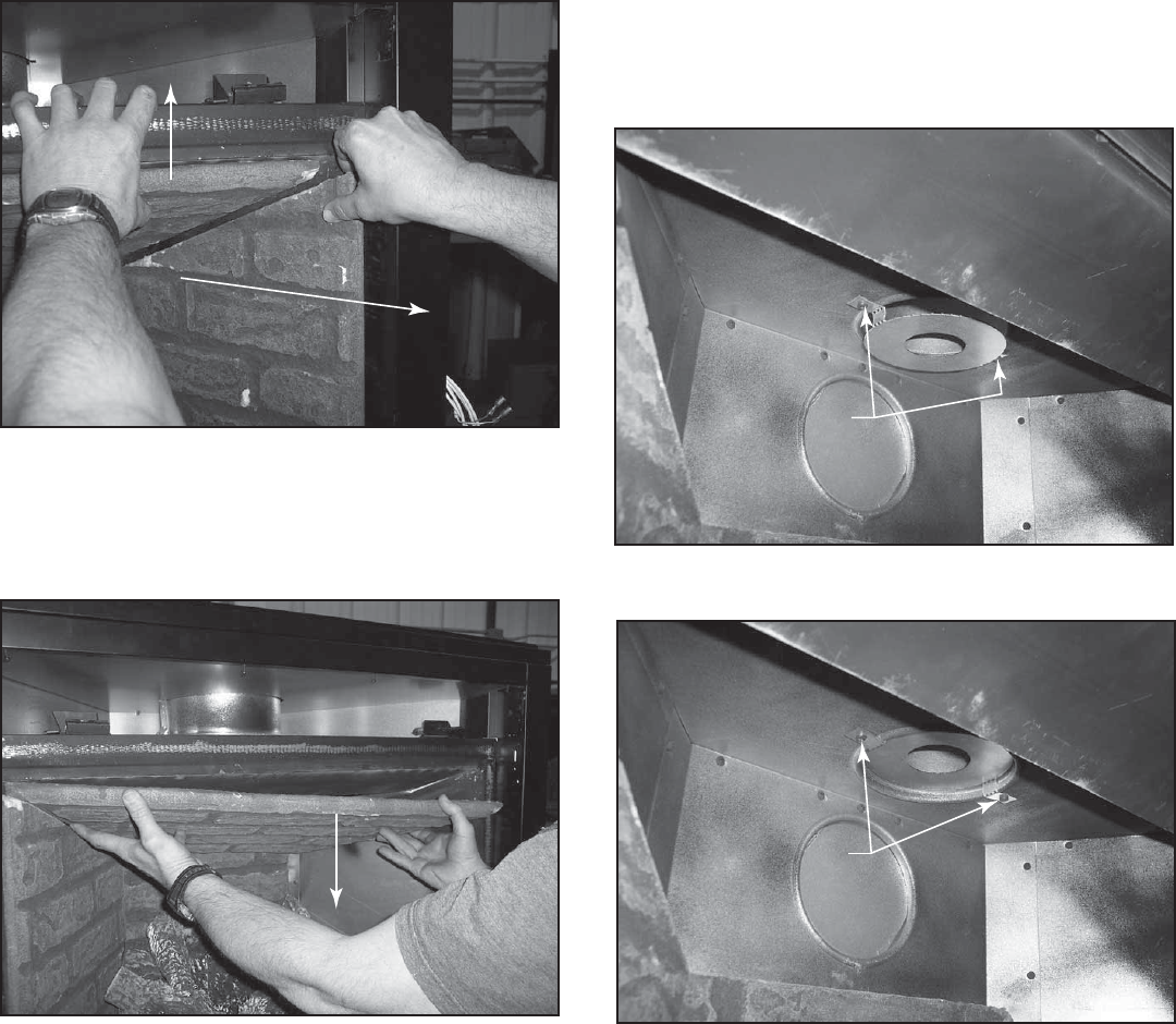
Heatilator • Novus NNXT • 4055-879 • Rev. o • 2/1228
Lift top refractory
and hold in place
Pull side refractory
forward & out
Figure 7.7b Remove Side Refractory
• Remove the side refractory:
- Gently raise the front of the top refractory.
- Lift the side piece up slightly and then out.
• Remove top refractory:
- Lower towards side removed in previous step.
- Gently twist out.
Lower & twist; pull out
Figure 7.7c Remove Top Refractory
• Remove two screws from fi rebox top.
• Using these screws and the same holes, install the top
vent fl ue baffl e.
- The fl ue baffl e will be turned to install below the level
of the fi rebox top for 12-30 ft vertical runs of vent.
See Figure 7.7d.
- The fl ue baffl e will be turned to install inside the fl ue
for vertical vent runs of 31-60 ft. See Figure 7.7e.
Figure 7.7d 12-30 ft Vertical Run
Figure 7.7e 31-60 ft Vertical Run
Place flue visor,
reinsert screws
Place flue visor,
reinsert screws
• Reinstall Refractory:
- Replace top refractory.
- Lift top refractory and slide side refractory back into
position.
- Replace bottom retainer.
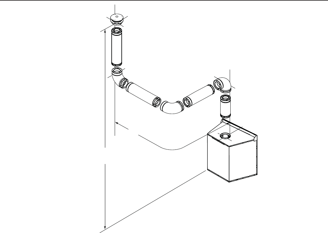
29Heatilator • Novus NNXT • 4055-879 • Rev. o • 2/12
Figure 7.8
2. Top Vent - Vertical Termination - (continued)
Three Elbows
12 ft (3.66 m) min.
60 ft (18.29 m) max.
Maximum horizontal run is
100% of vertical, but cannot
exceed 17 ft (5.18 m)
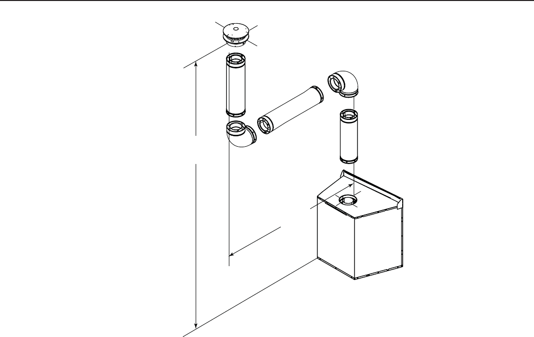
Heatilator • Novus NNXT • 4055-879 • Rev. o • 2/1230
Figure 7.9
Two Elbows
12 ft (3.66 m) min.
60 ft (18.29 m) max.
Maximum horizontal
run is 100% of
vertical, but cannot
exceed 17 ft (5.18 m)
2. Top Vent - Vertical Termination - (continued)
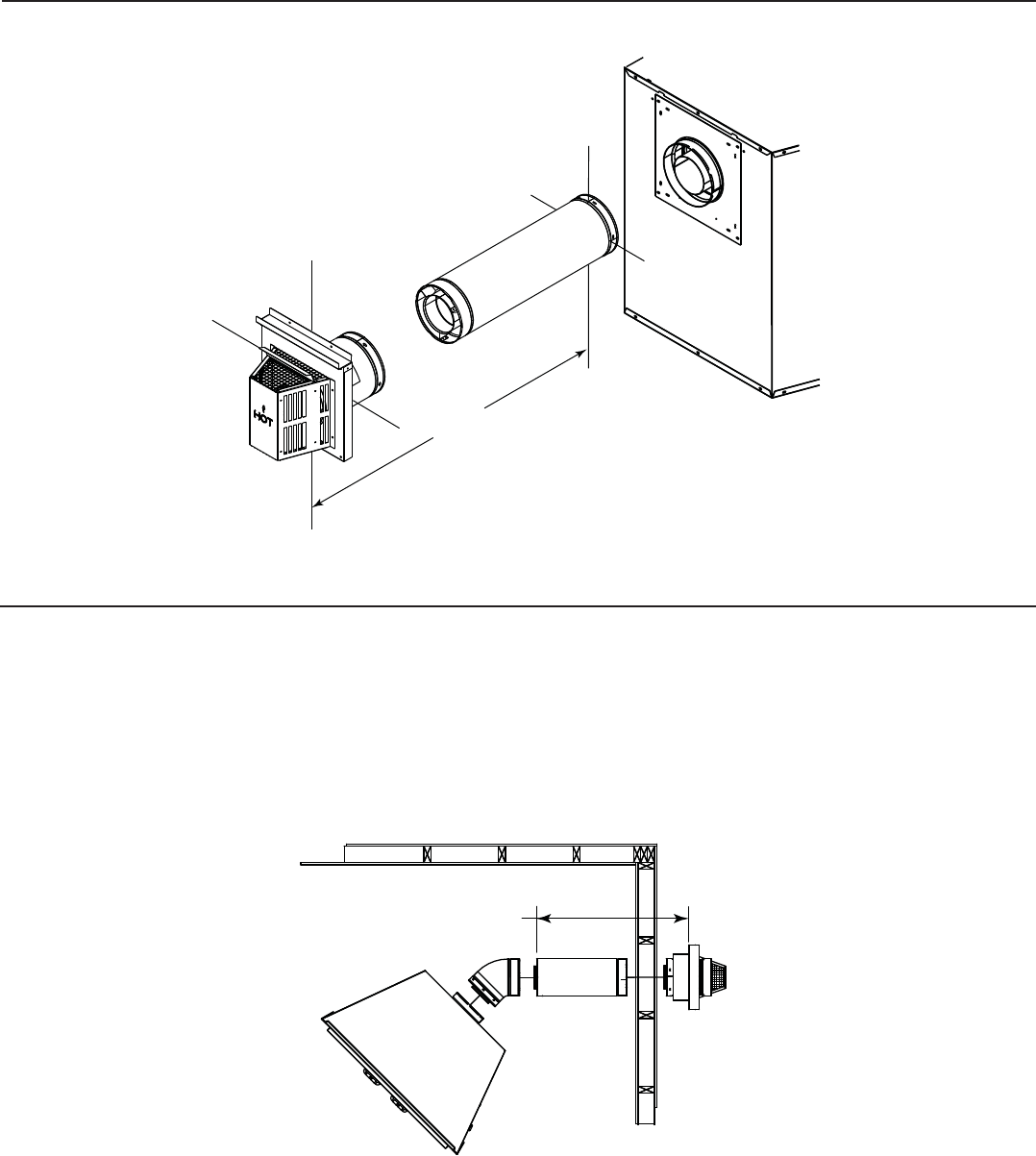
31Heatilator • Novus NNXT • 4055-879 • Rev. o • 2/12
3. Rear Vent - Horizontal Termination
Figure 7.10
Figure 7.11
No Elbow
One 45° Elbow
18 in. (457 mm) max.
18 in. (457 mm) max.
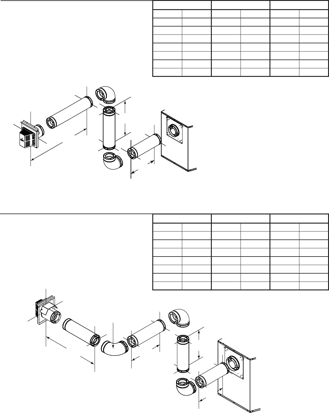
Heatilator • Novus NNXT • 4055-879 • Rev. o • 2/1232
3. Rear Vent - Horizontal Termination - (continued)
Two Elbows
Figure 7.12
Figure 7.13
Three Elbows
H2
V1
H1
H2
V1
H3
H1
Installed
Horizontally
H1 max. V1 min. H1+H2+H3 max.
ft m ft m ft m
0 0 1 0.30 3 0.91
2 0.61 1 0.30 3 0.91
4 1.22 2 0.61 6 1.83
6 1.83 3 0.91 9 2.74
8 2.44 4 1.22 12 3.66
8 2.44 5 1.52 15 4.57
8 2.44 6 1.83 18 5.49
H1 max. V1 min. H1+H2 max.
ft m ft m ft m
0 0 1 0.30 3 0.91
2 0.61 1 0.30 3 0.91
4 1.22 2 0.61 6 1.83
6 1.83 3 0.91 9 2.74
8 2.44 4 1.22 12 3.66
8 2.44 5 1.52 15 4.57
8 2.44 6 1.83 18 5.49
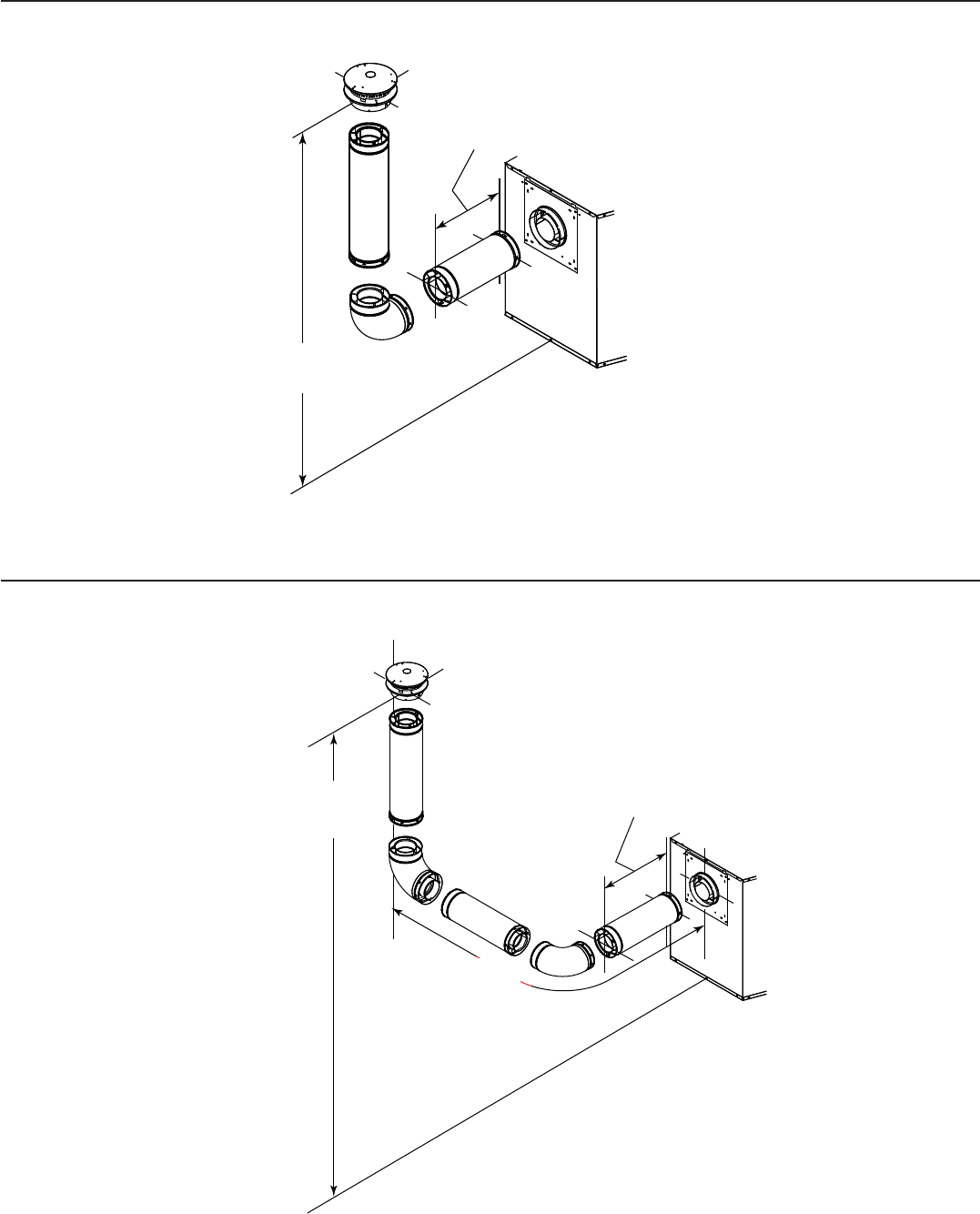
33Heatilator • Novus NNXT • 4055-879 • Rev. o • 2/12
4. Rear Vent - Vertical Termination
One Elbow
Figure 7.14
Two Elbows
Figure 7.15
12 ft (3.66 m) min.
60 ft (18.29 m) max.
0 min.
6 ft (1.83 m) max.
12 ft (3.66 m) min.
60 ft (18.29 m) max.
0 min.
6 ft (1.83 m) max.
Maximum horizontal
run is 100% of
vertical, but cannot
exceed 18 ft (5.49 m)
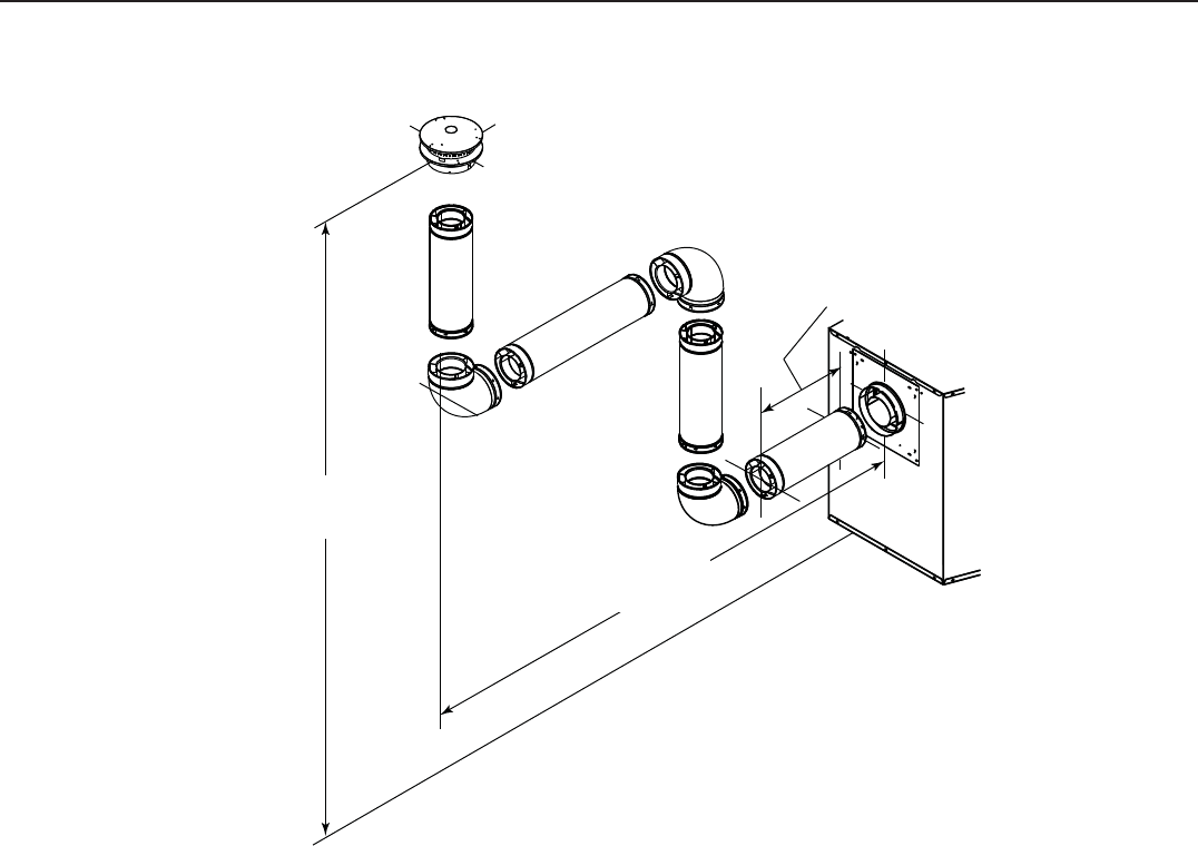
Heatilator • Novus NNXT • 4055-879 • Rev. o • 2/1234
4. Rear Vent - Vertical Termination - (continued)
Three Elbows
Figure 7.16
12 ft (3.66 m) min.
60 ft (18.29 m) max.
0 min.
6 ft (1.83 m) max.
Maximum horizontal run is
100% of vertical, but can-
not exceed 18 ft (5.49 m)
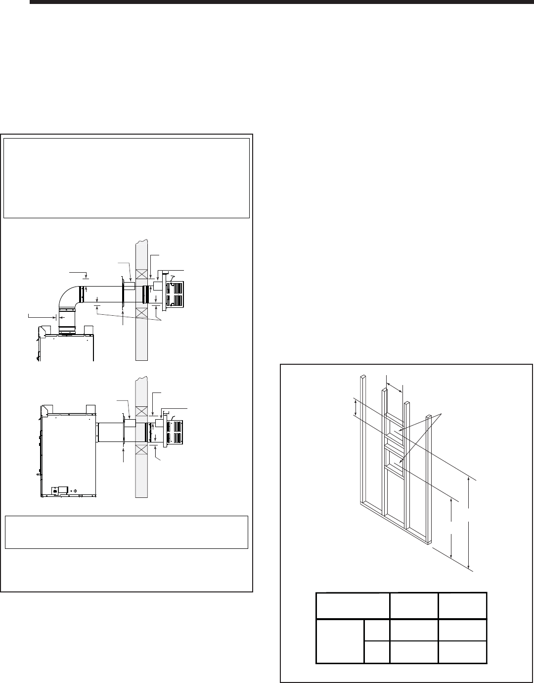
35Heatilator • Novus NNXT • 4055-879 • Rev. o • 2/12
* When using SLP pipe, minimum clearances from the vent pipe to combustible materi-
als at inside wall firestops are: Top: 2-1/2 in. (64 mm)
Bottom: 1/2 in. (13 mm)
Sides: 1 in. (25 mm)
Note: Heat shields MUST overlap by a minimum of 1-1/2 in. (38 mm).
• DVP heat shield - designed to be used on a wall 4 in. to 7-1/4 in. (102 mm to 184
mm) thick.
• If wall thickness is less than 4 in. the existing heat shields must be field trimmed.
If wall thickness is greater than 7-1/4 in. an extended heat shield will be required.
• SLP heat shield - designed to be used on a wall 4-3/8 in. to 7-5/8 in. (111 mm to 194
mm thick).
• If wall thickness is less than 4-3/8 the existing heat shields must be field trimmed.
If wall thickness is greater than 7-5/8 in. an extended heat shield will be required.
3 in. (76 mm)
top clearance *
1 in. (25 mm)
clearance
bottom & sides
Heat
Shield
Wall
Shield
Firestop
Heat
Shield
WALL
3 in. (76 mm)
top clearance *
1 in. (25 mm)
clearance
bottom & sides
Heat
Shield
Wall
Shield
Firestop
Heat
Shield
WALL
3 in. (76 mm)
top clearance
1 in. (25 mm)
clearance around
vertical sections
(DVP Pipe Shown)
B*
Framing should be
constructed of 2 X 4
lumber or heavier.
The center of the
framing hole is
1 in. (25mm) above
the center of the
horizontal vent pipe.
A*
Vent framing hole.
DO NOT PACK WITH
INSULATION OR
OTHER MATERIAL.
* To center of pipe.
10 in.
12 in.
A
Top Vent
B
Rear Vent
1003
597
23-1/2
39-1/2
Model
mm
in.
NNXT4236
NNXT3933
A. Pipe Clearances to Combustibles
WARNING! Risk of Fire! Maintain air space clearance to
vent. DO NOT pack insulation or other combustibles:
• Between ceiling fi restops
• Between wall shield fi restops
• Around vent system
Failure to keep insulation or other material away from
vent pipe may cause over heating and fi re.
8
8 Vent Clearances and Framing
B. Wall Penetration Framing
Combustible Wall Penetration
Whenever a combustible wall is penetrated, you must
frame a hole for the wall shield fi restop(s). The wall shield
fi restop maintains minimum clearances and prevents cold
air infi ltration.
• The opening must be framed on all four sides using the
same size framing materials as those used in the wall
construction.
• SLP pipe - A wall shield fi restop must be placed on each
side of an interior wall. A minimum 1 1/2 in. (38 mm)
overlap of attached heat shields must be maintained.
• DVP pipe - A wall shield fi restop is required on one side
only on interior walls. If your local inspector requires a
wall shield fi restop on both sides, then both wall shield
fi restops must have a heat shield attached to them.
• See Section 10.L. for information for regarding the
installation of a horizontal termination cap.
Figure 8.2 Wall Penetration
Figure 8.1 Horizontal Venting Clearances To Combustible
Materials
Non-Combustible Wall Penetration
If the hole being penetrated is surrounded by non-combus-
tible materials such as concrete, a hole with diameter one
inch greater than the pipe is acceptable.
Whenever a non-combustible wall is penetrated, the wall
shield fi restop is only required on one side and no heat
shield is necessary.
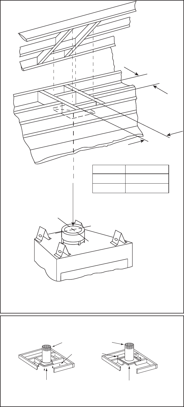
Heatilator • Novus NNXT • 4055-879 • Rev. o • 2/1236
3 fasteners
per side
Ceiling firestop
installed below ceiling. Ceiling firestop
installed above ceiling.
Install attic insula-
tion shields before
or after installation
of vent system.
ATTIC ABOVE
A
PIPE
DVP
SLP
A
10 in. (254 mm)
9 in. (229 mm)
A
C. Install the Ceiling Firestop
A ceiling fi restop MUST be used between
fl oors and attics.
• DVP pipe only - Frame an opening 10 in.
by 10 in. (254 mm by 254 mm) whenever
the vent penetrates a ceiling/fl oor (see
Figure 8.3).
• SLP pipe only - Frame opening 9 in. x
9 in. (229 mm x 229 mm) whenever the
vent penetrates a ceiling/floor (see Figure
8.3).
• Frame the area with the same sized lumber
as used in ceiling/fl oor joist.
• The ceiling fi restop may be installed above
or below the ceiling joists when installed
with a attic insulation shield. It must be
under joists between fl oors that are not
insulated. Refer to Figure 8.4.
• Secure with three fasteners on each side.
Figure 8.3 Installing Ceiling Firestop
Figure 8.4 Installing the Attic Shield
WARNING! Risk of Fire! DO NOT pack insu-
lation around the vent. Insulation must be kept
back from the pipe to prevent overheating.
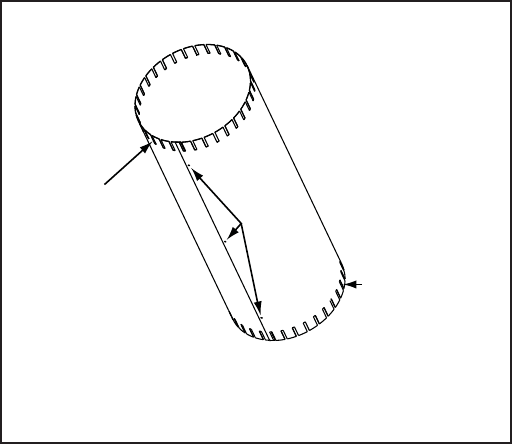
37Heatilator • Novus NNXT • 4055-879 • Rev. o • 2/12
Bend all tabs inward
90° to maintain
clearance and
prevent insulation
from falling inside
Insert 3
screws
Bend 4 tabs
inward 90°
to maintain
clearance
D. Install Attic Insulation Shield
WARNING! Fire Risk. DO NOT allow loose materials or
insulation to touch vent. Hearth & Home Technologies Inc.
requires the use of an attic shield.
The National Fuel Gas Code ANSI Z223.1 and NFPA 54
requires an attic shield constructed of 26 gauge minimum
metal that extends at least 2 in. (51 mm) above insulation.
Attic shields must meet specifi ed clearance and be se-
cured in place.
Flat Ceiling Installation
• Remove one shield from box.
NOTICE: Cut previously installed batt insulation to make
room for the attic insulation shield.
• Wrap shield around pipe if pipe is already installed in
area to be insulated.
• Match the three holes in each side and fasten with three
screws to form a tube.
• Bend three tabs on the bottom of the shield outward to
allow attachment to the ceiling fi restop.
• Bend the remaining bottom tabs inward 90° to maintain
the air space between the pipe and the shield. Set the
shield on the ceiling fi restop and attach to the fi restop.
• Bend all tabs inward 90° around the top of the shield.
These tabs must be used to prevent blown insulation
from getting between the shield and vent pipe, and to
maintain air space clearance.
Figure 8.5 Attic Insulation Shield
Vaulted Ceiling Installation
• Remove one shield from box.
NOTICE: Cut previously installed batt insulation to make
room for the attic insulation shield.
• Cut the attic insulation shield (if application is for vaulted
ceiling) to fi t your ceiling pitch. Snip cut edge to recreate
1 in. bend tabs all the way around the bottom.
• Wrap shield around pipe if pipe is already installed in
area to be insulated.
• Match the three holes in each side and fasten with three
screws to form a tube.
• Bend three tabs on the bottom of the shield outward to
allow attachment to the ceiling fi restop.
• Bend the remaining bottom tabs inward 90° to maintain
the air space between the pipe and the shield. Set
the shield on the ceiling fi restop and attach to the
fi restop.
• Bend all tabs inward 90° around the top of the shield.
These tabs must be used to prevent blown insulation
from getting between the shield and vent pipe, and to
maintain air space clearance.
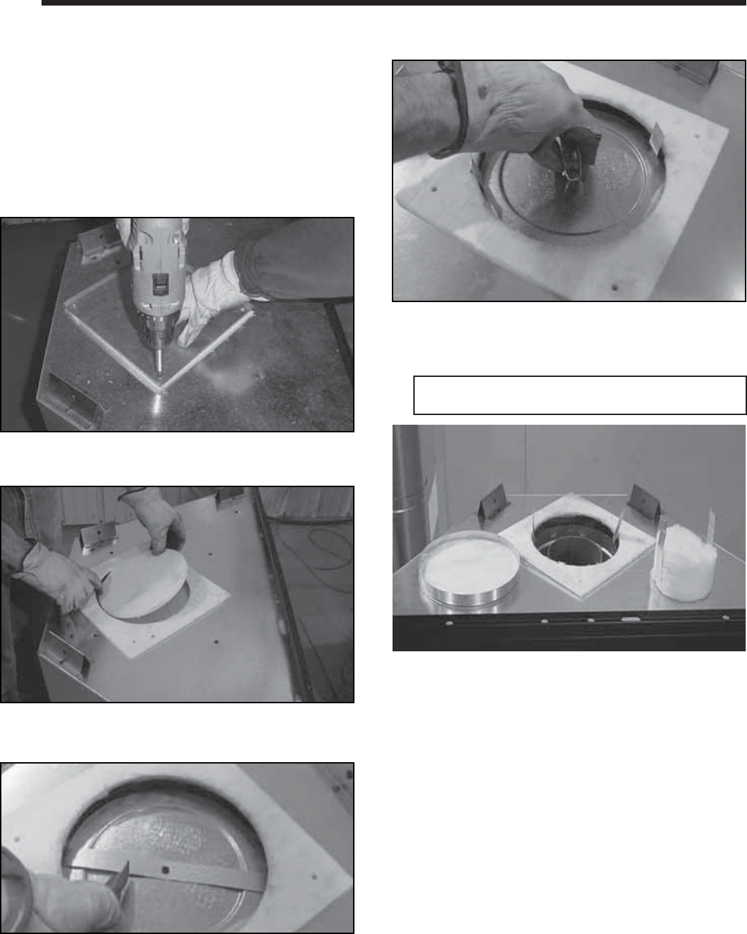
Heatilator • Novus NNXT • 4055-879 • Rev. o • 2/1238
CAUTION! Risk of Cuts, Abrasions or Flying Debris.
Wear protective gloves and safety glasses during installa-
tion. Sheet metal edges are sharp.
NOTICE: Once appliance is set up for top or rear venting,
it CANNOT be changed at a later time.
A. Top Vent
9
9 Appliance Preparation
Figure 9.1
Figure 9.2
Figure 9.3
Figure 9.4
Figure 9.5
• Discard the vent cap, remove and discard the insulation
basket.
Note: Once the vent cap has been removed it cannot
be reattached.
• Fold the center parts of the retaining band up and use
to remove the vent cap.
• Remove the cover plate by removing the four screws
holding it to the top of the appliance. Remove and discard
the cover plate.
• Remove the center insulation plug.
• Cut the metal retaining band and fold the sides out.
• Snap the fi rst vent section into place.
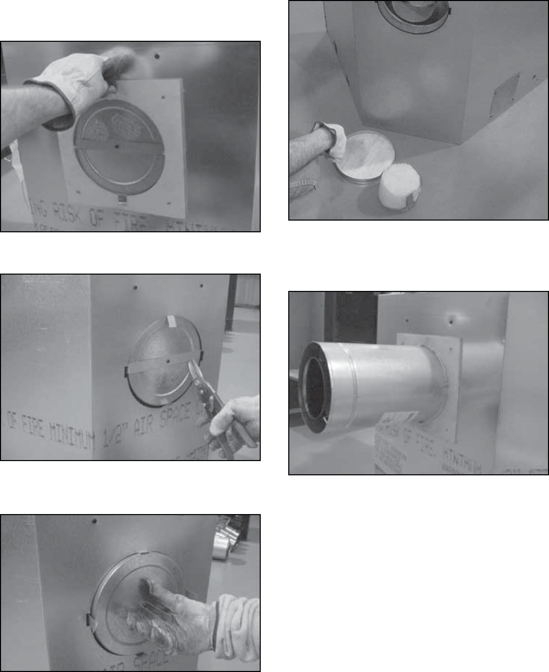
39Heatilator • Novus NNXT • 4055-879 • Rev. o • 2/12
B. Rear Vent
NOTICE: Once appliance is set up for top or rear venting,
it CANNOT be changed at a later time.
Figure 9.6
Figure 9.8
Figure 9.7
Figure 9.10
Figure 9.9
• Fold the tabs toward the center of the vent cap (90º) and
remove the insulation gasket.
• Cut the metal retaining band and fold the sides out.
• Fold the center parts of the retaining band out and use
to remove the vent cap.
• Discard the vent cap, remove and discard the insulation
basket.
• Attach the fi rst vent section (it will snap into place). Slide
the insulation gasket onto the vent section, up against
the appliance and over the tabs.
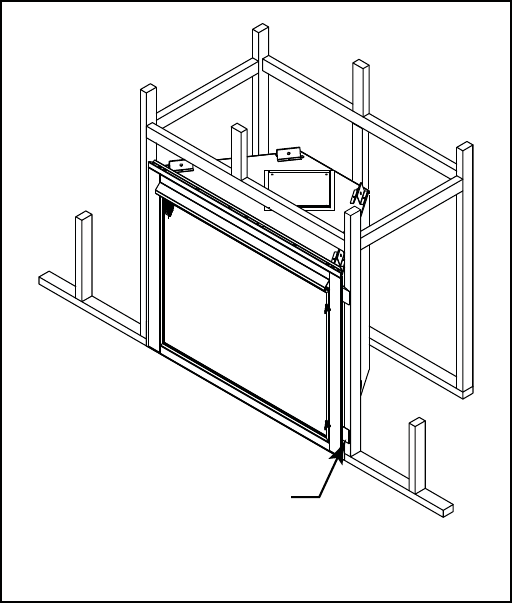
Heatilator • Novus NNXT • 4055-879 • Rev. o • 2/1240
Nailing Flanges
(both sides)
C. Secure and Level the Appliance
WARNING! Risk of Fire! Prevent contact with:
• Sagging or loose insulation
• Insulation backing or plastic
• Framing and other combustible materials
Block openings into the chase to prevent entry of
blown-in insulation. Make sure insulation and other
materials are secured.
DO NOT notch the framing around the appliance
standoffs.
Failure to maintain air space clearance may cause
overheating and fi re.
The diagram shows how to properly position and secure
the appliance (see Figure 9.11). Nailing tabs are provided
to secure the appliance to the framing members.
• Bend out nailing tabs on each side.
• Place the appliance into position.
• Keep nailing tabs fl ush with the framing.
• Level the appliance from side to side and front to
back.
• Shim the appliance as necessary. It is acceptable to use
wood shims underneath the appliance.
• Secure the appliance to the framing by using nails or
screws through the nailing tabs.
• Secure the appliance to the fl oor by inserting two screws
through the pilot holes at the bottom of the appliance.
Figure 9.11 Proper Positioning and Securing of an Appliance
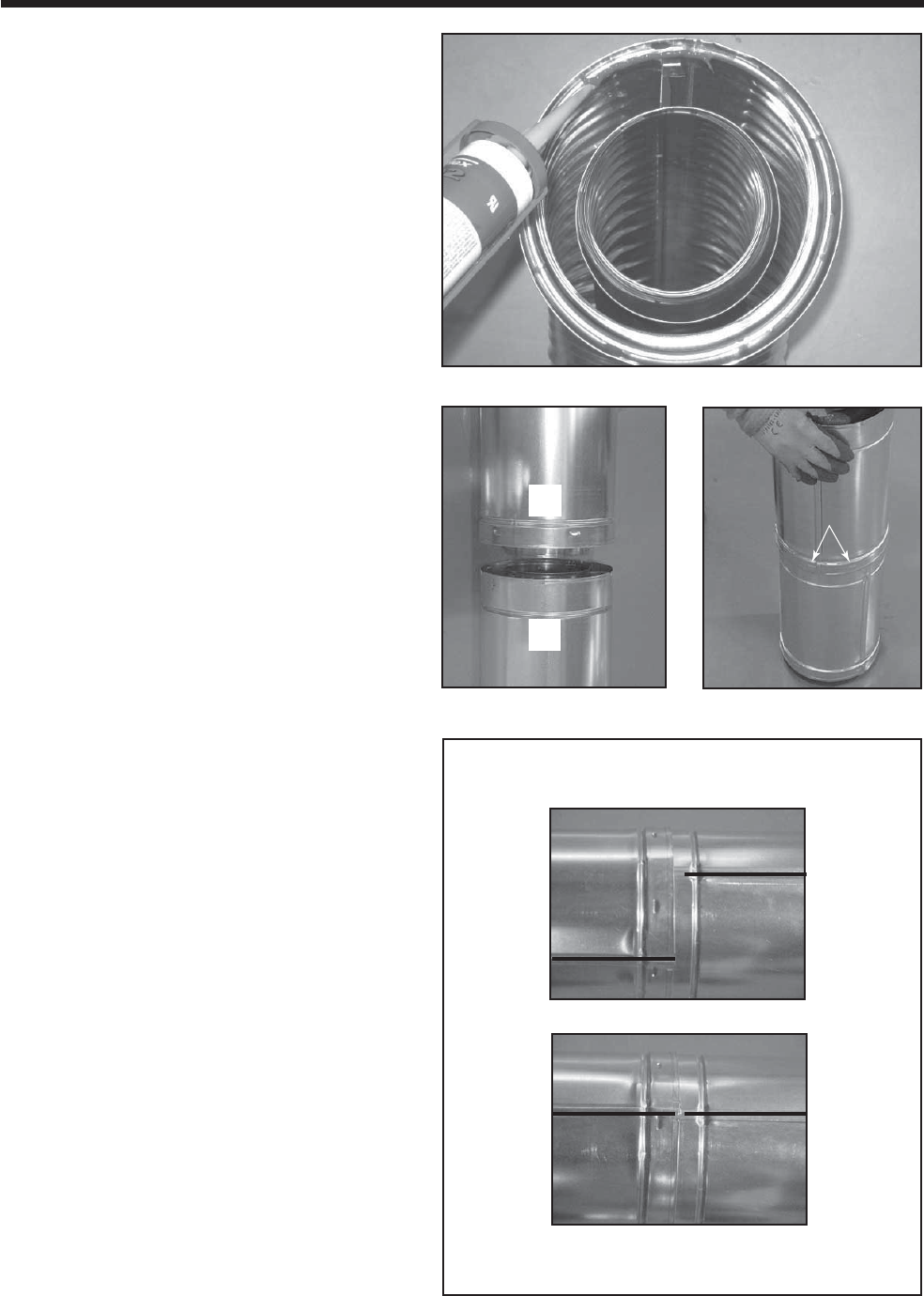
41Heatilator • Novus NNXT • 4055-879 • Rev. o • 2/12
Lances
10
10 Install Vent Pipe
A. Assemble Vent Sections (DVP Only)
Attach Pipe to the Firebox Assembly
Note: The end of the pipe sections with the lanced tabs will
face towards the appliance.
Attach the fi rst pipe section to the starting collar:
• Lanced pipe end to the starting collar
• Inner pipe over inner collar
• Push the pipe section until all lanced tabs snap in
place
• Lightly tug on pipe to confi rm it has locked.
Figure 10.1 High Temperature Silicone Sealant
Figure 10.2 Figure 10.3
Assemble Pipe Sections
Per Figure 10.2:
• Start the inner pipe on the lanced end of section A into
the fl ared end of section B.
• Start the outer pipe of section A over the outer pipe of
section B.
• Once both vents sections are started, push fi rmly until
all lanced tabs lock into place.
• Lightly tug on the pipe to confirm the tabs have
locked.
It is acceptable to use screws no longer than 1/2 in. (13
mm) to hold outer pipe sections together. If predrilling
holes, DO NOT penetrate inner pipe.
For 90° and 45° elbows that are changing the vent
direction from horizontal to vertical, one screw minimum
should be put in the outer fl ue at the horizontal elbow joint
to prevent the elbow from rotating. Use screws no longer
than 1/2 in. (13 mm). If predrilling screw holes, DO NOT
penetrate inner pipe.
Commercial, Multi-family (Multi-level exceeding
two stories), or High-Rise Applications
All outer pipe joints must be sealed with high temperature
silicone with a minimum of 300ºF continuous exposure
rating, including the slip section that connects directly to
the horizontal termination cap.
• Apply a bead of silicone sealant inside the female outer
pipe joint prior to joining sections. See Figure 10.1
• Only outer pipes need to be sealed. All unit collar, pipe,
slip section, elbow and cap outer fl ues shall be sealed in
this manner, unless otherwise stated.
WARNING! Risk of Fire or Explosion! DO NOT break
silicone seals on slip sections. Use care when removing
termination cap from slip pipe. If slip section seals are bro-
ken during removal of the termination cap, vent may leak.
Figure 10.4 Seams
Note: Make sure that the seams are not aligned to prevent
unintentional disconnection.
A
B
INCORRECT
CORRECT
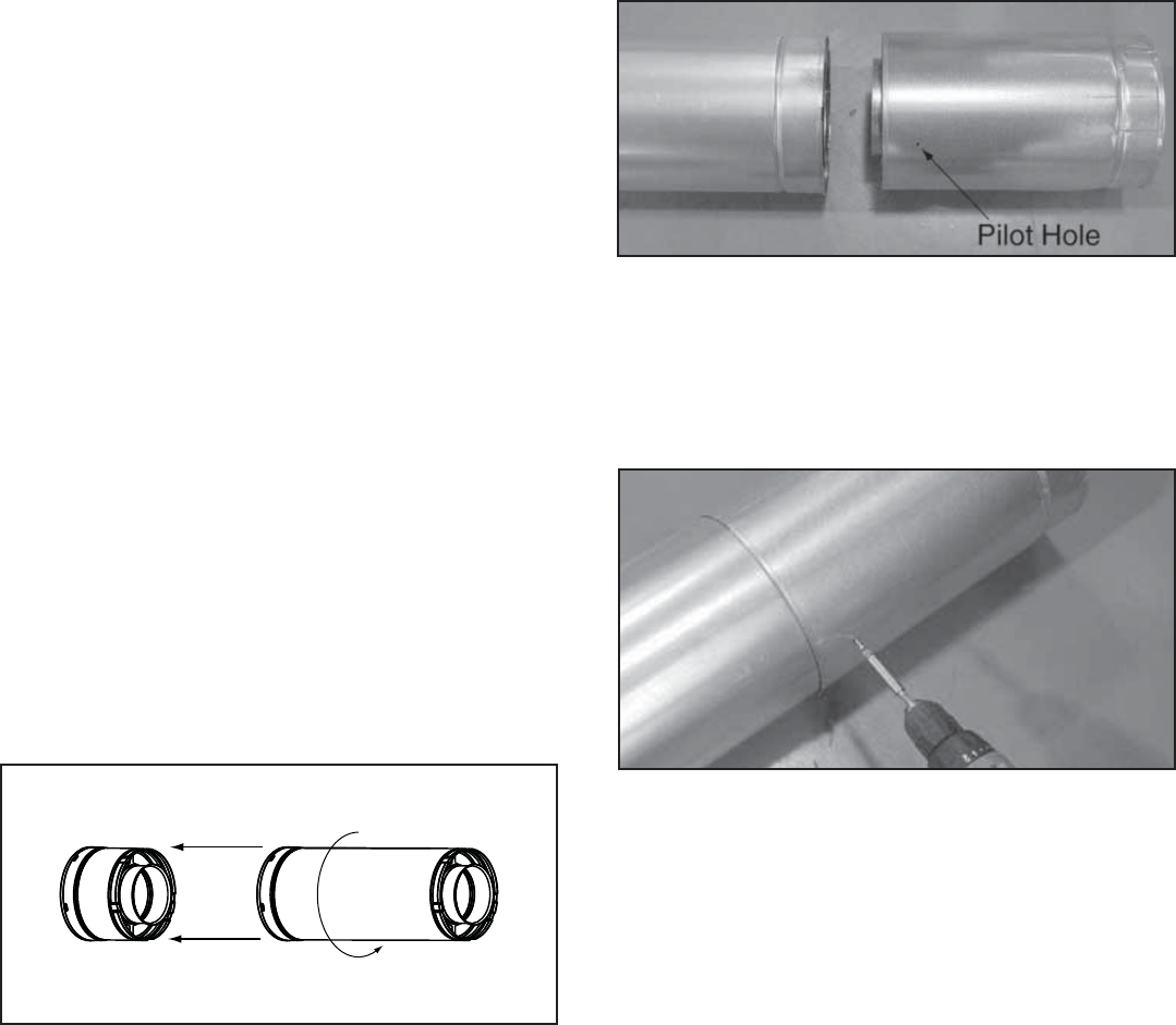
Heatilator • Novus NNXT • 4055-879 • Rev. o • 2/1242
B. Assemble Vent Sections (SLP Only)
To attach the fi rst vent component to the starting collars
of the appliance
• Attach a DVP-SLP24 adapter to the starting collar of the
appliance.
• Lock the vent components into place by sliding the pipe
section onto the collar.
• Align the seam of the pipe and seam of collar to allow
engagement. Rotate the vent component to lock into
place. Use this procedure for all vent components. See
Figure 10.5.
• Slide the gasket over the fi rst vent section and place
it flush to the appliance. This will prevent cold air
infi ltration. Caulk with a minimum of 300ºF continuous
exposure rating may be used to hold the part in place.
• Continue adding vent components, locking each
succeeding component into place.
• Ensure that each succeeding vent component is securely
fi tted and locked into the preceding component.
1 - Align Seams
2 - Rotate
Figure 10.5 Adding Venting Components
WARNING! Risk of Fire or Explosion! DO NOT break
silicone seals on slip sections. Use care when removing
termination cap from slip pipe. If slip section seals are bro-
ken during removal of the termination cap, vent may leak.
Commercial, Multi-family (Multi-level exceeding
two stories), or High-Rise Applications
For Installation into a commercial, multi-family (multi-level
exceeding two stories) or high-rise applications: All outer
pipe joints must be sealed with silicone with a minimum
of 300ºF continuous exposure rating, including the slip
section that connects directly to the horizontal termination
cap.
• Apply a bead of silicone sealant inside the female outer
pipe joint prior to joining sections. See Figure 10.1
• Only outer pipes need to be sealed. All unit collar, pipe,
slip section, elbow and cap outer fl ues shall be sealed
in this manner, unless otherwise stated.
C. Assemble Slip Sections
WARNING! Risk of Fire or Asphyxiation! Overlap pipe
sections at least 1 1/2 in. (38 mm). Secure slip sections
with two screws which must not exceed 1/2 in. (13 mm)
in length. Use the pilot holes. Pipe could separate if not
properly joined.
• Slide the inner fl ue of the slip section into the inner fl ue of
the pipe section and the outer fl ue of the slip section over
the outer fl ue of the pipe section. See Figure 10.6.
• Slide together to the desired length.
Figure 10.6 Slip Section Pilot Holes
Figure 10.7 Screws into Slip Section
NOTICE: When installing a vent system with an HRC
termination cap, all pipe system joints shall be sealed using
silicone with a minimum of 300ºF continuous exposure
rating.
• Apply a bead of silicone sealant inside the female outer
pipe joint prior to joining sections.
• Only outer pipes are sealed, sealing the inner fl ue is not
required.
• All unit collar, pipe, slip section, elbow and cap outer fl ues
shall be sealed.
• Continue adding pipe as necessary following instructions
in “Assemble Pipe Sections.”
NOTICE: If slip section is too long, the inner and outer fl ues
of the slip section can be cut to the desired length.
• Maintain a 1-1/2 in. (38 mm) overlap between the slip
section and the pipe section.
• Secure the pipe and slip section with two screws no
longer than 1/2 in. (13 mm), using the pilot holes in the
slip section. See Figure 10.7.
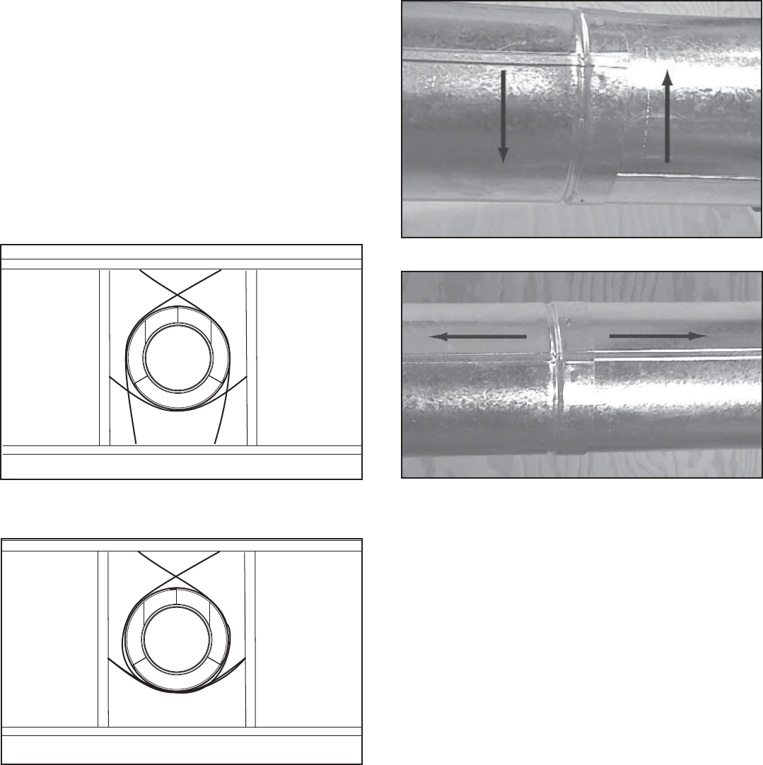
43Heatilator • Novus NNXT • 4055-879 • Rev. o • 2/12
Figure 10.8 Securing Vertical Pipe Sections
Figure 10.9 Securing Horizontal Pipe Sections
E. Disassemble Vent Sections
• Rotate either section (see Figure 10.10) so the seams
on both pipe sections are aligned as shown in Figure
10.11.
• Pull carefully to separate the pieces of pipe.
D. Secure the Vent Sections
• Vertical runs of DVP pipe must be supported every 8 ft.
(2.44 m) after the 25 ft. (7.62 m) maximum unsupported
rise.
• Vertical runs of SLP pipe must be supported every 8 ft.
(2.44 m).
• Horizontal sections of vent must be supported every 5
ft. (1.52 m) with a vent support or plumber’s strap.
• Wall shield fi restops may be used to provide horizontal
support.
• Vent support or plumber’s strap (spaced 120° apart)
may be used for support. See Figures 10.9 and 10.10.
• SLP ceiling fi restops have tabs that may be used to
provide vertical support.
WARNING! Risk of Fire, Explosion or Asphyxi-
ation! Improper support may allow vent to sag and
separate. Use vent run supports and connect vent
sections per installation instructions. DO NOT allow
vent to sag below connection point to appliance.
Figure 10.11 Align and Disassemble Vent Sections
Figure 10.10 Rotate Seams for Disassembly
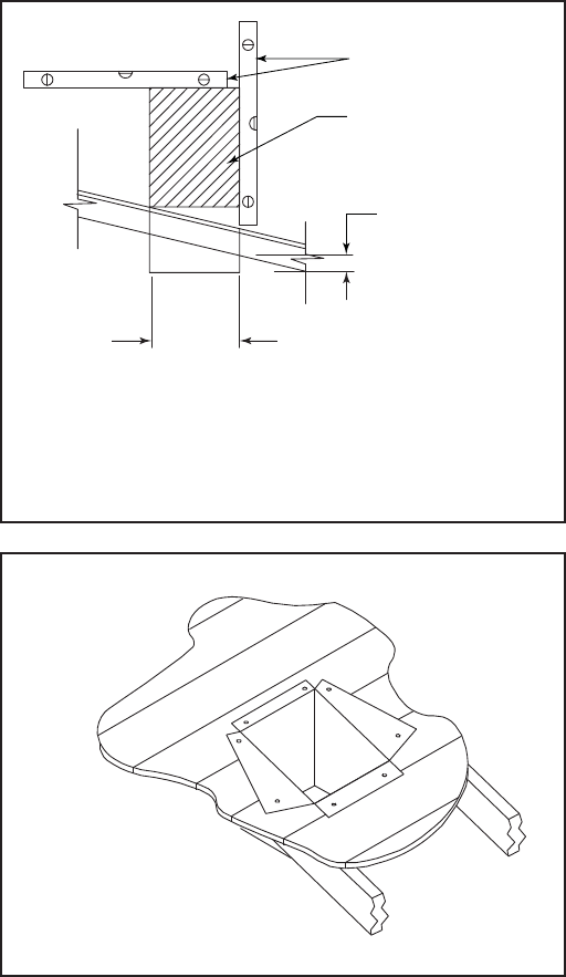
Heatilator • Novus NNXT • 4055-879 • Rev. o • 2/1244
Cut hole 1/8 in. (3 mm) greater
in size than pattern of support
box as it is projected onto
roofline.
2 in. (51 mm)
minimum below
finished ceiling
Cathedral ceiling
support box
Level
F. Install Decorative Ceiling Components
(SLP only)
A decorative ceiling thimble can be installed on a fl at ceil-
ing through which the vent passes. The decorative ceiling
thimble is used to cover the fi restop.
• Seal the gap between the vent pipe and fi restop using
silicone with a minimum of 300ºF continuous exposure
rating to prevent cold air infi ltration.
• Install the decorative ceiling thimble by sliding it up to
the ceiling and attaching it using the provided screws.
A decorative cathedral ceiling support box can be used
where vertical vent runs pass through a cathedral ceiling.
• Use a plumb-bob to mark the center line of the venting
system on the ceiling and drill a small hole through the
ceiling and roof at this point. Locate the hole and mark
the outline of the cathedral ceiling support box on the
outside roof.
• Remove shingles or other roof covering as necessary
to cut the rectangular hole for the support box. Cut the
hole 1/8 in. (3 mm) larger than the support box outline.
• Lower the support box through the hole in the roof until
its bottom is at least 2 in. (51 mm) below the ceiling
(Figure 10.12).
• Level the support box both vertically and horizontally
and temporarily tack it in place through the inside walls
into the roof sheathing.
• Use tin snips to cut the support box from the top corners
down to the roof line and fold the resulting fl aps to the
roof. See Figure 10.13.
• Nail the fl aps to the roof AFTER running a bead of non
hardening sealant between the fl aps and the roof.
WARNING! Risk of Fire! Clean out ALL materials from
inside the support box and complete the vertical vent run
and termination.
Figure 10.12
Figure 10.13
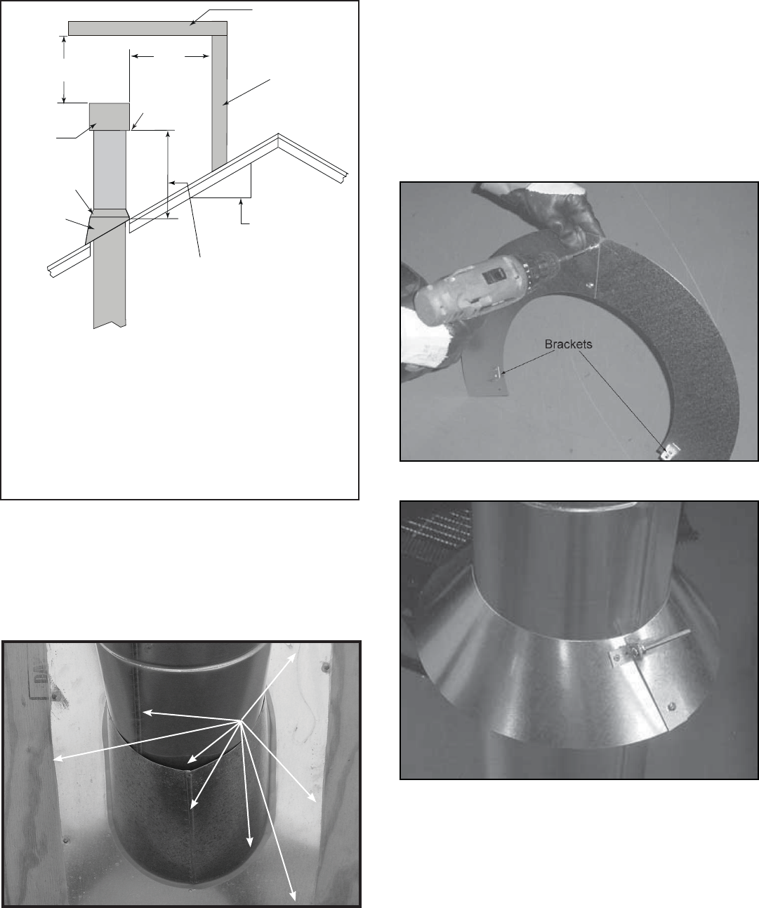
45Heatilator • Novus NNXT • 4055-879 • Rev. o • 2/12
G. Install Metal Roof Flashing
• See minimum vent heights for various pitched roofs
(Figure 10.14) to determine the length of pipe to extend
through the roof.
• Slide the roof fl ashing over the pipe sections extending
through the roof as shown in Figure 10.15.
Horizontal
overhang
12 X
20 in.
(508 mm)
Lowest
Discharge
Opening
Termination
Cap
Roof Pitch
is X / 12
Vertical
wall
H (min.) - Minimum height
from roof to lowest
discharge opening.
24 in. min.
(610 mm)
Roof Pitch H (Min.) Ft. Roof Pitch H (Min.) Ft.
Flat to 6/12 1.0* Over 11/12 to 12/12 4.0
Over 6/12 to 7/12 1.25* Over 12/12 to 14/12 5.0
Over 7/12 to 8/12 1.5* Over 14/12 to 16/12 6.0
Over 8/12 to 9/12 2.0* Over 16/12 to 18/12 7.0
Over 9/12 to 10/12 2.5 Over 18/12 to 20/12 7.5
Over 10/12 to 11/12 3.25 Over 20/12 to 21/12 8.0
* 3 ft. minimum in snow regions
Storm Collar
Roof
Flashing
Figure 10.14 Minimum Height From Roof To Lowest Discharge
Opening
Figure 10.15
H. Assemble and Install Storm Collar
CAUTION! Risk of Cuts, Abrasions or Flying Debris.
Wear protective gloves and safety glasses during installa-
tion. Sheet metal edges are sharp.
• Connect both halves of the storm collar with two screws
(see Figure 10.16).
• Wrap the storm collar around the exposed pipe section
closest to the roof and align brackets. Insert a bolt
(provided) through the brackets and tighten the nut to
complete the storm collar assembly (Figure 10.17). Make
sure the collar is tight against the pipe section.
• Slide the assembled storm collar down the pipe section
until it rests on the roof fl ashing.
• Caulk around the top of the storm collar (see Figure
10.24).
Figure 10.16 Assembling the Storm Collar
Figure 10.17 Assembling the Storm Collar Around the Pipe
CAULK
NOTICE: Failure to properly caulk the roof fl ashing and pipe
seams may permit entry of water.
• Caulk the gap between the roof fl ashing and the outside
diameter of the pipe.
• Caulk the perimeter of the fl ashing where it contacts the
roof surface. See Figure 10.15.
• Caulk the overlap seam of any exposed pipe sections that
are located above the roof line.
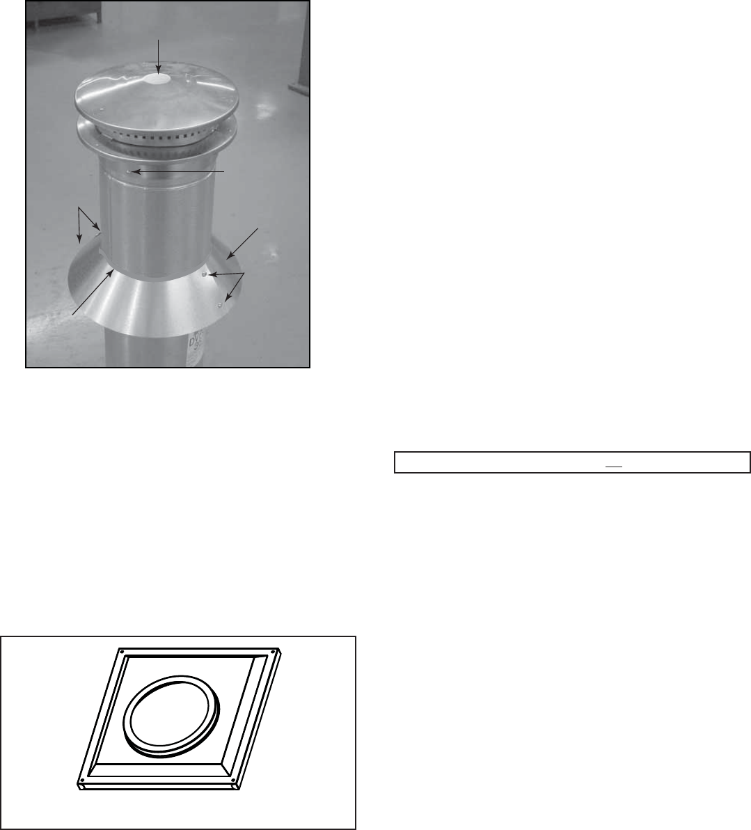
Heatilator • Novus NNXT • 4055-879 • Rev. o • 2/1246
J. Install Decorative Wall Components (SLP
only)
A decorative wall thimble can be installed on an interior
wall through which the vent passes. The decorative wall
thimble is used to cover the wall shield fi restop.
• Slide the decorative wall thimble over the last section of
horizontal pipe before passing through the wall to the
outside.
• Once the pipe section and the termination cap have
been connected, slide the wall thimble up to the interior
wall surface and attach with screws provided. See
Figure 10.19.
Important Notice: Heat shields may not be fi eld constructed.
K. Heat Shield Requirements for Horizontal
Termination
WARNING! Risk of Fire! To prevent overheating and fi re,
heat shields must extend through the entire wall thick-
ness.
• DO NOT remove the heat shields attached to the
wall shield fi restop and the horizontal termination
cap.
• Heat shields must overlap 1-1/2 in. (38 mm) mini-
mum.
There are two sections of the heat shield. One section
is factory-attached to the wall shield fi restop. The other
section is factory-attached to the cap. See Figure 10.20.
If the wall thickness does not allow the required 1-1/2 in.
(38 mm) heat shield overlap when installed, an extended
heat shield must be used.
• If the wall thickness is less than 4 in./102 mm (DVP) or
4-3/8 in./ 111 mm (SLP), the heat shields on the cap and
wall shield fi restop must be trimmed. A minimum 1-1/2
in. (38 mm) overlap MUST be maintained.
• Use an extended heat shield if the fi nished wall thickness
is greater than 7-1/4 in. (184 mm).
• The extended heat shield may need to be cut to length
maintaining suffi cient length for a 1-1/2 in. (38 mm)
overlap between heat shields.
• Attach the extended heat shield to either of the existing
heat shields using the screws supplied with the extended
heat shield. Refer to “Vent Components Diagrams” in
the back of this manual.
• Rest the small leg on the extended heat shield on top
of the pipe section to properly space it from the pipe
section.
Figure 10.19 Wall Thimble
I. Install Vertical Termination Cap
• Attach the vertical termination cap by sliding the inner
collar of the cap into the inner fl ue of the pipe section
while placing the outer collar of the cap over the outer
fl ue of the pipe section.
• Secure the cap by driving three self-tapping screws
(supplied) through the pilot holes in the outer collar of the
cap into the outer fl ue of the pipe (see Figure 10.18).
Figure 10.18
Storm
Collar
Termination Cap
(1 of three)
Caulk
Screws
Brackets/
Bolts
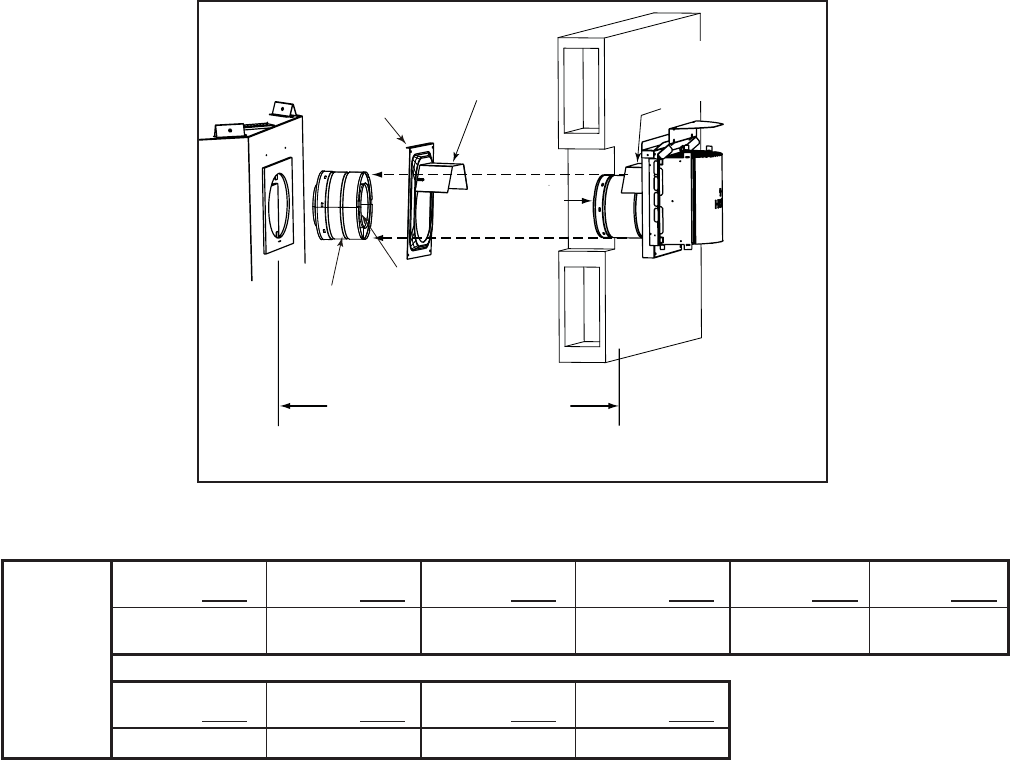
47Heatilator • Novus NNXT • 4055-879 • Rev. o • 2/12
INTERIOR
Heat Shield or
Extended
Heat Shield
Wall Shield
Firestop
Heat Shield
1-1/2 in. (38 mm) min.
overlap
SHEATHING
Vent depth from back of appliance to
outside surface of exterior wall
(see chart below)
Slip Section
can be extended
Inner Vent
Outer Vent
EXTERIOR
Figure 10.20 Venting through the wall
Note: When using termination caps with factory-supplied
heat shield attached, no additional wall shield fi restop is
required on the exterior side of a combustible wall.
L. Install Horizontal Termination Cap
WARNING! Risk of Fire! The telescoping fl ue section
of the termination cap MUST be used when connecting
vent.
• 1-1/2 (38 mm) minimum overlap of fl ue telescoping
section is required.
Failure to maintain overlap may cause overheating and
fi re.
• Vent termination must not be recessed in the wall. Siding
may be brought to the edge of the cap base.
• Flash and seal as appropriate for siding material at
outside edges of cap.
• When installing a horizontal termination cap, follow
the cap location guidelines as prescribed by current
ANSI Z223.1 and CAN/CGA-B149 installation codes
and refer to Section 6 of this manual.
CAUTION! Risk of Burns! Local codes may require
installation of a cap shield to prevent anything or anyone
from touching the hot cap.
NOTICE: For certain exposures which require superior
resistance to wind-driven rain penetration, a fl ashing kit and
HRC caps are available. When penetrating a brick wall, a
brick extension kit is available for framing the brick.
Cap Specifi cation Chart (depth without using additional pipe sections)
NNXT Series
DVP-TRAPK1
Top Vent Depth DVP-TRAP1
Rear Vent Depth DVP-TRAPK2
Top Vent Depth DVP-TRAP2
Rear Vent Depth SLP-TRAP1
Top Vent Depth SLP-TRAP2
Top Vent Depth
4 1/2 to 6 3/8 in. 3 to 4 7/8 in. 6 7/8 to 10 7/8 in. 5 3/8 to 9 3/8 in. 2 to 3 7/8 in. 4 3/8 to 8 3/8
in.
DVP-HPC1
Top Vent Depth DVP-HPC1
Rear Vent Depth DVP-HPC2
Top Vent Depth DVP-HPC2
Rear Vent Depth
4 1/2 to 6 5/8 in. 3 to 5 1/8 in. 6 5/8 to 10 3/4 in. 5 1/8 to 9 1/4 in.
DVP-TRAP1 can adjust 1 1/2 in. (3 1/8 to 4 5/8)
DVP-TRAP2 can adjust 4 in. (5 3/8 to 9 3/8)
SLP-TRAP1 can adjust 1 5/8 in. (3 1/8 to 4 3/4)
SLP-TRAP2 can adjust 4 in. (5 1/4 to 9 1/4))
DVP-HPC1 can adjust 2 1/8 in. (4 1/4 to 6 3/8)
DVP-HPC2 can adjust 4 1/8 in. (6 3/8 to 10 1/2)
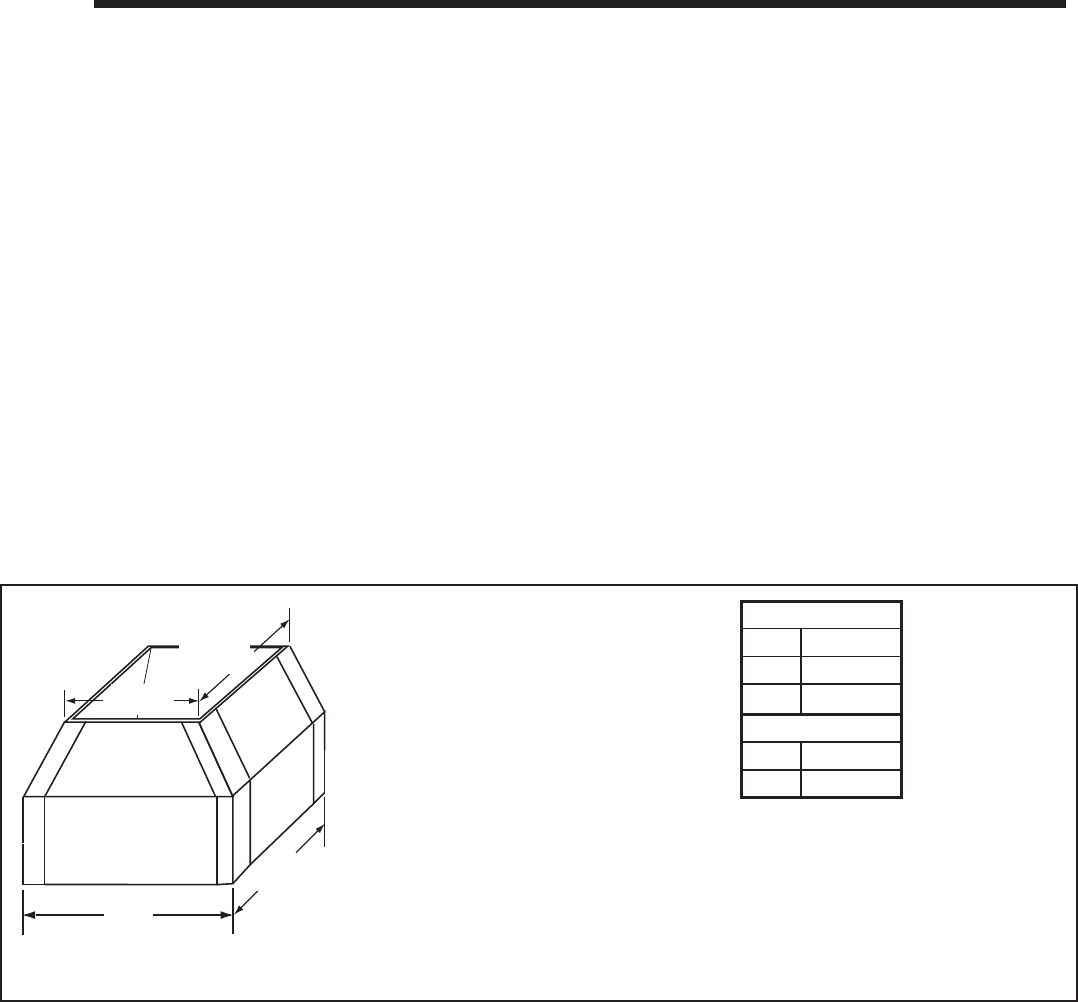
Heatilator • Novus NNXT • 4055-879 • Rev. o • 2/1248
11
11 Shrouds
• Chase top shrouds may be fi eld constructed where permitted by regional building codes.
WARNING! Risk of Fire! Shrouds must be constructed
as specifi ed. Improper construction may overheat chase
top.
NOTICE: Some regional codes require an agency-Listed
shroud. Consult your local building offi cials.
• The following fi eld constructed shroud designs have been tested for Hearth Technologies fi replace systems and termination
caps.
• The shrouds must be constructed from a minimum .018 in. (26 ga) thick aluminized steel.
• The wire mesh is optional but recommended and must be .018 in. thick minimum, 1/2 in. mesh.
A. HHT Shrouds
• You may install a shroud with this fi replace. See Section 17.D. for a list of UL Listed shrouds. Follow the instructions
included with these optional components
Min.
Base Dim.
Min.
Base Dim.
Min.
Top Dim.
Min.
Top Dim.
Figure 11.1 Open Top Shroud Dimensions
B. Field Constructed Shrouds
Open Top Shroud (may be used with DVP-TV, DVP-TVHW, SLP-TVHW)
Min. Base Dims.
in 19 x 19
mm 483 x 483
Min. Top Dims.
in 16 x 16
mm 406 x 406
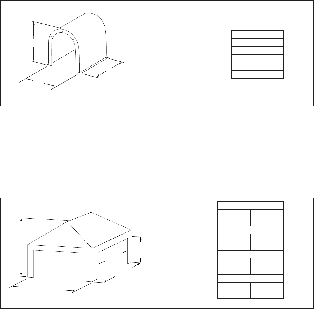
49Heatilator • Novus NNXT • 4055-879 • Rev. o • 2/12
Min. Base Dim
Min. Height
Min.
Base Dim
Figure 11.2 Mailbox Style Shroud Dimensions
Minimum
Opening
Height
Minimum
Base Dimension
Min. Opening
Width
Min. Base Dimension
Minimum
Height
Figure 11.2 Roofed Style Shroud Dimensions
Roofed Style Shroud (may be used with DVP-TV, DVP-TVHW, SLP-TVHW)
Mailbox Style Shroud (may be used with DVP-TV, DVP-TVHW, SLP-TVHW)
Min. Base Dims.
in 20 x 20
mm 508 x 508
Min. Height
in 18
mm 457
Min. Base Dims.
in 20 x 20
mm 508 x 508
Min. Height
in 18
mm 458
Min. Opening Width
in 14
mm 356
Min. Opening Height
in 10
mm 254
Heatilator • Novus NNXT • 4055-879 • Rev. o • 2/1250
A. Fuel Conversion
• Make sure the appliance is compatible with available
gas types.
• Conversions must be made by a qualified service
technician using Hearth & Home Technologies specifi ed
and approved parts.
B. Gas Pressure
• Optimum appliance performance requires proper input
pressures.
• Gas line sizing requirements will be determined in ANSI
Z221.3 National Fuel Gas Code in the USA and CAN/
CGA B149 in Canada.
• Pressure requirements are:
C. Gas Connection
• Refer to Reference Section 17.A. for location of gas line
access in appliance.
• Gas line may be run through knockout(s) provided.
• The gap between supply piping and gas access hole
may be caulked with caulk with a minimum of 300ºF
continuous exposure rating, or stuffed with non-
combustible, unfaced insulation to prevent cold air
infi ltration.
• Ensure that gas line does not come in contact with outer
wrap of the appliance. Follow local codes.
• Pipe incoming gas line into valve compartment.
• Connect incoming gas line to the 1/2 in. (13 mm)
connection on manual shutoff valve.
WARNING! Risk of Fire or Explosion! Support control
when attaching pipe to prevent bending gas line.
• A small amount of air will be in the gas supply lines.
WARNING! Risk of Fire or Explosion! Gas build-up dur-
ing line purge could ignite.
• Purge should be performed by qualified service
technician.
• Ensure adequate ventilation.
• Ensure there are no ignition sources such as sparks or
WARNING! Risk of Fire or Explosion! High pressure
will damage valve. Low pressure may cause explosion.
• Verify inlet pressures. Verify minimum pressures when
other household gas appliances are operating.
• Install regulator upstream of valve if line pressure is
greater than 1/2 psig.
12
12 Gas Information
Gas Pressure Natural Gas Propane
Minimum inlet pressure 5.0 in. w.c. 11.0 in. w.c.
Maximum inlet pressure 10.0 in. w.c. 13.0 in. w.c.
Manifold pressure 3.5 in. w.c. 10.0 in. w.c.
Note: Have the gas supply line installed in accordance with
local codes, if any. If not, follow ANSI 223.1. Installation
should be done by a qualifi ed installer approved and/or
licensed as required by the locality. (In the Commonwealth
of Massachusetts installation must be performed by a
licensed plumber or gas fi tter).
Note: A listed (and Commonwealth of Massachusetts
approved) 1/2 in. (13 mm) T-handle manual shut-off valve
and fl exible gas connector are connected to the 1/2 in. (13
mm) control valve inlet.
• If substituting for these components, please consult
local codes for compliance.
D. High Altitude Installations
NOTICE: If the heating value of the gas has been reduced,
these rules do not apply. Check with your local gas utility or
authorities having jurisdiction.
When installing above 2000 feet elevation:
• In the USA: Reduce burner orifi ce 4% for each 1000 feet
above 2000 feet.
• In CANADA: Reduce burner orifi ce 10% for elevations
between 2000 feet and 4500 feet. Above 4500 feet,
consult local gas utility.
Fire Risk.
Explosion Hazard.
High pressure will damage valve.
• Disconnect gas supply piping BEFORE
pressure testing gas line at test pressures
above 1/2 psig.
• Close the manual shutoff valve BEFORE
pressure testing gas line at test pressures
equal to or less than 1/2 psig.
WARNING
open fl ames.
Light the appliance. It will take a short time for air to purge
from lines. When purging is complete the appliance will
light and operate normally.
WARNING! Risk of Fire, Explosion or Asphyxiation!
Check all fi ttings and connections with a non-corrosive
commercially available leak-check solution. DO NOT use
open fl ame. Fittings and connections could have loos-
ened during shipping and handling.
WARNING! Risk of Fire! DO NOT change valve settings.
This valve has been preset at the factory.

51Heatilator • Novus NNXT • 4055-879 • Rev. o • 2/12
A. Wiring Requirements
NOTICE: This appliance must be electrically wired
and grounded in accordance with local codes or, in the
absence of local codes, with National Electric Code
ANSI/NFPA 70-latest edition or the Canadian Electric
Code CSA C22.1.
• Wire the appliance junction box to 120 VAC. This is
required for use of optional accessories (standing pilot
ignition) or proper operation of the appliance (Intellifi re
Plus™ ignition).
• A 120 VAC circuit for this product must be protected with
ground-fault circuit-interrupter protection, in compliance
with the applicable electrical codes, when it is installed
in locations such as in bathrooms or near sinks.
• Low voltage and 120 VAC voltage cannot be shared
within the same wall box.
WARNING! Risk of Shock or Explosion! DO NOT wire
120V to the valve or to the appliance wall switch. Incorrect
wiring will damage controls.
B. Intellifi re Plus™ Ignition System Wiring
• Wire the appliance junction box to 120 VAC for proper
operation of the appliance.
WARNING! Risk of Shock or Explosion! DO NOT wire
IPI controlled appliance junction box to a switched circuit.
Incorrect wiring will override IPI safety lockout.
• Refer to Figure 13.1, Intellifi re Plus intermittent pilot
ignition (IPI) wiring diagram.
• This appliance is equipped with an Intellifi re control valve
which operates on a 6-volt system.
• Plug the 6-volt DC power supply into the appliance
junction box to supply power to the unit
• For battery backup protection, install four AA-cell
batteries (not included) into the battery pack before use.
Remove batteries if the fi replace will not be used for an
extended period of time.
NOTICE: Battery polarity must be correct or module damage
will occur.
C. Optional Accessories Requirements
• This appliance may be used with a wall switch, wall
mounted thermostat and/or a remote control.
• Wiring for optional Hearth & Home Technologies
approved accessories should be done now to avoid
reconstruction. Follow instructions that come with those
accessories.
• Hearth & Home Technologies recommends that Intelli-
Fire PlusTM wireless controls be used for their features
and functionality with the IntelliFire PlusTM ignition sys-
tem.
• A standard ON/OFF switch is compatible.
13
13 Electrical Information
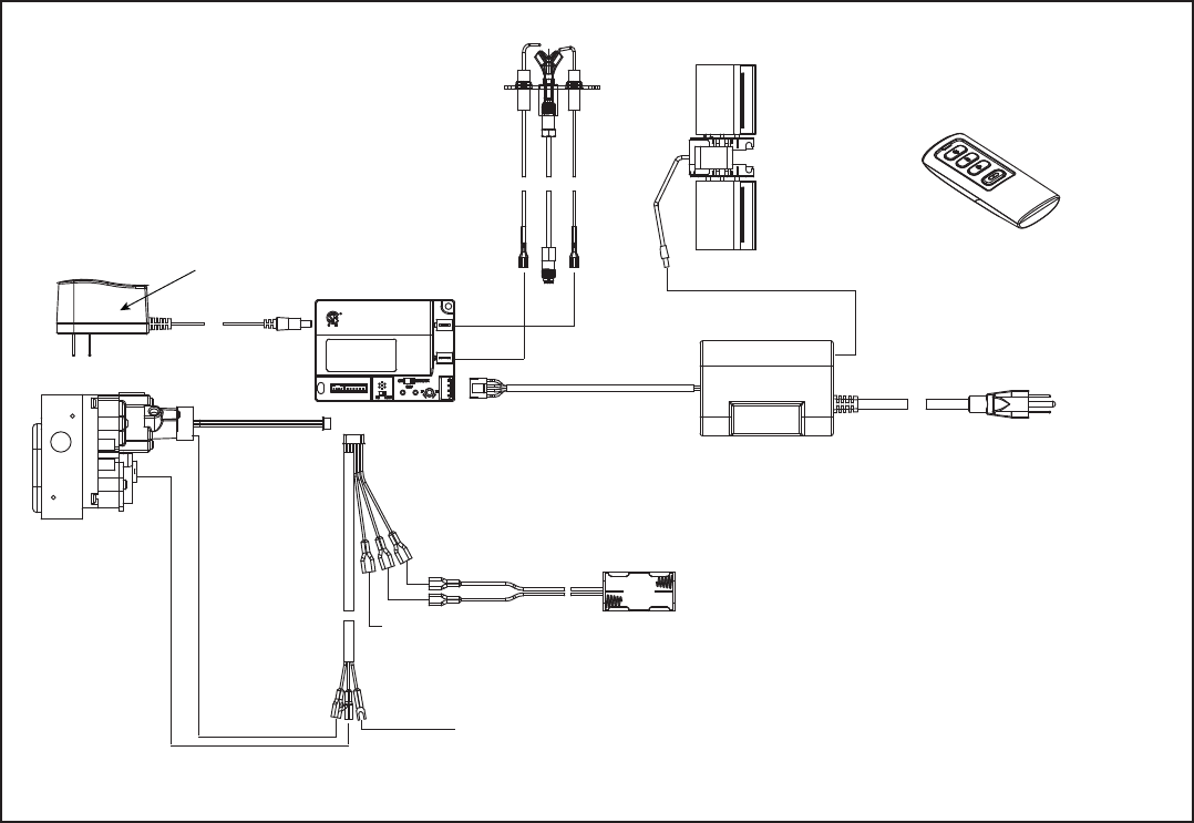
Heatilator • Novus NNXT • 4055-879 • Rev. o • 2/1252
D. Electrical Service and Repair
WARNING! Risk of Shock! Label all wires prior to
disconnection when servicing controls. Wiring errors can
cause improper and dangerous operation. Verify proper
operation after servicing.
TO JUNCTION
BOX (120V)
CONTROL MODULE
I
S
FLAME
SENSE
WHITE
WHITE
ORANGE
IGNITER
3 PRONG 120VAC
RC200 12V DC
(A23 X 1)
TO JUNCTION
BOX 120VAC
GROUND
ORANGE
(PILOT) GREEN
(MAIN) BROWN
BLACK
RED
BROWN/RED
OPTIONAL ON/OFF
SWITCH
BATTERY PACK
6V DC
FLAME
MODULATION
AUX200 MODULE
FAN
6V DC
SUPPLY
Figure 13.1 RC200 Wiring Diagram
WARNING! Risk of Shock! Replace damaged wire with
type 105° C rated wire. Wire must have high temperature
insulation.
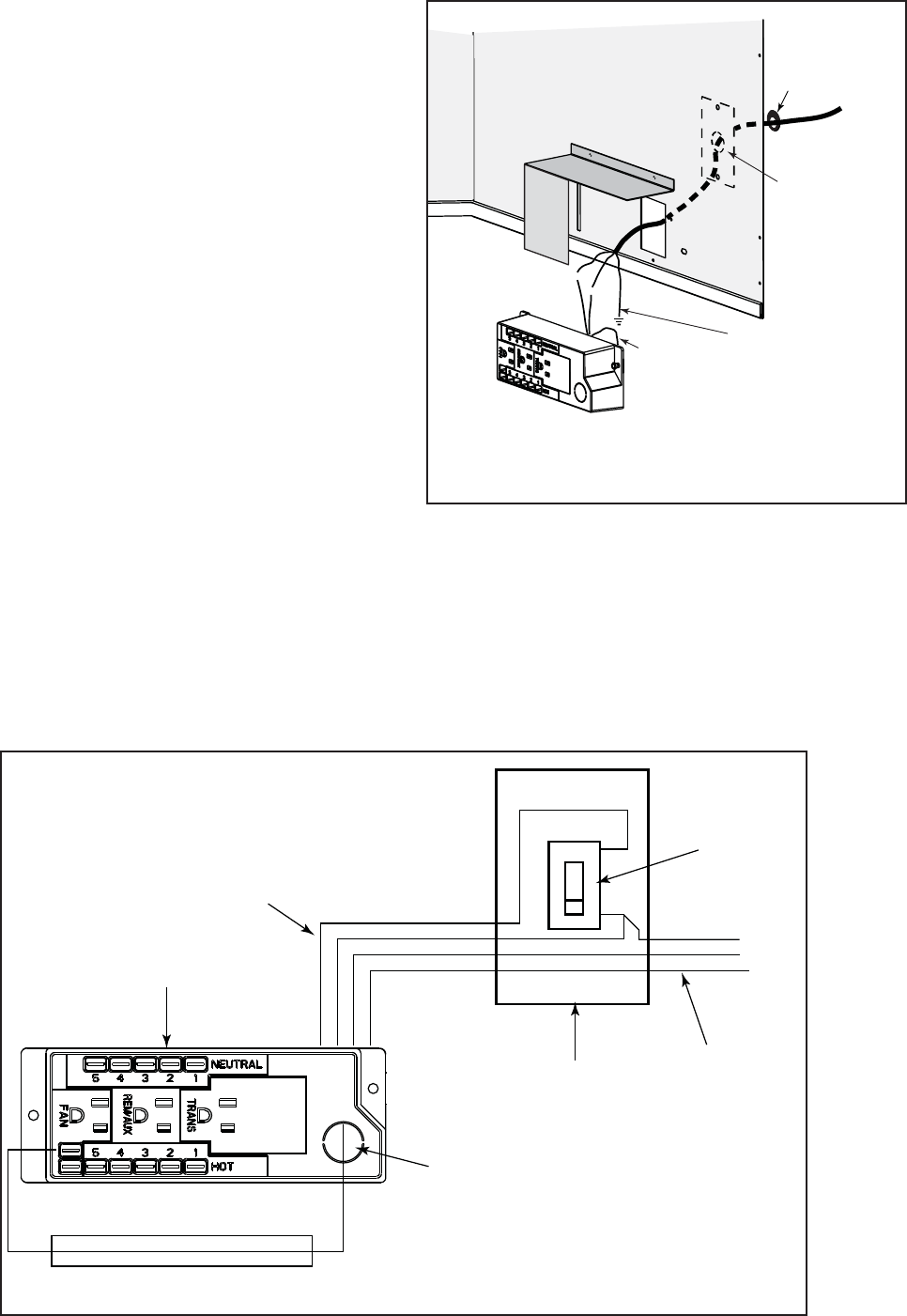
53Heatilator • Novus NNXT • 4055-879 • Rev. o • 2/12
F. Wall Switch Installation for Fan (Optional)
If the box is being wired to a wall mounted switch for use with a fan, see Figure 13.3:
• The power supply for the appliance must be brought into a switch box.
• The power can then be supplied from the switch box to the appliance using a minimum of 14-3 with ground wire.
• At the switch box connect the black (hot) wire and red (switch leg) wire to the wall switch as shown.
• At the appliance connect the black (hot), white (neutral) and green (ground) wires to the junction box as shown.
• Add a 1/4 in. insulated female connector to the red (switch leg) wire, route it through the knockout in the face of the
junction box, and connect to the top fan switch connector (1/4 in. male) as shown.
WHT
WHT
BLK
BLK
GRN wire
inside box
Copper
ground attached
to GRN screw with
GRN wire
14/2WG
Cover Plate
outside firebox
Romex
Connector
Figure 13.2 Junction Box Detail
Red
Switch
Switch Box
Red
Black
Black
Green Green
White
Power
Supply
Wires
White
Red
Black
Green
White
Minimum 14-3 AWG
with Ground
Junction Box
Knockout
Figure 13.3 Junction Box Wired to Wall Switch or BC10
E. Junction Box Installation
If the box is being wired from the INSIDE of the appli-
ance:
• Remove the screw attaching the junction box/receptacle
to the outer shell, rotate the junction box inward to
disengage it from the outer shell (see Figure 13.2).
• Pull the electrical wires from outside the appliance
through this opening into the valve compartment. See
Figure 13.4.
If the box is being wired from the OUTSIDE of the appli-
ance:
• Remove the cover plate located on the outer shell - right
side (see Figure 13.2).
• Install the supplied Romex™ connector in the cover
plate.
• Make all necessary wire connections and reattach the
cover plate to the outer shell.

Heatilator • Novus NNXT • 4055-879 • Rev. o • 2/1254
Installation & Operating Instructions
RC200
IntelliFire Plus™ Multifunction Remote Control
Hearth & Home Technologies disclaims any responsibility for,
and the warranty will be voided by, the following actions:
• Installation and use of any damaged system component.
• Modifi cation of the system component.
• Installation other than as instructed by Hearth & Home
Technologies.
• Installation and/or use of any component part not approved
by Hearth & Home Technologies.
Any such action may cause a fi re hazard.
• Read, understand and follow these instructions for safe
installation and operation.
Introduction
The RC200 multifunctional wireless control with dock-
ing station is designed to control constant pilot feature,
fl ame height, blower speed and to turn your gas fi re-
place on and off. The RC200 remote control is only for
use with the Hearth & Home Technologies IntelliFire
Plus™ system (IPI).
FCC Requirements
WARNING! Risk of Fire! Changes or modifi cations to
this unit not expressly approved by the party responsible
for compliance could void the user’s authority to operate
the equipment.
Note: This equipment has been tested and found to
comply with the limits for a Class B digital device, pur-
suant to Part 15 of the FCC Rules. These limits are
designed to provide reasonable protection against
harmful interference in a residential installation. This
equipment generates, uses, and can radiate radio
frequency energy and, if not installed and used in ac-
cordance with the instructions, may cause harmful in-
terference to radio communications. However, there is
no guarantee that interference will not occur in a partic-
ular installation. If this equipment does cause harmful
interference to radio or television reception, which can
be determined by turning the equipment off and on, the
user is encouraged to try to correct the interference by
one or more of the following measures:
• Reorient or relocate the receiving antenna.
• Increase the separation between the equipment and
receiver.
• Connect the equipment into an outlet on a circuit dif-
ferent from that to which the receiver is connected.
• Contact the dealer or an experienced radio TV techni-
cian for help.
Canadian Equipment Requirements
This digital apparatus does not exceed the (Class A/ Class
B) limits for radio noise emissions from digital apparatus
set out in the Radio Interference Regulations of the Cana-
dian Department of Communications. Le present appareil
numerique n’emet pas de bruits radioelectriques depas-
sant les limites applicables aux appareils numeriques (de
la class A/de la class B) prescrites dans le Reglement sur
le brouillage radioelectrique edicte par le ministere des
Communications du Canada.
This device complies with RSS-210 of Industry and Science
Canada. Operation is subject to the following two condi-
tions: (1) this device may not cause interference, and (2)
this device must accept any interference, including interfer-
ence that may cause undesired operation of the device.
Installation Precautions
This control is tested and safe when installed in accor-
dance with this installation manual. Do not install any
components that may be damaged.
Do not modify, disassemble, or substitute any of the com-
ponents included with this kit. Installation of this unit must
be done by a qualifi ed service technician.
Placement of this remote control may affect performance.
An assessment of the space should be done prior to in-
stallation for optimum performance.
Determine Location
Determine the location for the remote control. The selected
location should be in the same space as the gas fi replace
with visual sight of fi replace. The remote control must be
placed within 30 feet of the fi replace but should not be
exposed to extreme heat.
The RC200 is approved for interior installation and should
always be placed under weather resistant cover when used
in exterior applications.
• Keep remote control out of reach of children.
G. Remote Control Installation & Operations
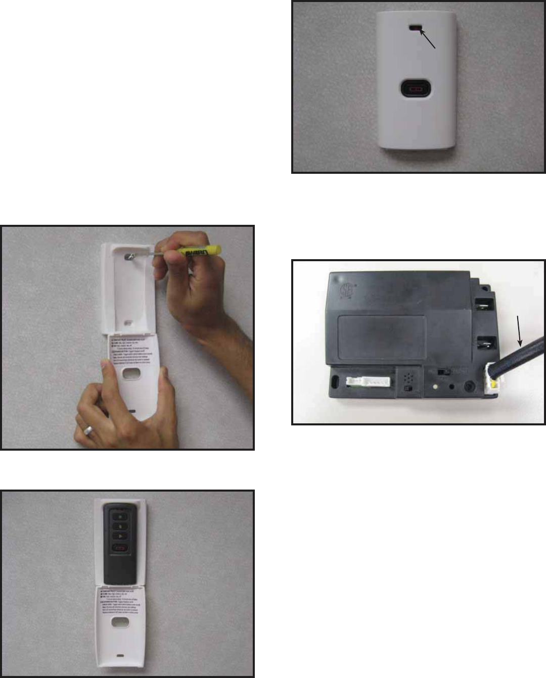
55Heatilator • Novus NNXT • 4055-879 • Rev. o • 2/12
Figure 3. Mounting Remote Control Housing
5. Close the housing door and press the power button.
The red light illuminates if the battery was properly in-
stalled. See Figure 3.
Fan Installation
• Insert the 3 prong plug from the fan into the receptacle
located in the AUX200 module. See Figure 5.
Figure 4. AUX 200 module installation
RED LED
RED LED
AUX200
AUX200
CABLE
CABLE
AUX200 Module Installation
• Control Module should be set in the OFF position before
any components are installed.
• Insert the 4 hole harness from the AUX200 module into
the 4 pin plug on the control module. See Figure 4.
Figure 2. Remote in Housing
Installation of Remote Control Housing
CAUTION! Risk of Fire! DO NOT install damaged or
modifi ed components.Warranty will be voided if damaged
or modifi ed components are installed.
Kit components: One remote control, two #6 screws, two
wall anchors, one A23 battery and one AUX200 module (if
purchased retail).
1. Remove remote control components from packaging.
2. Remove battery cover from the back of the remote by
sliding it down and install A23 battery.
To prevent unintended operation when not using your fi re-
place for an extended period of time (summer months,
vacation, trips, etc):
• Remove battery from remote control.
• Unplug switching adapter and remove back-up batteries.
3. Secure the remote control housing on a fl at wall sur-
face using the two screws and wall anchors provided.
See Figure 1.
Figure 1. Mounting Remote Control Housing
4. Place remote control inside housing. See Figure 2.
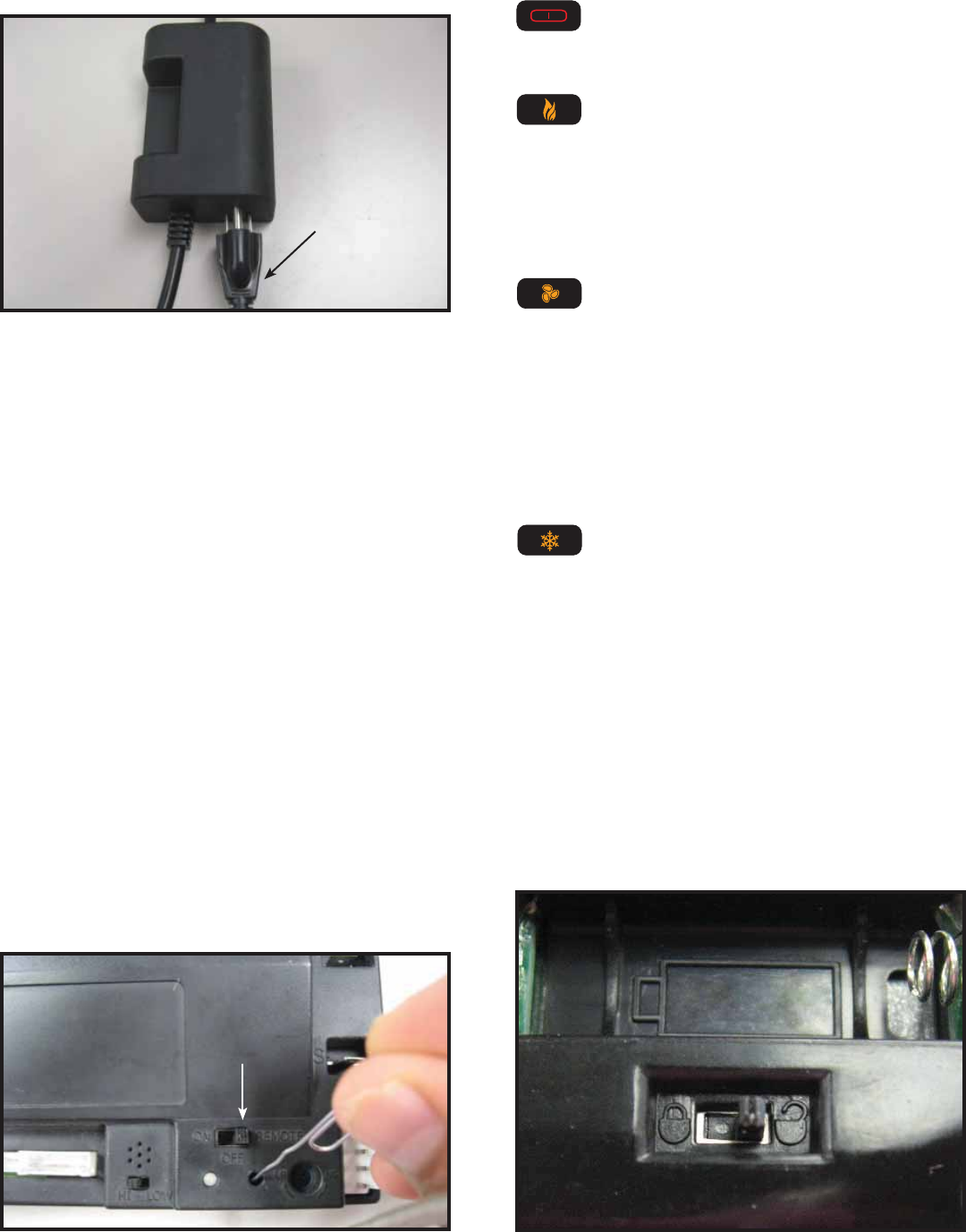
Heatilator • Novus NNXT • 4055-879 • Rev. o • 2/1256
Figure 6. Programming RC200
REMOTE POSITION
REMOTE POSITION
Figure 5. Plug Fan into AUX200 Module
Programming the RC200 to the Control Module
CAUTION! Risk of burns! DO NOT program the remote
control to the control module when fi replace is hot.
• Verify the ON/OFF/REMOTE switch is in the REMOTE
position. Green LED light will blink three times and beep
once 5 seconds later when ready. See Figure 6.
• Using a small item (such as a paper clip) press and
release the learn button located near the ON/OFF/
REMOTE switch. See Figure 6.
• Control module will beep once and LED will blink green
for 10 seconds.
• While the LED is blinking, press the power button on
the remote control. A double beep will come out of the
control module to indicate that it has been programmed
successfully.
NOTICE: Up to three remote controls can be programmed
into the control module. Simply press a button on the other
remote controls during the 10 second programming process
to add another remote into the system.
To clear memory in the control module, use a small item
(such as a paper clip) to press and release the LEARN
button. Control module will beep once and LED will blink
green for 10 seconds DO NOT press any buttons on the
remote during the ten seconds that the green LED blinks.
The memory will be cleared.
FAN CORD
FAN CORD
• Insert 3 prong plug from AUX200 module into REM/AUX
receptacle of fi replace junction box.
Press the PILOT button to activate or deactivate
the constant pilot. The control module will beep
once indicating constant pilot has been activat-
ed. A double beep indicates the constant pilot
has been deactivated.
Press the FLAME button to adjust the fl ame
height. The fl ame height can be adjusted to 5
different settings: MAX, HIGH, MEDIUM, LOW,
MIN. Flame height will not be adjustable for fi rst
ten seconds when fi replace is turned on. The
system remembers the previous fl ame height
setting and will automatically adjust to previ-
ous setting after 10 seconds.
Press the FAN button to adjust the fan speed.
The FAN speed can be adjusted to 4 different
settings: HIGH, MED, LOW and OFF. The fan
has a timer built into the control module. After
the fi replace is turned ON the timer will wait for
7 minutes before turning on the fan. In addition,
the fan will remain on for 12 minutes after the
fi replace has been turned OFF. Whenever the
fan is turned ON, the FAN will start up on the
high setting for 10 seconds before adjusting to
the previous user setting.
Function Buttons
Press the POWER button to turn the fi replace
ON and OFF. The fi replace will fi rst ignite the pi-
lot. Once the pilot fl ame is established the main
burner will be lit.
Setting the Child Lock
• Remove battery cover from the back of the remote by
sliding it down. Slide the child lock switch to enable or
disable the child lock feature. See Figure 7.
NOTICE: No functions will be usable until child lock feature
is disabled.
Figure 7. Child Lock Switch
NOTICE: Whenever the fi replace is cycled from OFF to
ON, the main burner will light on high for 10 seconds before
returning to the previous user setting.

57Heatilator • Novus NNXT • 4055-879 • Rev. o • 2/12
Frequently Asked Questions/Troubleshooting
Please contact your Hearth & Home Technologies
dealer with any questions or concerns.
For the location of your nearest
Hearth & Home Technologies dealer,
please visit www.fi reside.com.
Symptom Possible Cause Corrective Action
Remote control will not transmit
Batteries Verify battery is functional and installed correctly.
Remote control is in Child
Lock mode Disengage Child Lock mode.
Control module will not take
commands from remote control
Control module is not in
“REMOTE” mode Ensure module switch is set to REMOTE.
Control module and remote
control are not programmed
to each other
The control module will beep when it successfully receives a
command. If it does not beep, clear module memory and re-
program wall switch.
Control module is
unplugged. In case of
power outage, backup
batteries are depleted or
missing
If red LED light comes on when power button is pressed, verify
that the control module is plugged in the fi replace junction box
located in the controls area. Also verify that the batteries are
installed in the battery pack.
Fan does not turn on when fi replace
is started Built in time delay The fi replace must run for seven minutes in order for the fan
to engage.
Fan does not turn off when fi replace
turned off Built in time delay The fan will run for twelve minutes after the fi replace is turned off.
Fireplace shuts down after extended
periods Built-in timer The fi replace will automatically shut down after nine hours of
continuous operation if it does not receive a command from
the remote.
Fireplace is on but will not shut off
with the remote control
External wired wall switch The fi replace cannot be turned off by remote if an external
wired wall switch is installed and in the ON position. Turn ex-
ternal wall switch to OFF.
Remote control or control
module failure
At control module, turn off fi replace by sliding the ON/OFF/RE-
MOTE switch to OFF. Warning! Risk of Fire! Fireplace is hot.
Use caution when accessing module.
Power Outage
• If fi replace battery backup system IS installed at time of
power outage, fi replace operation will not be interrupted.
• If fi replace battery backup system IS NOT installed at
time of power outage, fi replace will shut off. To resume
fi replace operation, install battery backup.
NOTICE: Battery polarity must be correct or module
damage will occur.
Manual Fireplace Shutoff
In the unlikely event that the remote wall switch malfunc-
tions and will not turn off the fi replace, call your dealer
for service assistance. In the meantime, you may choose
one of the following actions to turn off the fi replace:
CAUTION! Risk of burns! Fireplace surfaces are hot
when operating and during cool down. Use care and wear
gloves when opening the front and accessing compo-
nents inside the fi replace.
The fi replace may be manually shut down by one of the
following methods:
Turn off the control module:
• Open or remove the decorative front to access the control
module.
• Move switch to OFF (See Figure 6).
Disconnect power to the control module:
• Open or remove the decorative front to access power
cord to the junction box and/or back-up batteries.
• Unplug the control module and/or remove back-up
batteries.
Shut off gas to the control:
• Open or remove the decorative front and locate the gas
shut-off valve to the left of the gas control.
• Rotate the valve 90 degrees to turn off gas supply.
Turn off power to the fi replace (if back-up batteries are
not installed):
• Locate house circuit breaker for fi replace.
• Turn off the circuit breaker.
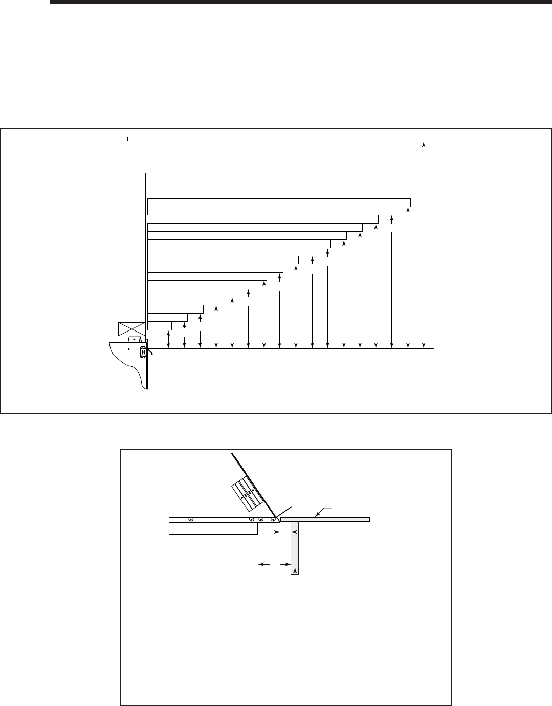
Heatilator • Novus NNXT • 4055-879 • Rev. o • 2/1258
1 in. (25 mm) min.
to perpendicular wall
A
3-1/2 in. (89 mm) min.
from fireplace opening
to perpendicular wall
B
Mantel Leg or
Perpendicular Wall
Top of
Appliance
Drywall
A
B
Measured from top of hood (in inches)
3 4 5 6 7 8 9 10 11 12 13 14 15 16 17
18
5 5-1/2
6-1/4 7 7-3/4
8-1/2
9-1/4 10 10-3/4
11-1/2
12-1/4 13 13-3/4
14-1/2
15-1/4 16
30 in. minimum
to ceiling
14
14 Finishing
A. Mantel and Wall Projections
WARNING! Risk of Fire! Comply with all minimum clear-
ances to combustibles as specifi ed. Framing or fi nishing
material closer than the minimums listed must be construct-
ed entirely of non-combustible materials (i.e., steel studs,
concrete board, etc).
Figure 14.1 Minimum Vertical and Maximum Horizontal Dimensions
Note: All
measurements
in inches.
Figure 14.2 Mantel Leg or Wall Projections (Acceptable on both sides of opening)
Mantels
Mantel Legs or Wall Projections
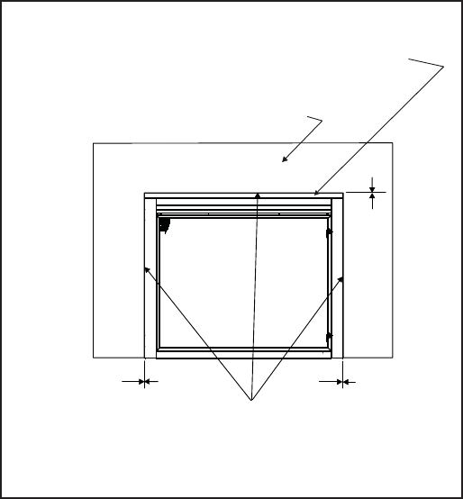
59Heatilator • Novus NNXT • 4055-879 • Rev. o • 2/12
0 in. 0 in.
High Temperature Sealant (300° F/149° C min.)
Top and Side Seal Joint
0 in.
Finish wall material may be
combustible on sides and up to
non-combustible strip on top.
Non-combustible strip shipped with appliance.
DO NOT REMOVE!
May be covered with non-combustible materials only.
B. Facing Material
• Metal front faces may be covered with non-combustible
materials only.
• Facing and/or fi nishing materials must not interfere with
air fl ow through louvers, operation of louvers or doors,
or access for service.
• Facing and/or fi nishing materials must never overhang
into the glass opening.
• Observe all clearances when applying combustible
materials.
• Seal joints between the fi nished wall and appliance top
and sides using a 300°F minimum sealant. Refer to
Figure 14.3.
WARNING! Risk of Fire! DO NOT apply combustible ma-
terials beyond the minimum clearances. Comply with all
minimum clearances to combustibles as specifi ed in this
manual. Overlapping materials could ignite and will inter-
fere with proper operation of doors and louvers.
Figure 14.3 Non-combustible Facing Diagram
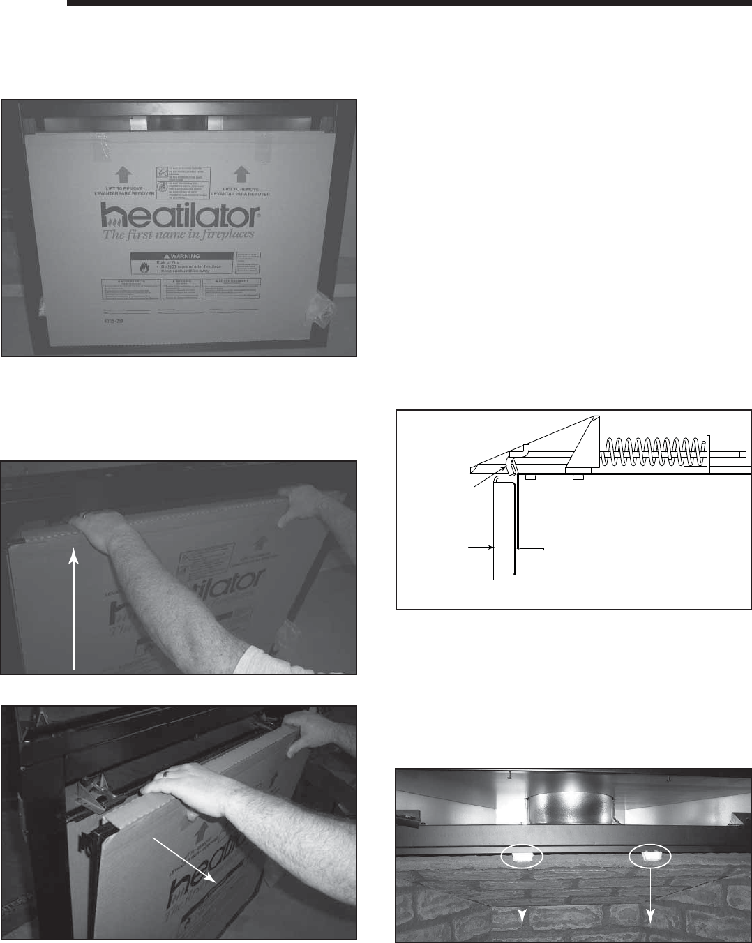
Heatilator • Novus NNXT • 4055-879 • Rev. o • 2/1260
15
15 Appliance Setup
A. Remove the Packaging
Remove the shrink fi lm, corrugated top cap, bottom cap
and column protectors from the appliance. The appliance
should look as shown in Figure 15.1.
B. Remove Screen Package Assembly
• Grasp the top of the screen package and lift up to
remove. See Figures 15.2 and 15.3.
Figure 15.1 Appliance Unwrapped
Figure 15.2 Lift up on Screen Package
Figure 15.3 Remove Screen Package
C. Remove the Shipping Materials
Remove the shipping materials from inside or underneath
the fi rebox.
Latches
(both bottom
and top)
Glass
Assembly
Figure 15.4 Glass Assembly
D. Removing Fixed Glass Assembly
WARNING! Risk of Asphyxiation! Handle fi xed glass
assembly with care. Inspect the gasket to ensure it is
undamaged and inspect the glass for cracks, chips or
scratches.
DO NOT:
• Strike, slam or scratch glass
• Operate fi replace with glass removed, cracked,
broken or scratched.
Replace fi xed glass assembly as a complete assembly.
• Remove screen.
• Pull the four (30/33/36 in. appliances) or seven (42 in.
appliance) glass assembly latches out of the groove on
the glass frame. Refer to Figure 15.4.
• Remove the glass assembly from the appliance.
E. Remove Top Log Pack
The top log pack is shipped inside the fi rebox. When you
remove the glass, the log pack will come out also.
F. Remove Packing Material
• Remove packing material (Figure 15.5).
Figure 15.5 Remove Lytherm Pieces
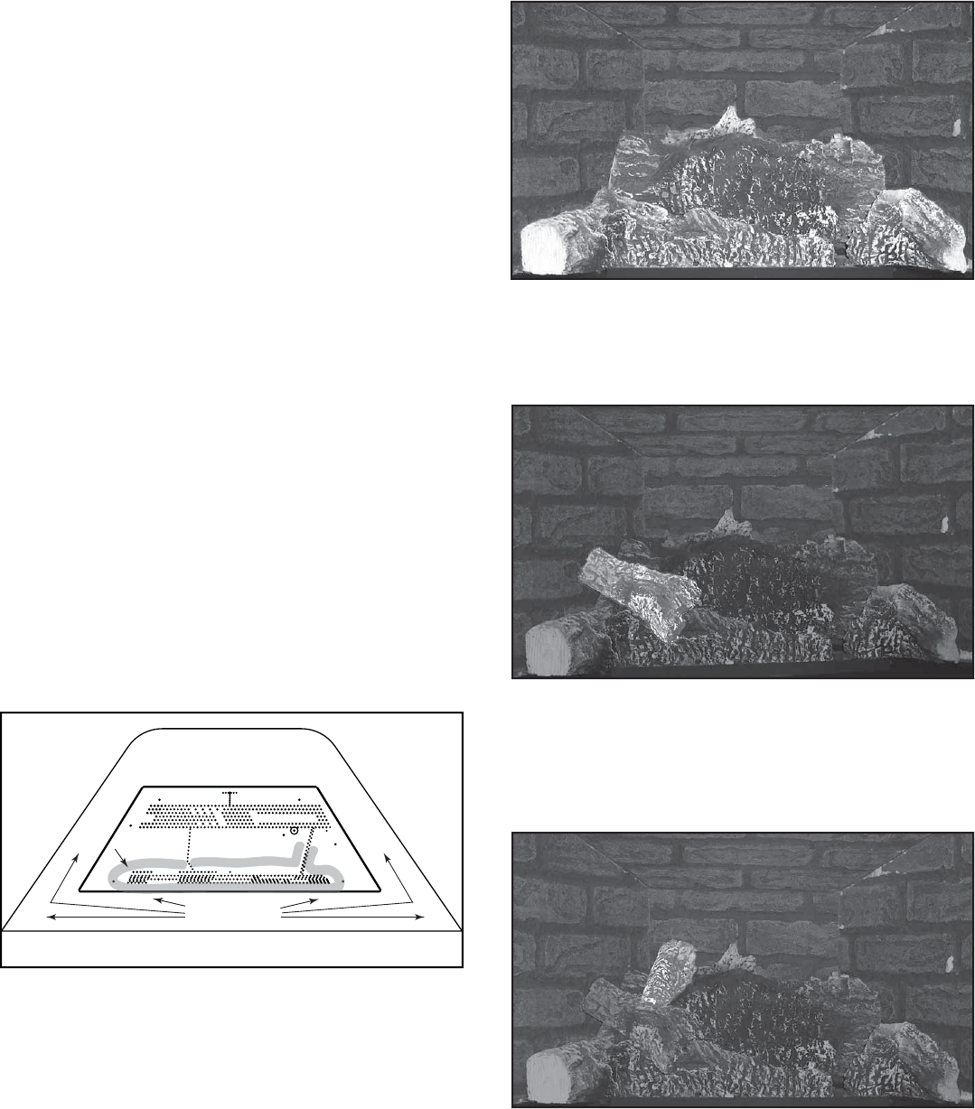
61Heatilator • Novus NNXT • 4055-879 • Rev. o • 2/12
G. Clean the Appliance
Clean/vacuum any sawdust that may have accumulated
inside the fi rebox or underneath in the control cavity.
H. Accessories
Install approved accessories per instructions included
with the accessories. Refer to Section 17.
WARNING! Rick of Fire and Electric Shock! Use ONLY
Hearth & Home Technologies-approved optional acces-
sories with this appliance. Using non-listed accessories
could result in a safety hazad and will void the warranty.
I. Place the Rockwool
WARNING! Risk of Explosion! Follow rockwool place-
ment instructions. DO NOT place rockwool directly over
burner ports. Replace rockwool material annually. Improp-
erly placed rockwool interferes with proper burner opera-
tion.
• Rockwool is shipped with this gas appliance.
• Place a small amount of 1/2 in. diameter pieces (dime-
size) rockwool on the burner pan so that the rockwool
touches, but does not cover, the holes in the burner
pan (refer to Figure 15.5). This will provide the “glowing
embers” look.
• It is not necessary to use the entire bag. Save the
remaining rockwool for future use.
K. Place the Vermiculite
Sprinkle on top of lava rock.
Rockwool
Lava Rock &
Vermiculite
Figure 15.6 Placement of Rockwool, Lava Rock and Vermiculite
J. Place the Lava Rock
See Figure 15.6.
L. Assemble Logs
• Base logs have been permanently mounted on the
burner pan/hearth sheet and should not be moved.
Figure 15.7 Base Logs
Figure 15.8 Install Left Middle Log
Figure 15.9 Install Left Top Log
• Install the left middle log by aligning the hole in the
bottom of the log with the pin on the left side of the left
bottom log.
• Install the left top log by aligning the slot in the bottom
of the left top log with the left pin in the back log. The
back of the top log should set on the back log with the
tip resting on the left middle log.
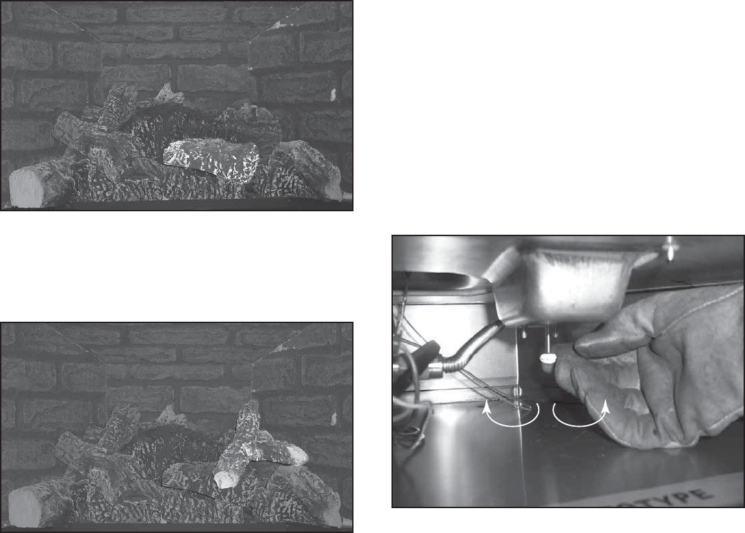
Heatilator • Novus NNXT • 4055-879 • Rev. o • 2/1262
Figure 15.10 Instell Right Middle Log
• Install the Right middle log by aligning the slot and hole
in the bottom of the log with the two pins on the right
end of the left bottom log.
Figure 15.11 Install Top Right Y Log
• Install the top right Y log by aligning the slot on the bottom
of the log with the pin on the right side of the back log.
The Y end of the log should rest on the top indent in the
right middle log and the top of the right bottom log.
M. Replacing Fixed Glass Assembly
• Set the glass panel on the lower two or four glass
assembly latches, ensuring the glass panel is centered
in the opening.
• Replace glass latches. See Figure 15.4.
N. Air Shutter Setting
Air shutter setting should be adjusted by a qualifi ed in-
staller at the time of installation.
• The air shutter is set at the factory for minimum vertical
vent run.
• Adjust air shutter for longer vertical runs. See
Figure 15.12.
• Turn the thumbscrew to open and close.
OpenClose
Figure 15.12 Adjusting Air Shutter
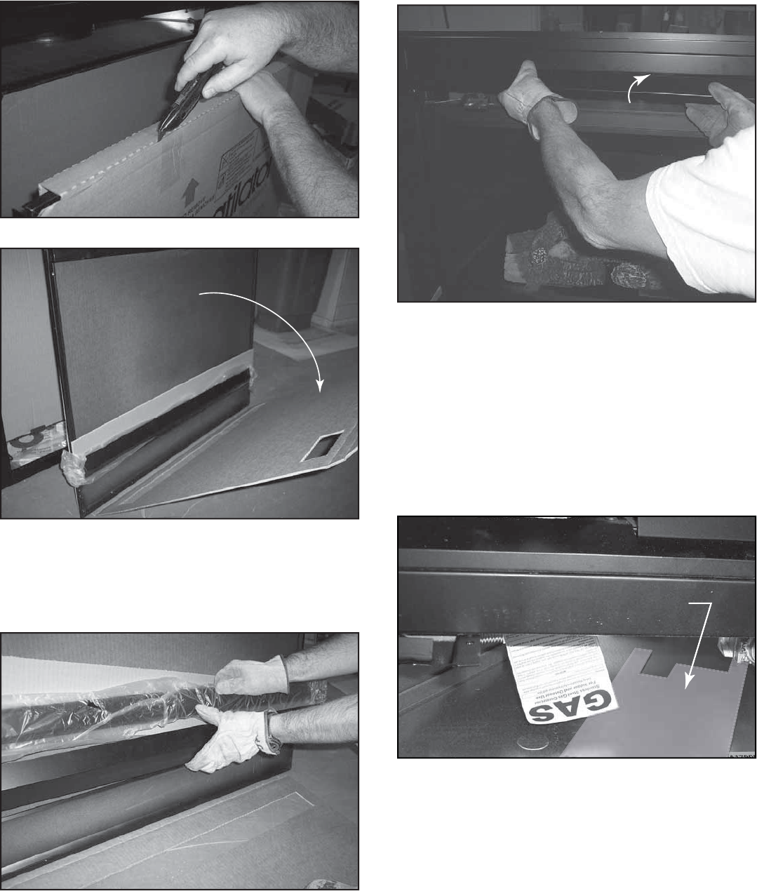
63Heatilator • Novus NNXT • 4055-879 • Rev. o • 2/12
Q. Install Hood
• Locate the four screws just inside the upper section of
the appliance.
• Slide the hood into position uncer the screw heads.
• Tighten the four screws. See Figure 15.16.
P. Unpackage the Hood & Floor Cover
Remove parts package from appliance as shown in Fig-
ure 5.15.
Figure 15.5 Removing Parts Package
Figure 15.16 Intalling Hood
O. Remove Screen Protector
• Cut the tape on top of the screen protector. See
Figure 15.13.
• Open the screen protector and remove the screen. See
Figure 15.14.
Figure 15.14 Remove Screen Protector
Figure 15.13 Cut Packaging Tape
R. Install Control Heat Shield
The control heat shield shipped in the bottom of the ap-
pliance MUST be placed over the control plate before
operating the appliance. Not doing so may result in over-
heating the controls on the plate.
Install the Control Heat Shield
• Locate control heat shield (see Figure 15.17) and remove
from appliance.
Control Heat Shield
Figure 15.17 Locate Control Heat Shield
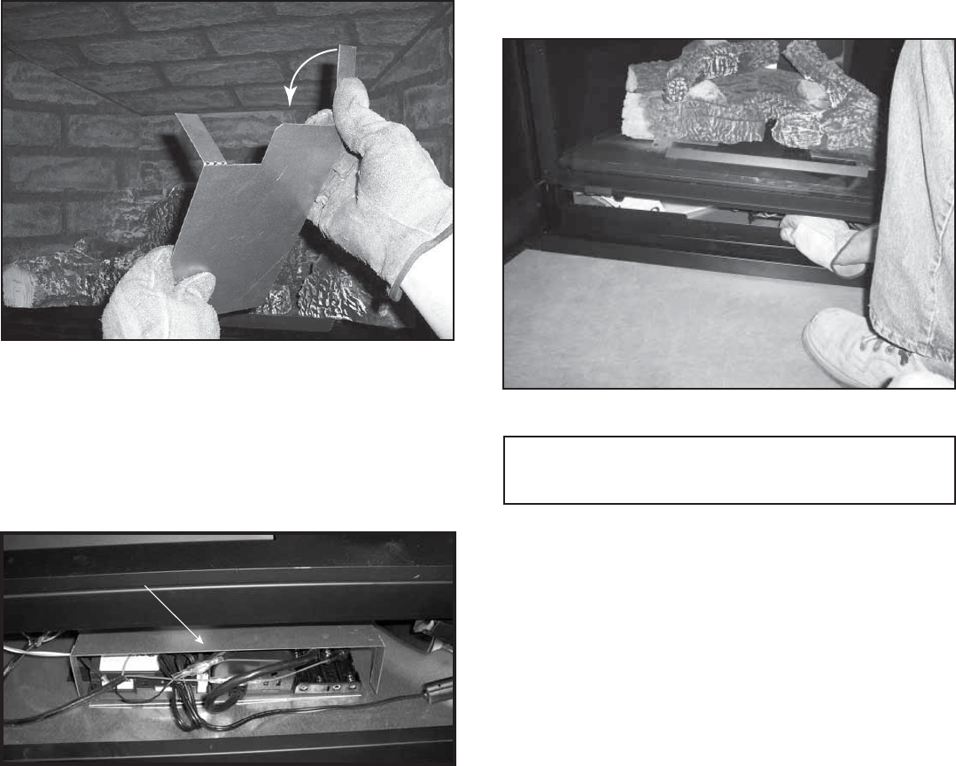
Heatilator • Novus NNXT • 4055-879 • Rev. o • 2/1264
S. Install Floor Cover
Install the fl oor cover as shown in Figure 15.20.
Figure 15.20 Installing Floor Cover
Note: The fl oor cover in the bottom front of the fi replace
may be covering the UL labels. It is loose and can be
removed/replaced.
• Bend four legs at 90° angle as shown in Figure 15.18.
Bend to a 90° angle
Figure 15.18 Bend Control Heat Shield Legs
• Place over control plate so that all of the control plate is
covered and legs are on bottom pan of appliance. See
Figure 15.19.
Figure 15.19 Control Heat Shield - Installed
• Make sure all wires are under the top of the control heat
shield and that there are no wires pinched between legs
and the bottom pan.
Control Heat Shield in Place
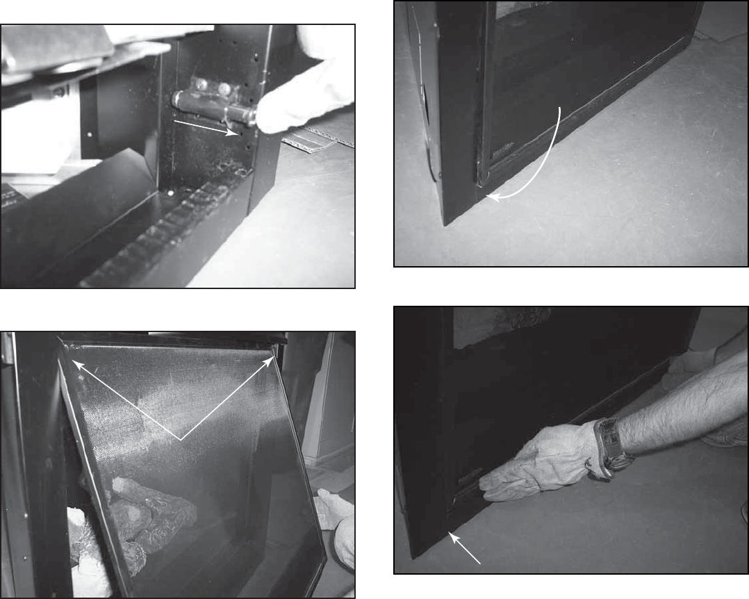
65Heatilator • Novus NNXT • 4055-879 • Rev. o • 2/12
T. Close the Screen Assembly
• Make sure the screen magnetic touch latches are in the
open position. See Figure 15.21.
• Hange the screen on the shoulder screws in the columns.
See Figure 15.22.
Open
Figure 15.21 Magnetic Touch Latch Open
Hang Screen on Shoulder Screws
Figure 15.22 Hang Screen
• Rotate the screen in at the bottom until it touches the
magnetic touch latches. See Figure 15.23.
• Press in on the bottom of the screen until the magnetic
touch latches close. See Figure 15.24.
Figure 15.23 Rotate the Screen Down
Figure 15.24 Press on Bottom of Screen
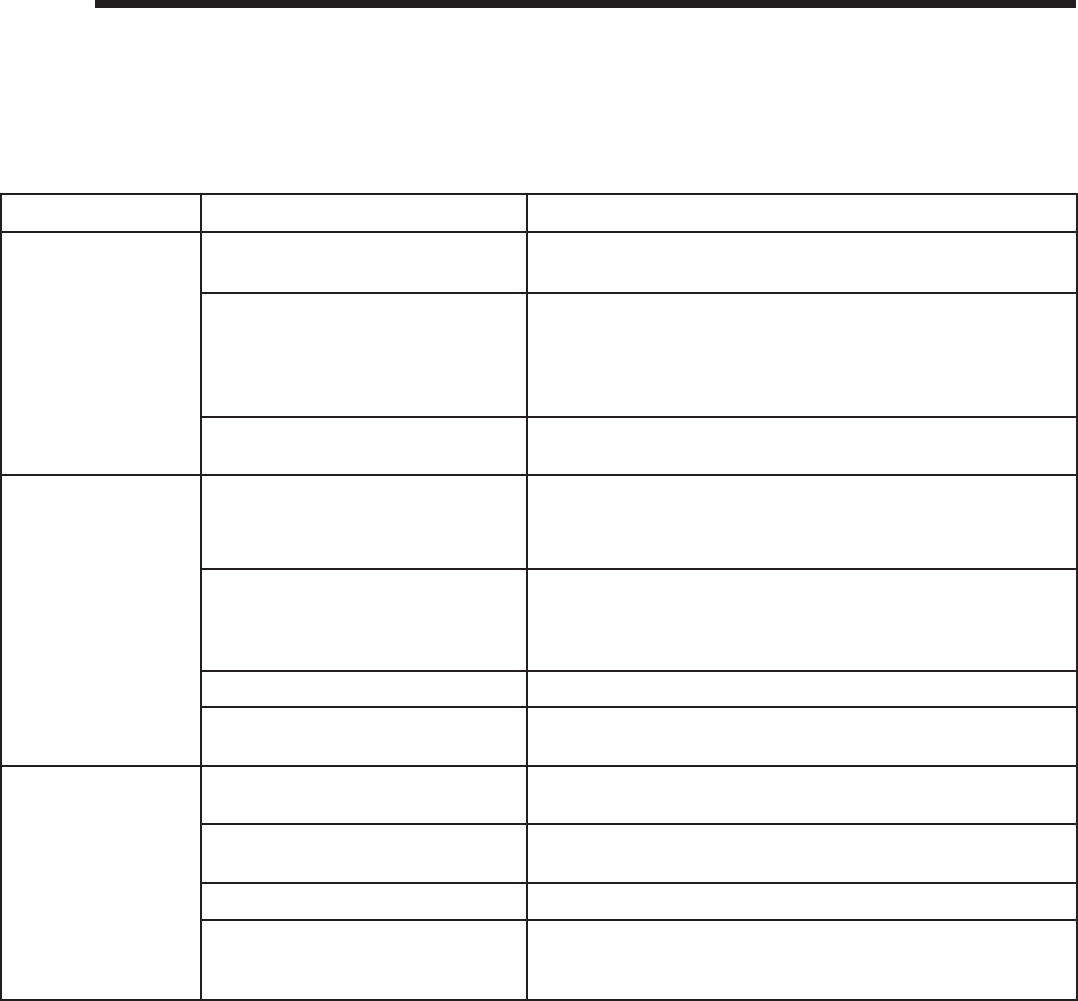
Heatilator • Novus NNXT • 4055-879 • Rev. o • 2/1266
16
16 Troubleshooting
With proper installation, operation, and maintenance your gas appliance will provide years of trouble-free service. If you
do experience a problem, this troubleshooting guide will assist a qualifi ed service technician in the diagnosis of a problem
and the corrective action to be taken. This troubleshooting guide can only be used by a qualifi ed service technician. Con-
tact your dealer to arrange a service call by a qualifi ed service technician.
A. Intellifi re Plus™ Intermittent Ignition System
Symptom Possible Cause Corrective Action
1. Pilot won’t light.
The ignitor/module
makes noise, but no
spark.
A. Incorrect wiring. Verify “S” wire (white) for sensor and “I” wire (orange) for ignitor are
connected to correct terminals on module and pilot assembly.
B. Loose connections or electrical
shorts in the wiring. Verify no loose connections or electrical shorts in wiring from mod-
ule to pilot assembly. Verify connections underneath pilot assembly
are tight; also verify igniter and fl ame sense wires are not grounding
out to metal chassis, pilot burner, pilot enclosure, mesh screen if
present, or any other metal object.
C. Ignitor gap is too large. Verify gap of igniter to right side of pilot hood. The gap should be
approximately .17 in. or 1/8 in. (3 mm).
2. Pilot won’t light,
there is no noise or
spark.
A. No power or transformer installed
incorrectly. Verify that transformer is installed and plugged into module. Check
voltage of transformer at connection to module. Acceptable read-
ings of a good transformer are between 6.4 and 6.6 volts AC.
B. A shorted or loose connection in
wiring confi guration or wiring har-
ness.
Remove and reinstall the wiring harness that plugs into module.
Verify there is a tight fi t. Verify pilot assembly wiring to module. Re-
move and verify continuity of each wire in wiring harness. Replace
any damaged components.
C. Improper wall switch wiring. Verify that 120/VAC power is “ON” to junction box.
D. Module not grounded. Verify black ground wire from module wire harness is grounded to
metal chassis of appliance.
3. Pilot sparks, but
Pilot will not light. A. Gas supply. Verify that incoming gas line ball valve is “open”. Verify that inlet
pressure reading is within acceptable limits.
B. Ignitor gap is too large. Verify gap of igniter to right side of pilot hood. The gap should be
approximately .17 in. or 1/8 in. (3 mm).
C. Module is not grounded. Verify module is securely grounded to metal chassis of appliance.
D. Pilot valve solenoid Verify that 1.5 to 1.8 VDC is supplied to pilot solenoid from module.
If below 1.5 volts, replace module. If 1.5 volts or greater, replace
valve.

67Heatilator • Novus NNXT • 4055-879 • Rev. o • 2/12
Intellifi re Plus Intermittent Pilot Ignition System - (continued)
4. Pilot lights but con-
tinues to spark, and
main burner will not
ignite. (If the pilot
continues to spark
after the pilot fl ame
has been lit, fl ame
rectifi cation has not
occurred.)
A. A shorted or loose connection in
fl ame sensing rod. Verify all connections to wiring diagram in manual. Verify connec-
tions underneath pilot assembly are tight. Verify fl ame sense or ig-
niter wires are not grounding out to metal chassis, pilot burner, pilot
enclosure or screen if present, or any other metal object.
B. Poor fl ame rectifi cation or contami-
nated fl ame sensing rod. With fi xed glass assembly in place, verify that fl ame is engulfi ng
fl ame sensing rod on left side of pilot hood. Flame sensing rod
should glow shortly after ignition. With a multi-meter, verify that
current in series between module and sense lead is at least 0.14
microamps. Verify correct pilot orifi ce is installed and gas inlet is set
to pressure specifi cations. Polish fl ame sensing rod with fi ne steel
wool to remove any contaminants that may have accumulated on
fl ame sensing rod.
C. Module is not grounded. Verify module is securely grounded to metal chassis of appliance.
Verify that wire harness is fi rmly connected to the module.
D. Damaged pilot assembly or con-
taminated fl ame sensing rod. Verify that ceramic insulator around the fl ame sensing rod is not
cracked, damaged, or loose. Verify connection from fl ame sensing
rod to white sensor wire. Polish fl ame sensing rod with fi ne steel
wool to remove any contaminants that may have accumulated on
fl ame sensing rod. Verify continuity with a multi-meter with ohms set
at lowest range. Replace pilot if any damage is detected.
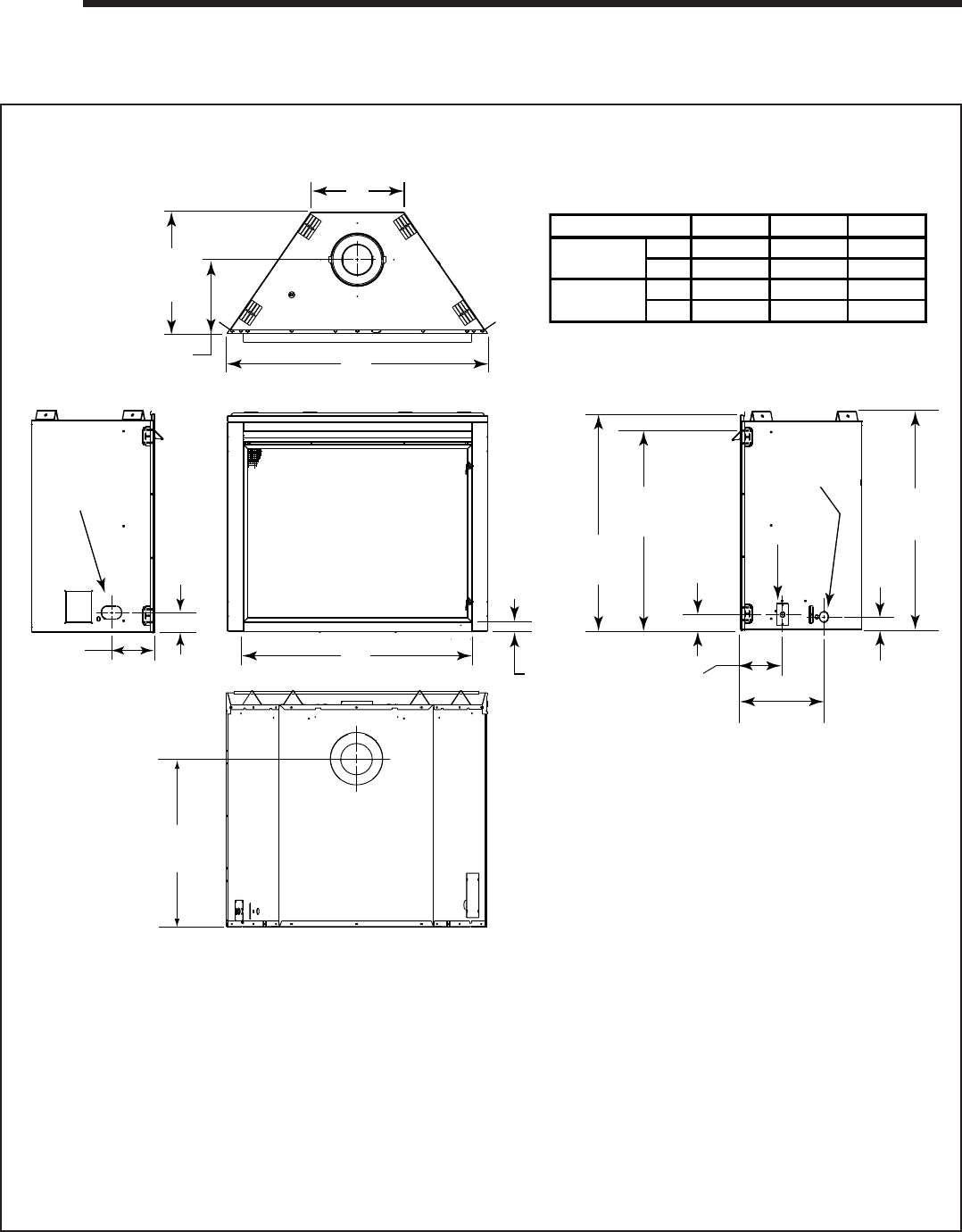
Heatilator • Novus NNXT • 4055-879 • Rev. o • 2/1268
17
17 Reference Materials
Electrical
Access
Alternative
Gas Access
1-3/4 in.
(44 mm)
34-1/2 in.
(876 mm)
1-1/2 in.
(38 mm)
15-3/4 in.
(400 mm)
8 in.
(203 mm)
2-3/8 in.
(60 mm)
31-1/2 in.
(800 mm)
34 in.
(864 mm)
A
B
23-1/2 in.
(597 mm)
6-1/2 in.
(165 mm)
C
19-1/8 in.
(486 mm)
11-5/8in.
(295 mm)
Gas Line
Access
3 in.
(76 mm)
Model A B C
in. 38 33 11 5/8
mm 965 838 295
in. 41 36 14 5/8
mm 1041 916 371
NNXT3933
NNXT4236
A. Appliance Dimension Diagram
Dimensions are actual appliance dimensions. Use for reference only. For framing dimensions and clearances refer to Section 5.
Figure 17.1 Appliance Dimensions
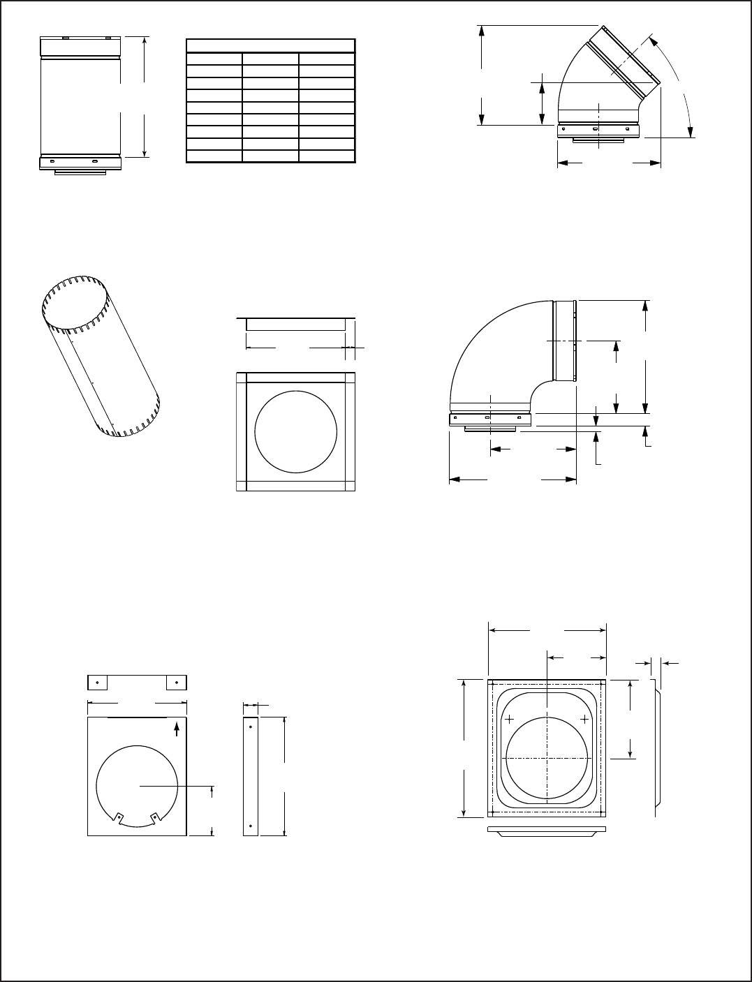
69Heatilator • Novus NNXT • 4055-879 • Rev. o • 2/12
B. Vent Components Diagrams
Figure 17.2 DVP Vent Components
Effective
Height/Length
DVP Pipe
(see chart)
Pipe
inches mm
DVP4 4 102
DVP6 6 152
DVP12 12 305
DVP24 24 610
DVP36 36 914
DVP48 48 1219
DVP6A 3 - 6 76 - 152
DVP12A 3 - 12 76 - 305
Effective Height/Length
10-1/2 in.
(267 mm)
10-7/8 in.
(276 mm)
DVP45
45° Elbow
45°
4-7/8 in.
(124 mm)
Assembled
Height: 24 in./610 mm
Diameter: 10 in./254 mm
DVP-AS2
10 in.
(254 mm)
1 in.
(25 mm)
DVP-FS
Ceiling Firestop
7-3/8 in.
(187 mm)
11-3/8 in.
(289 mm)
1-1/4 in.
(32 mm)
9-1/4 in.
(235 mm)
13-1/4 in.
(337 mm)
1/2 in.
(13 mm) TYP
DVP90ST
90° Elbow
10 in.
(254 mm)
1-1/2 in.
(38 mm)
5 in.
(127 mm)
12 in.
(305 mm)
DVP-HVS
Vent Support
UP
DVP-WS
Wall Shield Firestop
14 in.
(356 mm)
1 in.
(25 mm)
8 in.
(203 mm)
6 in.
(152 mm)
12 in.
(305 mm)
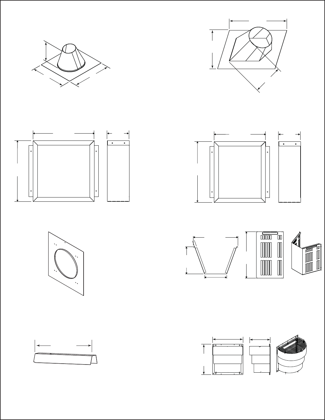
Heatilator • Novus NNXT • 4055-879 • Rev. o • 2/1270
B. Vent Components Diagrams (continued)
Figure 17.3 DVP Vent Components
13-1/4 in.
(367 mm)
24-5/8 in.
(625 mm)
27-1/2 in.
(698 mm)
RF6M
Roof Flashing Multi-pak
31 in.
(787 mm)
24-5/8 in.
(625 mm)
13-1/4 in.
(367 mm)
RF12M
Roof Flashing Multi-pak
BEK
Trap Cap Brick Extension
13-3/4 in.
(349 mm)
5 in.
(127 mm)
13-3/4 in.
(349 mm)
DVP-BEK2
DVP-HPC Cap Brick Extension
13-7/8 in.
(352 mm)
5 in.
(127 mm)
11-7/8 in.
(302 mm)
COOL-ADD
Cap Shield
11-5/8 in.
(295 mm)
5-3/4 in.
(146 mm)
7-1/8 in.
(181 mm)
12-1/8 in.
(308 mm)
DRC-RADIUS
Cap Shield
13-7/8 in.
(352 mm) 9-1/2 in.
(241 mm)
14 in.
(356 mm)
DVP-TRAPFL
Flashing
26 in.
(660 mm)
DVP-HSM-B
Extended Heat Shield
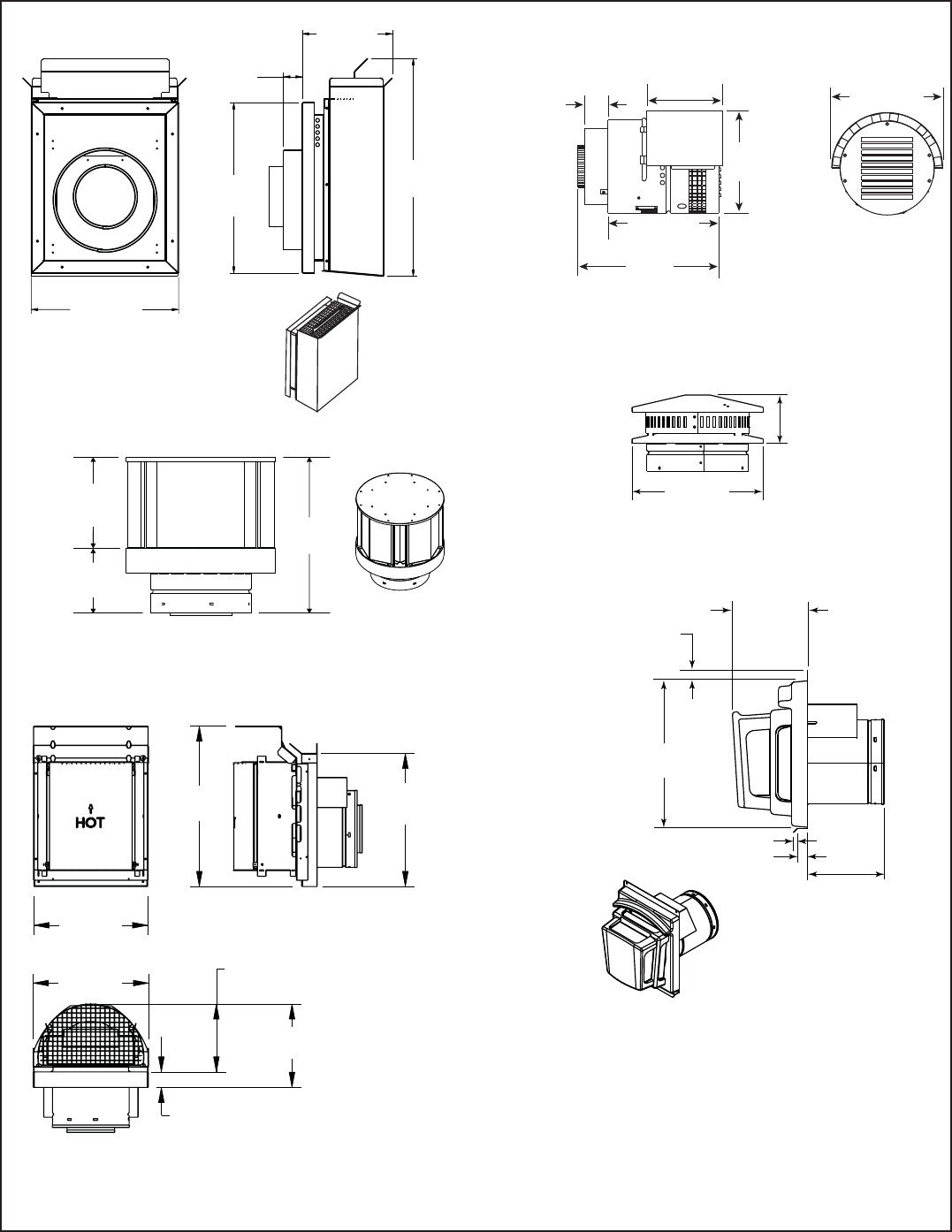
71Heatilator • Novus NNXT • 4055-879 • Rev. o • 2/12
B. Vent Components Diagrams (continued)
Figure 17.4 DVP Vent Components
DVP-TB1
Basement Vent Cap
12 in.
(305 mm)
1-1/2 in.
(38 mm)
7-3/8 in.
(187 mm)
14 in.
(356 mm)
17-3/4 in.
(451 mm)
10-1/2 in.
(267 mm)
3-7/8 in.
(98 mm)
DVP-TV
Vertical Termination Cap
1 in.
(25 mm)
14 in.
(356 mm)
3/8 in. (10 mm)
1 in. (25 mm)
7-1/4 in.
(184 mm)
7-3/4 to 10-3/8 in.
(197 to 264 mm)
DVP-FBHT
Fire Brick Termination Cap
7-1/4 in.
(184 mm)
5-1/4 in.
(133 mm)
12-1/2 in.
(318 mm)
DVP-TVHW
Vertical Termination Cap (High wind)
14 in.
(356 mm)
12 in.
(305 mm)
12-1/8 in.
(314 mm)
7-1/8 in.
(181 mm)
8-3/4 in.
(222 mm)
1-5/8 in.
(41 mm)
16-7/8 in.
(429 mm)
DVP-HPC
High Performance Cap
PVK-80
(For use with IPI and DSI appliances only.)
11-1/2 in.
(280 mm)
12-1/2 in.
(317 mm)
16 in.
(406 mm)
9 in.
(229 mm)
2-3/4 in.
(70 mm)
12-1/4 in.
(311 mm)
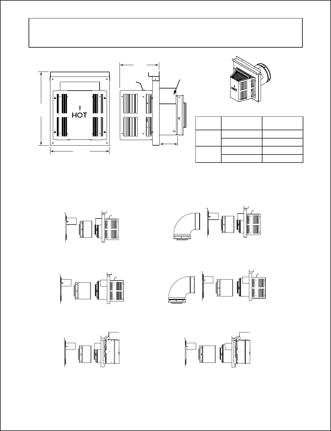
Heatilator • Novus NNXT • 4055-879 • Rev. o • 2/1272
B. Vent Components Diagrams (continued)
Figure 17.5 DVP Vent Components
DVP-TRAP1
DVP-TRAP2
DVP-HPC1 DVP-HPC2
DVP-TRAPK1
DVP-TRAPK2
DVP-TRAP
Horizontal Termination Cap
15-1/8 in.
(384 mm)
12 in.
(305 mm)
8 in.
(203 mm)
Max
Effective
Length
Note: Heat shields MUST overlap by a minimum of 1-1/2 in. (38 mm). The heat shield is designed to be
used on a wall 4 in. to 7-1/4 in. (102 mm to 184 mm) thick. If wall thickness is less than 4 in. (102 mm) the
existing heat shields must be field trimmed. If wall thickness is greater than 7-1/4 in. (184 mm) a DVP-HSM-B
will be required.
Heat
Shield
Term Cap Minimum
Effective Length Maximum
Effective Length
Trap1 3-1/8 in. 4-5/8 in.
79 mm 117 mm
Trap2 5-3/8 in. 9-3/8 in.
137 mm 238 mm
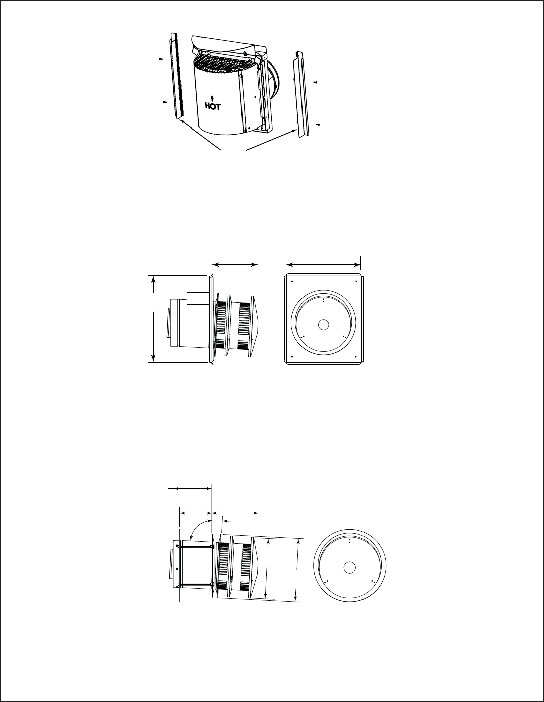
73Heatilator • Novus NNXT • 4055-879 • Rev. o • 2/12
B. Vent Components Diagrams (continued)
Figure 17.6 DVP Vent Components
13 in.
(330 mm)
15 in.
(381 mm)
8-1/8 in.
(206 mm)
DVP-HRC-SS
10-7/8 in.
276 mm
10-1/2 in.
267 mm
3°
87°
Effective Length
5-3/4 to 8-3/8 in.
146 to 213 mm
5-1/2 in.
140 mm 8-3/8 in.
213 mm
DVP-HRC-ZC-SS
Fillers
DVP-TRAP to DVP-HPC Side Filler Kit
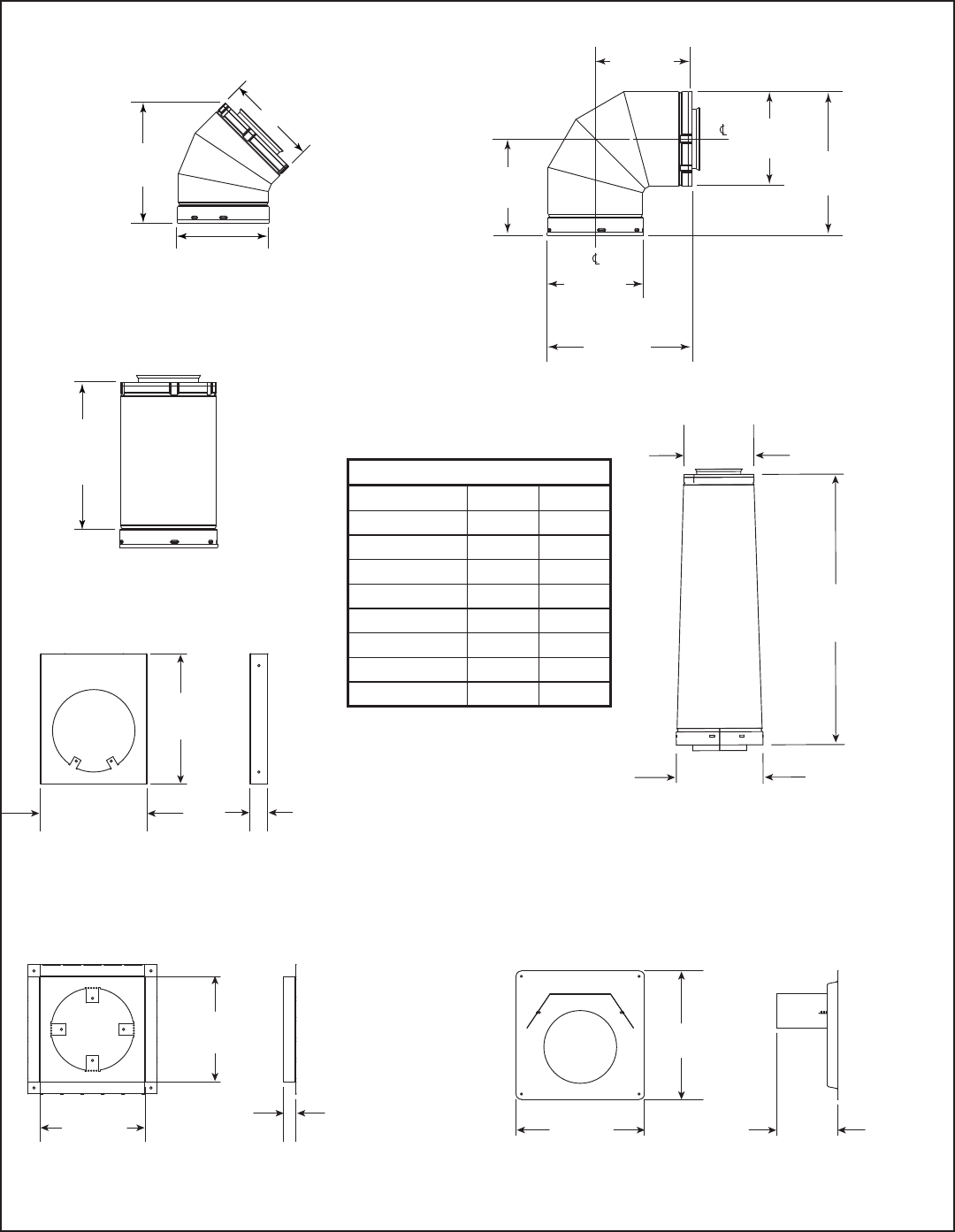
Heatilator • Novus NNXT • 4055-879 • Rev. o • 2/1274
B. Vent Components Diagrams (continued)
Figure 17.7 SLP Series Vent Components
Effective Height/Length
Pipe inches mm
SLP4 4 102
SLP6 6 152
SLP12 12 305
SLP24 24 610
SLP36 36 914
SLP48 48 1219
SLP6A 2 - 6 51 - 152
SLP12A 2 - 12 51 - 305
8-3/4 in.
222 mm
6-1/2 in.
165 mm
6-5/8 in.
168 mm
6 in.
152 mm
6-1/2 in.
165 mm
6-5/8 in.
168 mm
9-7/8 in.
251 mm
6-1/2 in.
165 mm
9-1/4 in.
235 mm
SLP45
45° Elbow
SLP90-ST
90° Elbow
Effective
Height/
Length
SLP PIPE
SLP-HVS
Horizontal Pipe
Support
SLP-FS
Ceiling Firestop SLP-WS
Wall Shield Firestop
DVP-SLP24
Adapter
6-1/2 in.
165 mm
25-3/16 in.
640 mm
8-1/16 in.
205 mm
10-7/8 in.
276 mm
8-7/8 in.
225 mm
1-1/2 in.
38 mm
8-11/16 in.
220 mm
8-11/16 in.
220 mm
1-1/2 in.
38 mm 12 in.
305 mm
12 in.
305 mm
5-1/2 in.
146 mm
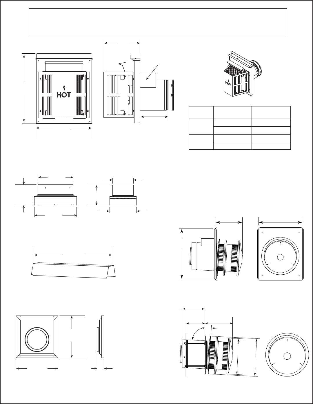
75Heatilator • Novus NNXT • 4055-879 • Rev. o • 2/12
SLP-WT-BK
Wall Thimble-Black
SL-2DVP
Adapter
26 in.
660 mm
DVP-HSM-B
Extended Heat Shield
SLP-TRAP
Horizontal Termination Cap
15-1/8 in.
(384 mm)
Note: Heat shields MUST overlap by a minimum of 1-1/2 in. (38 mm). The heat shield is designed to be
used on a wall 4 in. to 7-1/4 in. (102 mm to 184 mm) thick. If wall thickness is less than 4 in. (102 mm)
the existing heat shields must be field trimmed. If wall thickness is greater than 7-1/4 in. (184 mm) a
DVP-HSM-B will be required.
Heat
Shield
Term Cap Minimum
Effective Length Maximum
Effective Length
Trap1 3-1/8 in. 4-3/4 in.
79 mm 121 mm
Trap2 5-1/4 in. 9-1/4 in.
133 mm 235 mm
8 in.
(203 mm)
12 in.
(305 mm)
Max
Effective
Length
14-7/16 in.
367 mm
14-7/16 in.
367 mm
2-5/16 in.
59 mm
3-15/16 in.
(101 mm)
6-11/16 in.
(169 mm)
8 in.
(203 mm)
3-15/16 in.
(101 mm)
3-13/16 in.
(97 mm)
5-1/16 in.
(128 mm)
B. Vent Components Diagrams (continued)
13 in.
(330 mm)
15 in.
(381 mm)
8-1/8 in.
(206 mm)
SLP-HRC-SS
10-7/8 in.
276 mm
10-1/2 in.
267 mm
3°
87°
Effective Length
5-3/4 to 8-3/8 in.
146 to 213 mm
5-1/2 in.
140 mm 8-3/8 in.
213 mm
SLP-HRC-ZC-SS
Figure 17.8 SLP Series Vent Components
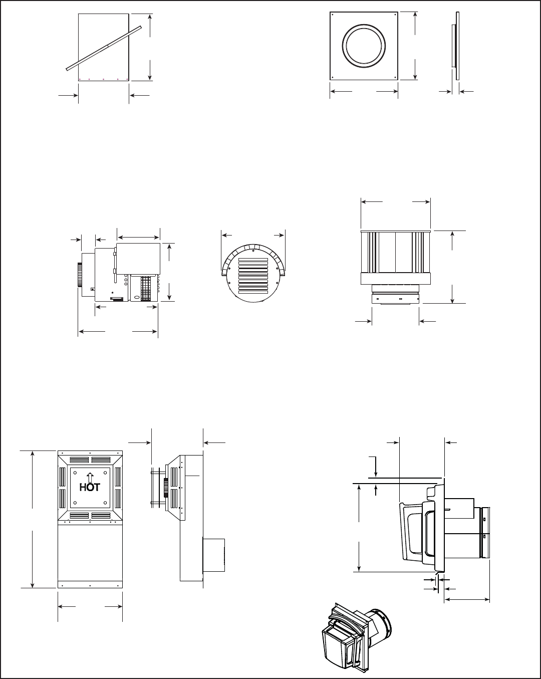
Heatilator • Novus NNXT • 4055-879 • Rev. o • 2/1276
1 in.
(25 mm)
14 in.
(356 mm)
3/8 in. (10 mm)
1 in. (25 mm)
7-1/4 in.
(184 mm)
7-3/4 to 10-3/8 in.
(197 to 264 mm)
13 in.
330 mm
13 in.
330 mm
1-5/16 in.
34 mm
10-9/16 in.
269 mm
14 in.
356 mm
12-1/2 in.
318 mm
8-1/16 in.
205 mm
12 in.
305 mm
SLP-CCS-BK
Cathedral Ceiling
Support Box-Black
SLP-DCF-BK
Ceiling Firestop
Black
SLK-SNKD
Snorkel
Termination Cap
SLP-TVHW
Vertical
Termination Cap
DVP-FBHT
Horizontal
Termination Cap
13-1/2 in.
343 mm
28-1/2 in.
724 mm
10-11/16 in.
271mm
PVK-80
(For use with IPI and DSI appliances only.)
11-1/2 in.
(280 mm)
12-1/2 in.
(317 mm)
16 in.
(406 mm)
9 in.
(229 mm)
2-3/4 in.
(70 mm)
12-1/4 in.
(311 mm)
Figure 17.9 SLP Series Vent Components
B. Vent Components Diagrams (continued)
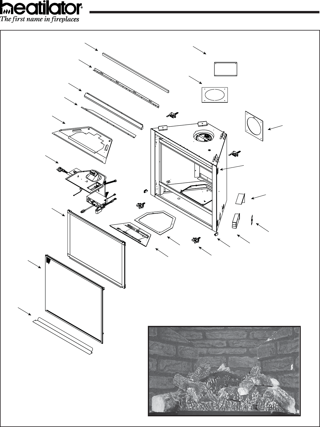
77Heatilator • Novus NNXT • 4055-879 • Rev. o • 2/12
C. Service Parts
Novus DV Heater IPI Appliance Beginning Manufacturing Date: Aug 2009
Ending Manufacturing Date: ______
NNXT3933I, NNXT4236I
Part number list on following page.
8
8
10
11
12
13
14
15
16
17
18
19
20
21 22 23
24
25
07
26
4
75
61
2
3
Log Set Assembly
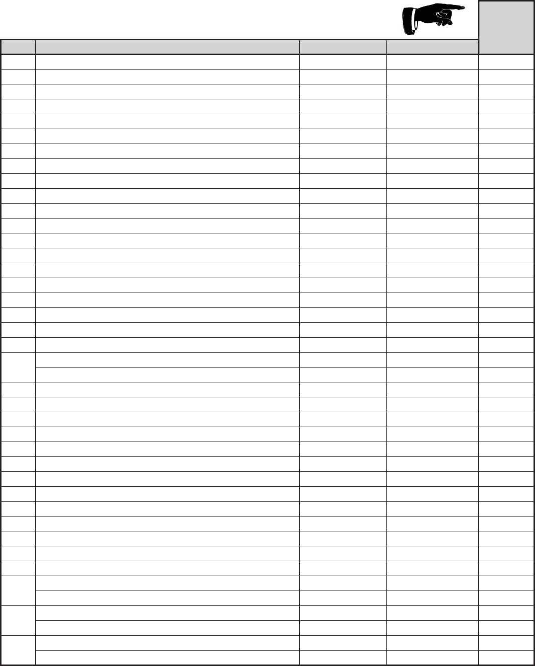
Heatilator • Novus NNXT • 4055-879 • Rev. o • 2/1278
NNXT3933I, NNXT3933IL
C. Service Parts (continued)
IMPORTANT: THIS IS DATED INFORMATION. When requesting service or replacement parts for
your appliance please provide model number and serial number. All parts listed in this manual may
be ordered from an authorized dealer. Stocked
at Depot
ITEM DESCRIPTION COMMENTS PART NUMBER
Log Assembly 4055-976 Y
1Back Log SRV4055-966
2Bottom Right Log SRV4055-967
3Bottom Left Log SRV4055-969
Log Assembly, Top and Middle SRV4055-974
4Middle Right Log SRV4055-970
5Top Right Log SRV4055-971
6Middle Left Log SRV4055-972
7Top Left Log SRV4055-973
8 Intake Cover Gasket 25844
9 Intake Cover Gasket 4031-239
10 Non Combustible Board 4055-895
11 Dry Wall Lip 4055-893
12 Hood 4055-215
13 Heater Baffl e 4055-881
14 Hearth Pan 4055-874
15 Valve Assembly Refer to valve page.
16 Glass Frame Assembly GLA4000-307 Y
17 Screen Assembly SRV4055-991 Y
18 Floor Cover 4055-274
19 Burner Assembly NG 4055-882 Y
Burner Assemlby LP 4055-896 Y
20 Gasket Valve Plate 4055-135
21 Glass Latch Assembly Pkg of 2 33858/2 Y
22 Magnetic Touch Latch Qry 2 req 4021-650 Y
23 Junction Box 4021-013 Y
24 Cover Plate 4031-222
25 Junction Box Shield 4055-888
26 Nailing Flange Qty 4 req 4044-161
27 Back Gasket 4000-225
Cord Clip 14218
Refractory, Back 4055-856
Refractory, Right Side 4055-859
Refractory, Left Side 4055-860
Refractory, Top 4055-866
Conversion Kit NG DCKVN-NNXT Y
Conversion Kit LP DCKVP-NNXT Y
Pilot Orifi ce NG 593-528 Y
Pilot Orifi ce LP 593-527 Y
Regulator NG NGK-DXV-50 Y
Regulator LP LPK-DXV-50 Y
Additional service parts on following page.
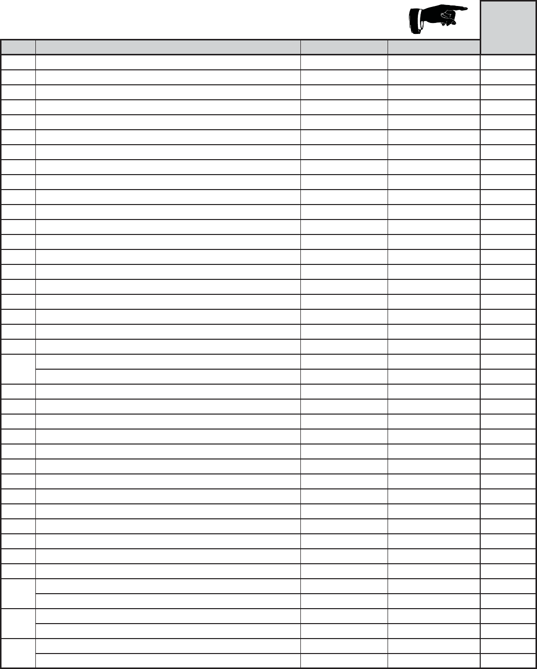
79Heatilator • Novus NNXT • 4055-879 • Rev. o • 2/12
IMPORTANT: THIS IS DATED INFORMATION. When requesting service or replacement parts for
your appliance please provide model number and serial number. All parts listed in this manual may
be ordered from an authorized dealer. Stocked
at Depot
ITEM DESCRIPTION COMMENTS PART NUMBER
Log Assembly 4055-976 Y
1Back Log SRV4055-966
2Bottom Right Log SRV4055-967
3Bottom Left Log SRV4055-969
Log Assembly, Top and Middle SRV4055-974
4Middle Right Log SRV4055-970
5Top Right Log SRV4055-971
6Middle Left Log SRV4055-972
7Top Left Log SRV4055-973
8 Intake Cover Gasket 25844
9 Intake Cover Gasket 4031-239
10 Non Combustible Board 4055-895
11 Dry Wall Lip 4055-893
12 Hood 4055-215
13 Heater Baffl e 4055-881
14 Hearth Pan 4055-874
15 Valve Assembly Refer to valve page.
16 Glass Frame Assembly GLA4000-307 Y
17 Screen Assembly SRV4055-991 Y
18 Floor Cover 4055-274
19 Burner Assembly NG 4055-882 Y
Burner Assemlby LP 4055-896 Y
20 Gasket Valve Plate 4055-135
21 Glass Latch Assembly Pkg of 2 33858/2 Y
22 Magnetic Touch Latch Qry 2 req 4021-650 Y
23 Junction Box 4021-013 Y
24 Cover Plate 4031-222
25 Junction Box Shield 4055-888
26 Nailing Flange Qty 4 req 4044-161
27 Back Gasket 4000-225
Cord Clip 14218
Refractory, Back 4055-856
Refractory, Right Side 4055-859
Refractory, Left Side 4055-860
Refractory, Top 4055-866
Conversion Kit NG DCKVN-NNXT Y
Conversion Kit LP DCKVP-NNXT Y
Pilot Orifi ce NG 593-528 Y
Pilot Orifi ce LP 593-527 Y
Regulator NG NGK-DXV-50 Y
Regulator LP LPK-DXV-50 Y
Additional service parts on following page.
C. Service Parts (continued) NNXT4236I, NNXT4236IL
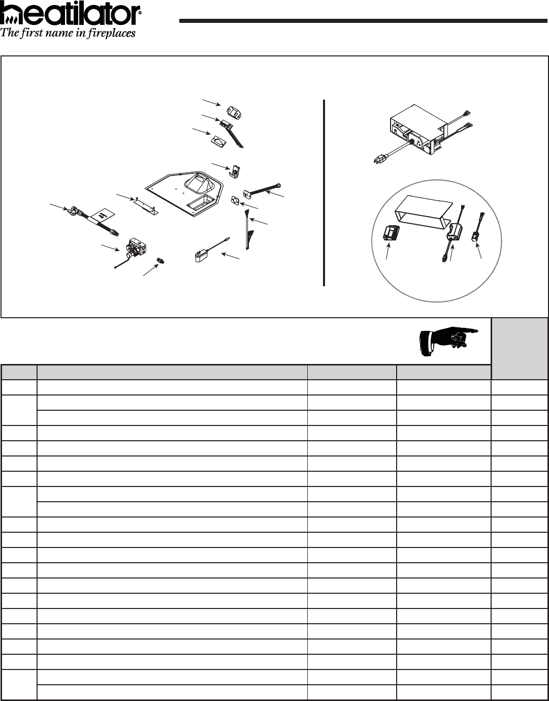
Heatilator • Novus NNXT • 4055-879 • Rev. o • 2/1280
Beginning Manufacturing Date: Aug 2009
Ending Manufacturing Date: ______
NNXT3933I, NNXT4236I
C. Service Parts
IMPORTANT: THIS IS DATED INFORMATION. When requesting service or replacement
parts for your appliance please provide model number and serial number. All parts listed
in this manual may be ordered from an authorized dealer. Stocked
at Depot
ITEM DESCRIPTION COMMENTS PART NUMBER
15.1 Pilot Shield 4055-889
15.2 Pilot Assembly NG 2090-012 Y
Pilot Assembly LP 2090-013 Y
15.3 Pilot Gasket 4021-042
15.4 Air Shutter Assembly 4055-202 Y
15.5 Valve Bracket 4055-205
15.6 Flex Ball Valve Assembly 302-320A Y
15.7 Valve NG 2166-302 Y
Valve LP 2166-303 Y
15.8 Male Connector Pkg of 5 303-315/5 Y
15.9 Transformer 2166-305 Y
15.10 Wire Harness 2166-304 Y
15.11 Gasket, Bulkhead 4021-429
15.12 Bulkhead W/Flex Tube 4021-512 Y
16 Igntion Control Assembly 4055-964 Y
16.1 Control Module 2166-307 Y
16.2 Control Plate 4055-899
16.3 AuxRC200 2166-325 Y
16.4 Battery Pack 2166-323 Y
Orifi ce NG (#39C) 582-839 Y
Orifi ce LP (#52C) 582-852 Y
#15 Valve Assembly
15.1
15.2
15.3
15.4
15.5
15.6
15.7
15.8
15.9
15.10
15.11
15.12
16.1
16.2
16.3 16.4
#16 Ignition Control Assembly
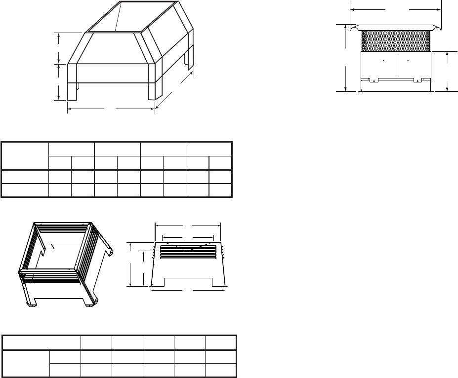
81Heatilator • Novus NNXT • 4055-879 • Rev. o • 2/12
D. Optional Components
A
B
C
D
LDS33/LDS46 Decorative Shroud
E
D
A
CB
LDS-BV Decorative Shroud
20 in.
[508 mm]
17 in.
[432 mm]
9-3/8 in.
[238 mm]
TCG375 Terra Cotta Cap
LDSCP-M Shroud Leg Multipack
(not shown)
See your Heatilator dealer for a complete listing of optional components.
Catalog #
ABCD
in. mm in. mm in. mm in. mm
LDS33 36 914 36 914 8.5 216 11 279
LDS46 48 1219 72 1829 8.5 216 11 279
Catalog # A B C E E
LDS-BV in. 26 12.5 15.5 22 23
mm 660 318 394 533 584

Heatilator • Novus NNXT • 4055-879 • Rev. o • 2/1282
E. Contact Information
- NOTES -
________________________________________________________________________________
________________________________________________________________________________
________________________________________________________________________________
________________________________________________________________________________
________________________________________________________________________________
________________________________________________________________________________
________________________________________________________________________________
________________________________________________________________________________
________________________________________________________________________________
Printed in U.S.A. - Copyright 2012
DO NOT DISCARD THIS MANUAL
NOTICE
• Leave this manual with
party responsible for use
and operation.
• Important operating
and maintenance
instructions included.
• Read, understand and follow
these instructions for safe
installation and operation.
Please contact your Heatilator dealer with any questions or concerns.
For the location of your nearest Heatilator dealer,
please visit www.heatilator.com.
Heatilator, a brand of Hearth & Home Technologies Inc.
7571 215th Street West, Lakeville, MN 55044
www.heatilator.com
This product may be covered by one or more of the following patents: (United States) 5328356, 5601073, 5613487,
5647340, 5890485, 5941237, 5947112, 5996575, 6006743, 6019099, 6053165, 6145502, 6170481, 6374822, 6484712,
6601579, 6769426, 6863064, 7077122, 7098269, 7258116, 7470729 or other U.S. and foreign patents pending. 2000-945
