Helicomm IPLINK12212264 Wireless Module User Manual users manual
Helicomm, Inc. Wireless Module users manual
UserManual.wiki
>
Helicomm
>
IPLINK12212264 User Manual
users manual
Navigation menu
Upload a User Manual
Namespaces
Wiki Guide
HTML
PDF
Info
Views
User Manual
Discussion / Help
Navigation
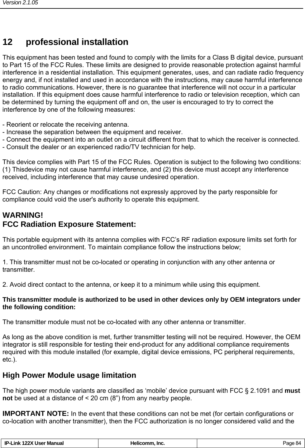
![Version 2.1.05 IP-Link 122X User Manual Helicomm, Inc. Page 72 9 Code of PC obtain the module’s firmware version information ... // Open com port DCB dcb = {0}; HANDLE hCOM = CreateFile(_T("COM1"), GENERIC_READ | GENERIC_WRITE, 0, 0, OPEN_EXISTING, 0, NULL); // Set baud rate dcb.DCBlength = sizeof(DCB); dcb.BaudRate = 38400; dcb.ByteSize = 8; dcb.StopBits = ONESTOPBIT; dcb.Parity = NOPARITY; SetCommState(hCOM, &dcb); ... BYTE btBuf[256]; int i = 0; int nXOR = 0; DWORD dwLen = 0;](https://usermanual.wiki/Helicomm/IPLINK12212264/User-Guide-906821-Page-77.png)
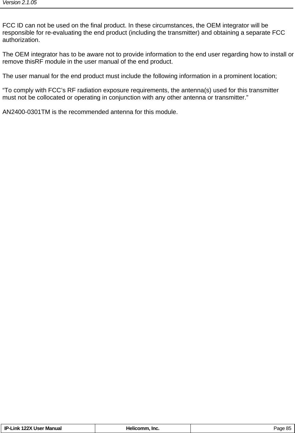
![Version 2.1.05 IP-Link 122X User Manual Helicomm, Inc. Page 73 static int nSN; // Build packet nSN++; btBuf[0] = 0X80 + (0X0F & nSN); // Packet head. btBuf[1] = 0X00; // LQI。 btBuf[2] = 0X00; // High 8 bits of destination address btBuf[3] = 0X01; // Low 8 bits of destination address btBuf[4] = 0X01; // Payload length btBuf[5] = 0X8C; // Payload. Obtain firmware version command // Compute XOR bit by bit for (i = 0, nXOR = 0; i < 6; i++) { nXOR ^= btBuf[i]; } btBuf[6] = nXOR; // XOR bit by bit ... // Send packet WriteFile(hCOM, btBuf, 7, &dwLen, NULL); ...](https://usermanual.wiki/Helicomm/IPLINK12212264/User-Guide-906821-Page-78.png)
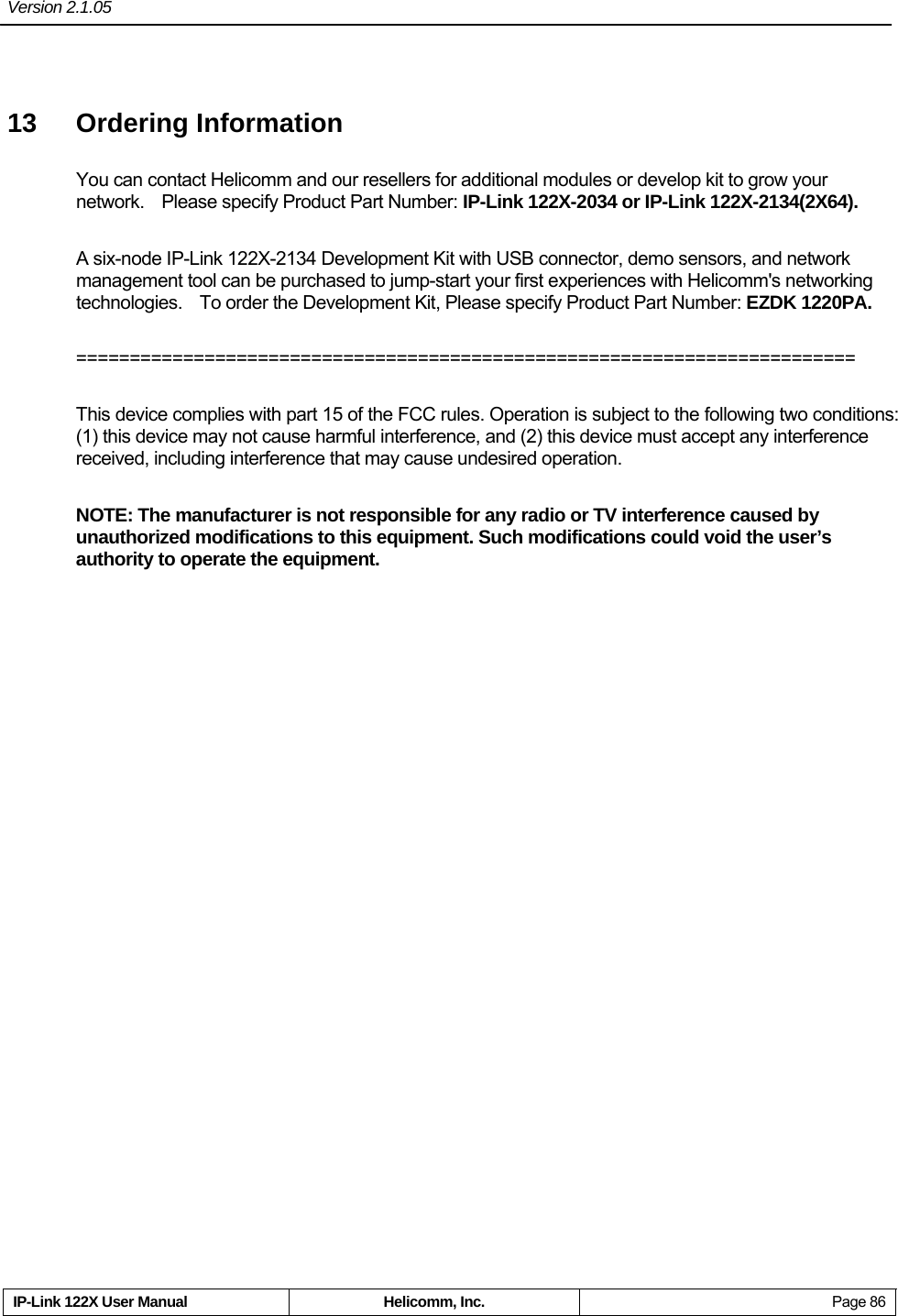
![Version 2.1.05 IP-Link 122X User Manual Helicomm, Inc. Page 74 ZeroMemory(btBuf, sizeof(btBuf)); // Receive Packet ReadFile(hCOM, btBuf, 10, &dwLen, NULL); // Check length if (dwLen != (btBuf[4] + 6)) { ... } // Compute XOR bit by bit for (i = 0, nXOR = 0; i < dwLen; i++) { nXOR ^= btBuf[i]; } // Chenk parity if (0 != nXOR) { ... } // Check packet head if (0XC0 != (btBuf[0] & 0XF0))](https://usermanual.wiki/Helicomm/IPLINK12212264/User-Guide-906821-Page-79.png)
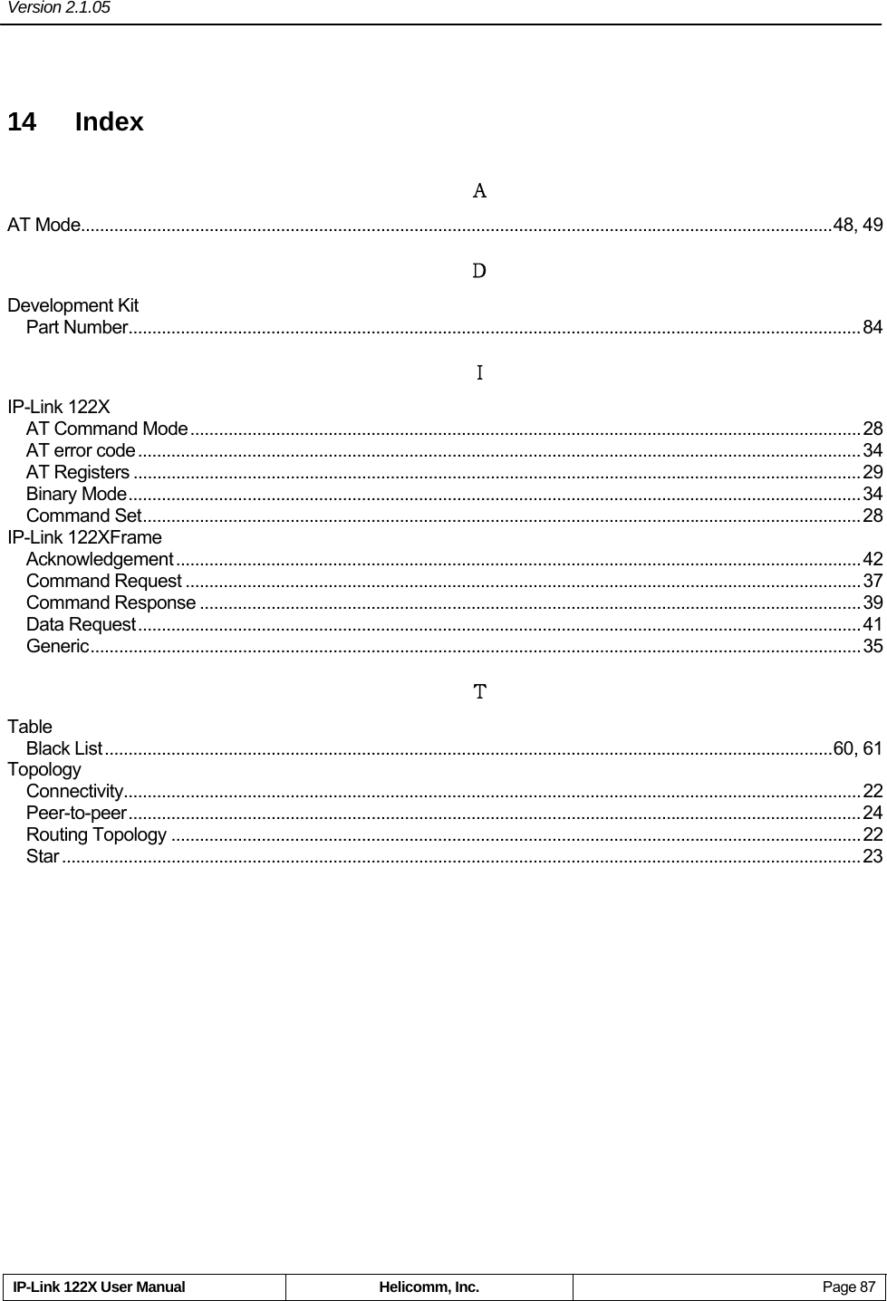
![Version 2.1.05 IP-Link 122X User Manual Helicomm, Inc. Page 75 { ... } // Check command code if (0XFF == btBuf[5]) { ... } ... // btBuf[6] is main version // btBuf[7] is subsidiary version // btBuf[8] is revised version](https://usermanual.wiki/Helicomm/IPLINK12212264/User-Guide-906821-Page-80.png)