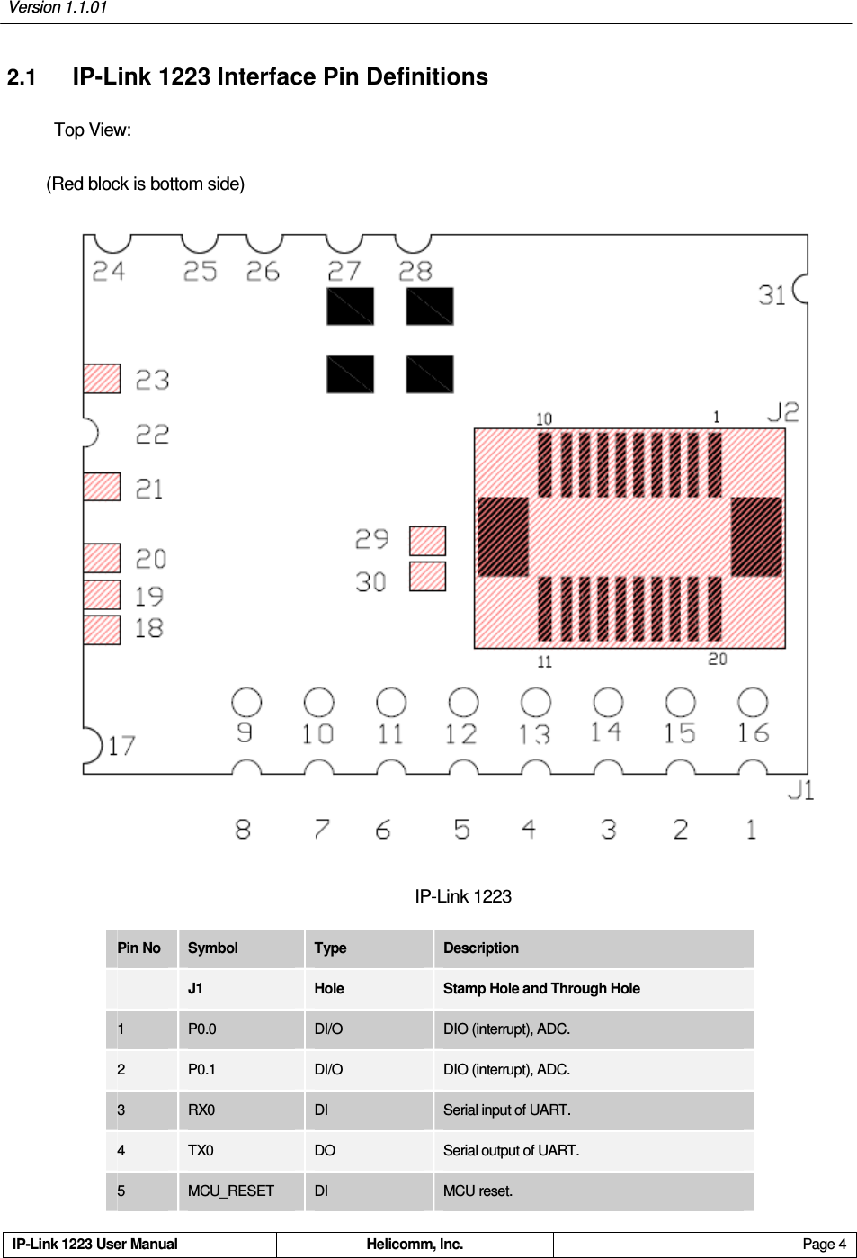
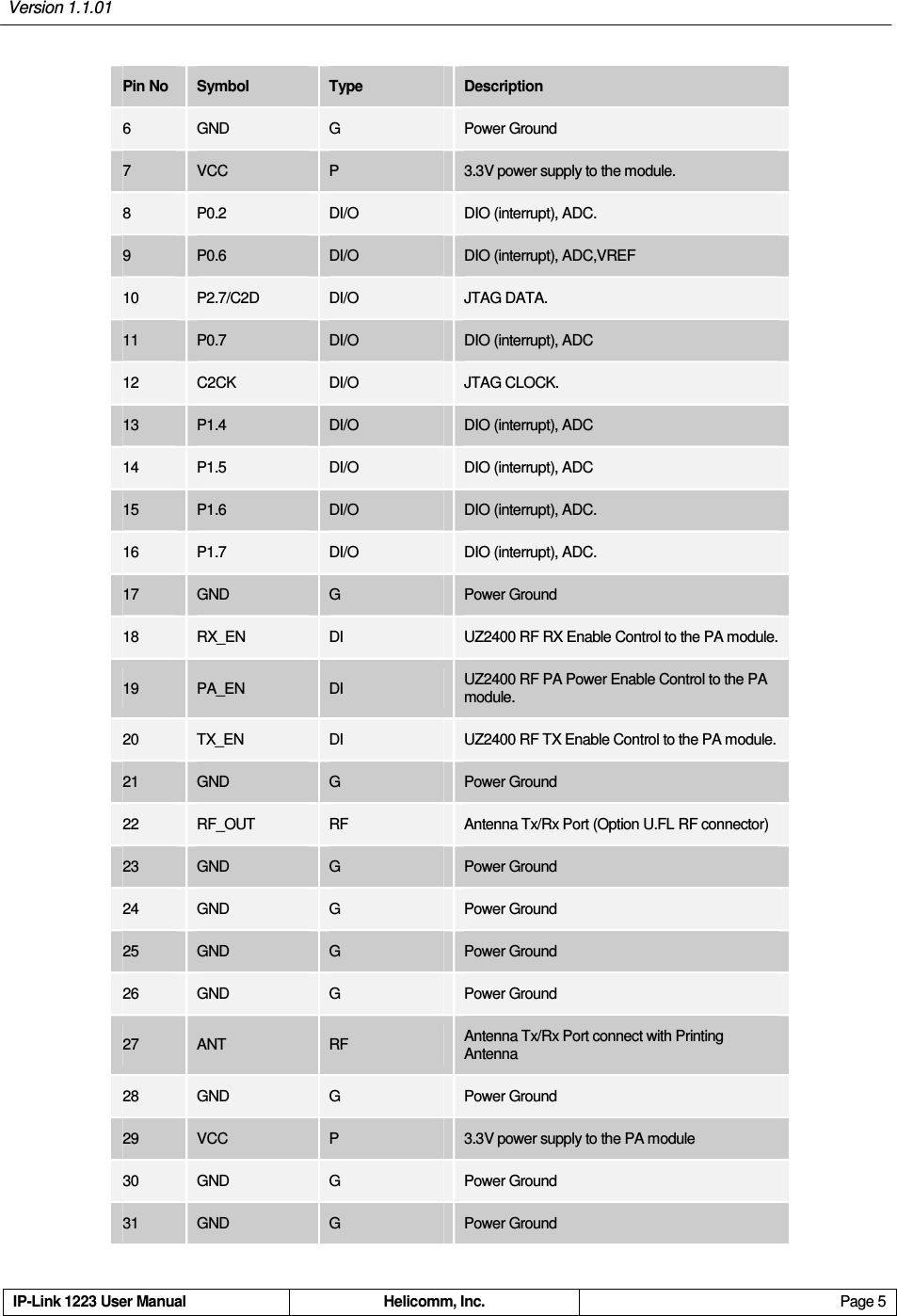
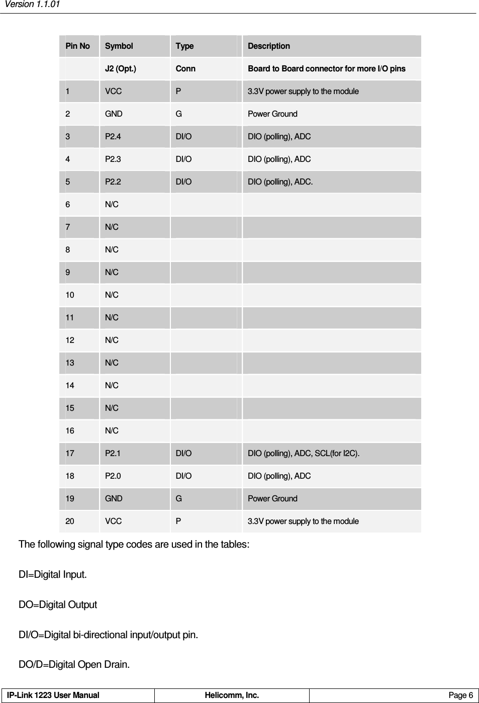
Helicomm IPLINK12235142 Embedded Wireless Module User Manual

Helicomm, Inc. Embedded Wireless Module

User manual

    IP•Link 1223 Embedded Wireless Module    User Manual   Version 1.1.02      Helicomm, Inc. www.helicomm.com
  Version 1.1.02 IP-Link 1223 User Manual  Helicomm, Inc.  Page i  © 2010 Helicomm, Inc.   All rights reserved. No part of this publication may be reproduced, adapted, or translated in any form or by any means without prior written authorization of Helicomm, Inc. Information published here is current or planned as of the date of publication of this document. Because we are improving and adding features to our products continuously, the information in this publication is subject to change without notice. Trademarks Helicomm, IPWINS, IP-Link, WIN-Gate, and IP-Net are trademarks of Helicomm, Inc.    ZigBee is a trademark of the ZigBee Alliance. All other product names mentioned in this publication are trademarks of their respective owners.    Revision and Iteration History Version  Publication Date  Authors  Summary of Changes and Updates 1.0.00  12/17/2008  Yr.Qie  Initial Draft 1.1.00  07/20/2009  Wt.Wu  Modify AT registers,the comment parameters about IO ports . And modify the formula for get IP-Link 1223 temperature. 1.1.01  07/09/2101  Frank Tung  Revised dimension 1.1.02  08/03/2010  Frank Tung  Added FCC information
  Version 1.1.02 IP-Link 1223 User Manual  Helicomm, Inc.  Page ii   FCC Information The equipment has been tested and found to comply with the limits for a Class B Digital Device, pursuant to part 15 of the FCC Rules. These limits are designed to provide reasonable protection against harmful interference in a residential installation. This equipment generates uses and can radiate radio frequency energy and, if not installed and used in accordance with the instruction, may cause harmful interference to radio communication. However, there is no grantee that interference will not occur in a particular installation. If this equipment dose causes harmful interference to radio or television reception, which can be determined by turning the equipment off and on, the user is encouraged to try to correct the interference by one or more of the following measures: --Reorient or relocate the receiving antenna. --Increase the separation between the equipment and receiver. --Connect the equipment into an outlet on a circuit different from that to which the      receiver is connected. --Consult the dealer or an experienced radio/TV technician for help.   This device complies with Part 15 of the FCC Rules. Operation is subject to the following two conditions: (1) this device may not cause harmful interference, and (2) this device must accept any interference received, including interference that may cause undesired operation.  The changes or modifications not expressly approved by the party responsible for compliance could void the user’s authority to operate the equipment.  To compl y with the RF exposure compl iance requirements, thi s device and its antenna must not be co-located or operating to conjunction with any other antenna or transmitter. This equipment should be installed and operated with minimum distance 20cm between the radiator & your body.   To OEM installer: 1. ID label on the final system must be labeled with "Contains FCC ID: RF2IPLINK12235142 / IC: 8576A-IPLINK5142" or "C ontain transmitter module FCC ID: RF2IPLINK12235142 / IC: 8576A-IPLINK5142 ".   2.In the user manual, final system integrator must be ensured that there is no instruction provided in the user manual to install or remove the transmitter module.   3. Transmitter module must be installed and used in strict accordance with the manufacturer is instructions as described in the user documentation that comes with the product. This device complies with the following radio frequency and safety standards.   The user manual of the final host system must contain the following statements:     This equipment has been tested and found to comply with the limits for a Class B Digital Device, pursuant to part 15 of the FCC Rules. These limits are designed to provide reasonable protection against harmful interference in a residential installation. This equipment generates, uses and can radiate radio frequency energy and, if not installed and used in accordance with the instruction, may cause harmful interference to radio communication. However, there is no grantee that interference will not occur in a particular installation. If this equipment dose causes harmful interference to radio or television reception, which can be determined by turning the equipment off and on, the user is encouraged to try to correct the interference by one or more of the following measures: --Reorient or relocate the receiving antenna. --Increase the separation between the equipment and receiver. FOR FCC AND INDUSTRY CANADA REQUIREMENT:“This device has been designed to operate with the antennas listed below, and having a maximum gain of[3] dB. Antennas not included in this list or having a gain greater than [3] dB are strictly prohibited for usewith this device. The required antenna impedance is [50] ohms.”“To reduce potential radio interference to other users, the antenna type and its gain should be so chosenthat the equivalent isotropically radiated power (e.i.r.p.) is not more than that permitted for successfulcommunication.”Operation is subject to the following two conditions: (1) this device may not cause interference, and (2) this device must accept any interference, including interference that may cause undesired operation of the device.
  Version 1.1.02 IP-Link 1223 User Manual  Helicomm, Inc.  Page iii  --Connect the equipment into an outlet on a circuit different from that to which the      receiver is connected. --Consult the dealer or an experienced radio/TV technician for help.   This device complies with Part 15 of the FCC Rules. Operation is subject to the following two conditions: (1) this device may not cause harmful interference, and (2) this device must accept any interference received, including interference that may cause undesired operation.   The changes or modifications not expressly approved by the party responsible for compliance could void the user’s authority to operate the equipment.   To compl y with the RF exposure compl iance requirements, thi s device and its antenna must not be co-located or operating to conjunction with any other antenna or transmitter.   This equipment should be installed and operated with minimum distance 20cm between the radiator & your body.  “This device has been designed to operate with the antennas listed below, and having a maximum gain of [3] dB. Antennas not included in this list or having a gain greater than [3] dB are strictly prohibited for use with this device. The required antenna impedance is [50] ohms.”  “To reduce potential radio interference to other users, the antenna type and its gain should be so chosen that the equivalent isotropically radiated power (e.i.r.p.) is not more than that permitted for successful communication.” Operation is subject to the following two conditions: (1) this device may not cause interference, and (2) this device must accept any interference, including interference that may cause undesired operation of the device.
  Version 1.1.02 IP-Link 1223 User Manual  Helicomm, Inc.  Page iv   Table of Contents1 Overview.......................................................................................................................... 1 2 Module Specifications ................................................................................................... 2 2.1 IP-Link 1223 Interface Pin Definitions.................................................................................. 4 2.2 Firmware Capabilities Specification..................................................................................... 8 3 Absolute Maximum Ratings .......................................................................................... 9 4 Operating Conditions................................................................................................... 10 5 Theory of Networking Operations .............................................................................. 11 5.1 Wireless Networking Topologies ....................................................................................... 11 5.1.1 Connectivity Topology versus Routing Topology....................................................... 11 5.1.2 Star Topology............................................................................................................. 12 5.1.3 Peer-to-peer (Mesh) Topology................................................................................... 13 5.2 Topology Selection ............................................................................................................ 14 6 Quick Steps in Establishing an IP-Link 1223 Network............................................. 15 6.1 Special Note: Establishing a Full Mesh Network ............................................................... 15 6.2 About the Mesh Topology Configuration of Module .......................................................... 15 7 IP-Link 1223 Command Set ......................................................................................... 17 7.1 AT Command Mode........................................................................................................... 17 7.1.1 AT Register Table ...................................................................................................... 18 7.1.2 AT Command Error Codes ........................................................................................ 23 7.2 Binary Mode....................................................................................................................... 23 7.2.1 Generic Frame Format............................................................................................... 24 7.2.1.1 Control Header Field ........................................................................................... 24 7.2.1.2 Link Quality Indicator ........................................................................................... 25 7.2.1.3 Destination Address Field.................................................................................... 25 7.2.1.4 Payload Length Field........................................................................................... 25 7.2.1.5 Payload Field....................................................................................................... 26 7.2.1.6 XOR Checksum Field .......................................................................................... 26 7.2.2 User Command Request Frame ................................................................................ 26 7.2.3 IP-Link 1223 Command Request Code Summary..................................................... 27 7.2.4 Helicomm Command Response Format.................................................................... 28 7.2.5 Helicomm Data Request Frame................................................................................. 29 7.2.6 Helicomm Acknowledgment Frame ........................................................................... 29 7.3 Helicomm Command Synopsis.......................................................................................... 29 7.4 Helicomm application mode synopsis................................................................................ 53 7.4.1 Tag mode application................................................................................................. 53 7.4.2 Local awakened sleep ............................................................................................... 53
  Version 1.1.02 IP-Link 122X User Manual  Helicomm, Inc.  Page v  7.4.2.1 Enter into sleep mode.......................................................................................... 53 7.4.2.2 Exit sleep mode ................................................................................................... 53 8 Some additive commands and settings of module.................................................. 54 8.1 The parity check of serial ports .......................................................................................... 54 8.2 The flow control of serial ports ........................................................................................... 54 8.3 Add loop back function in transparent mode ..................................................................... 54 9 Code of PC obtain the module’s firmware version information ............................. 55 10 Terminologies and Acronyms..................................................................................... 59 11 Mechanical Specification............................................................................................. 60 11.1 IP-Link 1223 Dimensions ................................................................................................... 60 11.2 IP-Link 1223 PAD .............................................................................................................. 61 11.3 Re-flow Temperature Specifications.................................................................................. 62 11.4 Solder Paste Recommendations ....................................................................................... 62 12 Ordering Information ................................................................................................... 63 13 Index............................................................................................................................... 64
Version 1.1.01     IP-Link 1223 User Manual  Helicomm, Inc.  Page 1   1  Overview IP-Link 1223 is Helicomm’s embeddable, Surface Mount Technology (SMT) IEEE 802.15.4/ZigBee-compliant wireless module.    IP-Link 1223 contains a powerful 8-bit 8051 microprocessor and a 2.4GHz IEEE 802.15.4-compliant RF transceiver. IP-Link 1223 can operate over 16 channels in the unlicensed 2.4GHz frequency band (or ISM, short for Industrial, Science and Medical) across the world. In addition to its IEEE-standard-based RF and PHY/MAC air interfaces, IP-Link 1223's embedded stack support a wide variety of useful networking features.    IP-Link 1223's network support is designed to cover a whole range of application needs, ranging from a simple beaconing network to complicated multi-story full ad hoc networks. Whether your applications need the robustness and simplicity of IEEE 802.15.4 standard or the versatility of ZigBee Compliance Platform, Helicomm's IP-Link 1223 is the vehicle to enable your applications to the power and cost advantages of standard-based short-range wireless networking.   IP-Link 1223 is ideal for a wide range of remote monitoring and control applications such as home control, meter reading, industrial automation, building automation, and security monitoring.   This manual contains vital information about Helicomm IP-Link 1223 embedded wireless transceiver modules.    It includes information on how the IP-Link 1223 can be easily provisioned, managed, and integrated into your existing products. Following is the structure of this manual.   Chapter 2 contains information on the IP-Link 1223 interface, performance and electrical specifications.       Chapter 3 gives the absolute maximum ratings to warn users using the device in the proper circumstance.   Chapter 4 specifies the IP-Link 1223 module’s operating conditions.   Chapter 5 offers a high-level description of the network operations supported by the IP-Link 1223, and how various network topologies can be configured to meet your application requirements.       Chapter 6 givers the special notes on setting up a full mesh network and how to do a mesh topology configuration of module.     Chapter 7 gives readers definitions and invocation mechanisms needed to develop their own host applications based on IP-Link 1223’s flexible networking capabilities.       Chapters 10 to 11 contain acronyms, mechanical dimensions, and manufacturing re-flow specification.
Version 1.1.01     IP-Link 1223 User Manual  Helicomm, Inc.  Page 2   2  Module Specifications MCU Clock Rate  24.5MHz FLASH ROM  64KB Micro-controller (MCU) RAM  4KB Frequency  2.4 GHz Receive Sensitivity  1223-50XX: -95 dBm 1223-51XX: -104 dBm Air Data Rate  250 Kbps Transmit Range  1223-50XX: 100 meters(LOS) 1223-51XX: 1200 meters(LOS) RF Channels  16 (5MHz) Transmit Power  1223-50XX: 0 dBm 1223-51XX: 22 dBm Data Encryption  CRC and AES-128 RF Antenna 1223-5X1X: Non. Ant. 1223-5X2X: PCB Ant. 1223-5X3X: Chip Ant. 1223-5X4X: U.FL Ext. Ant. Transmit/Receive  1223-50XX: 29mA/27mA 1223-51XX: 150mA/41mA Power Consumption  Sleep  1223-50XX: 4uA 1223-51XX: 60uA Physical Pins(Max.) 1223-5XX1: 31 1223-5XX2: 31 1223-5XX3: 51 Serial  One UART A-to-D(Max.) 9(10-bit ADC, two ADC in default status. It is used with IO together and the maximum is nine ADC. The more the number of ADC, the less the number of the available IO.) Comparators  Not support at present D-to-A  Not support Input/Output # of Programmable GPIO(Max.) 9(Seven  IO  in  default  status. It  is  used with  ADC  together  and  the  maximum  is nine IO. The more the number of IO, the less the number of the available ADC.) Connector Type 1223-5XX1: Stamp Hold 1223-5XX2: Pin Header 1223-5XX3: Pin Header+B2B(Full IO Pin Out) Physical Dimension (in inches)  1223-50XX: 0.79 x 0.87 x 0.07 1223-51XX: 2 x 1.6 x 0.59
Version 1.1.01     IP-Link 1223 User Manual  Helicomm, Inc.  Page 3   Dimension (in millimeters)  1223-50XX: 20 x 22 x 1.88 1223-51XX: 51 x 39.4 x 15 Operating Temperature  -20ºC to +70ºC Humidity (non-condensing)  10% to 90%
Version 1.1.01     IP-Link 1223 User Manual  Helicomm, Inc.  Page 4   2.1 IP-Link 1223 Interface Pin Definitions   Top View: (Red block is bottom side)  IP-Link 1223   Pin No  Symbol    Type    Description     J1  Hole  Stamp Hole and Through Hole 1  P0.0  DI/O  DIO (interrupt), ADC. 2  P0.1  DI/O  DIO (interrupt), ADC. 3  RX0  DI  Serial input of UART. 4  TX0  DO  Serial output of UART. 5  MCU_RESET  DI  MCU reset.
Version 1.1.01     IP-Link 1223 User Manual  Helicomm, Inc.  Page 5   Pin No  Symbol    Type    Description   6  GND  G  Power Ground 7  VCC  P  3.3V power supply to the module. 8  P0.2  DI/O  DIO (interrupt), ADC. 9  P0.6  DI/O  DIO (interrupt), ADC,VREF 10  P2.7/C2D  DI/O  JTAG DATA. 11  P0.7  DI/O  DIO (interrupt), ADC 12  C2CK  DI/O  JTAG CLOCK. 13  P1.4  DI/O  DIO (interrupt), ADC 14  P1.5  DI/O  DIO (interrupt), ADC 15  P1.6  DI/O  DIO (interrupt), ADC. 16  P1.7  DI/O  DIO (interrupt), ADC. 17  GND  G  Power Ground 18  RX_EN  DI  UZ2400 RF RX Enable Control to the PA module. 19  PA_EN  DI  UZ2400 RF PA Power Enable Control to the PA module. 20  TX_EN  DI  UZ2400 RF TX Enable Control to the PA module. 21  GND  G  Power Ground 22  RF_OUT  RF  Antenna Tx/Rx Port (Option U.FL RF connector) 23  GND  G    Power Ground 24  GND  G    Power Ground 25  GND  G    Power Ground 26  GND  G    Power Ground 27  ANT  RF  Antenna Tx/Rx Port connect with Printing Antenna 28  GND  G  Power Ground 29  VCC  P  3.3V power supply to the PA module 30  GND  G  Power Ground 31  GND  G  Power Ground
Version 1.1.01     IP-Link 1223 User Manual  Helicomm, Inc.  Page 6   Pin No  Symbol    Type    Description     J2 (Opt.)  Conn  Board to Board connector for more I/O pins 1  VCC  P  3.3V power supply to the module 2  GND  G    Power Ground 3  P2.4  DI/O  DIO (polling), ADC 4  P2.3  DI/O  DIO (polling), ADC 5  P2.2  DI/O  DIO (polling), ADC. 6  N/C     7  N/C     8  N/C     9  N/C     10  N/C     11  N/C     12  N/C     13  N/C     14  N/C     15  N/C     16  N/C     17  P2.1  DI/O  DIO (polling), ADC, SCL(for I2C). 18  P2.0  DI/O  DIO (polling), ADC 19  GND  G  Power Ground 20  VCC  P  3.3V power supply to the module The following signal type codes are used in the tables: DI=Digital Input. DO=Digital Output DI/O=Digital bi-directional input/output pin. DO/D=Digital Open Drain.
Version 1.1.01     IP-Link 1223 User Manual  Helicomm, Inc.  Page 7   AI=Analog input pin AO=Analog output pin RF=RF signal I/O pin P=Power pin G=Ground pin Note: IP-Link 1223-5142 is external antenna that must be connecting an extension low loss cable.   IP-Link 1223-5142 Module  Cable Antenna Housing  Cable length: 330mm  Cable Lose: 0.2 dB
Version 1.1.01     IP-Link 1223 User Manual  Helicomm, Inc.  Page 8   2.2 Firmware Capabilities Specification Baud Rate  38400(factory default) Configuration  8/N/1 Maximum Payload over Serial Port  97 Bytes Header Length  5 Checksum  1-byte XOR Serial Port Command Modes Supported AT Mode (off-line provisioning) Binary Command Mode Binary Data Mode Transparent: RS-232/485 emulation Maximum of Network Identifiers  65536 (0 ~ 65535) Range of Node Identifiers 0 ~ 65533 (0: Reserved for Network Master 65534: Reserved for self-loop back 65535: Reserved for broadcast) MAC Layer Blacklist  8 entries Routing Table  18-way Networking RREQ Table  4-way Sleep Mode  External Wakeup  RTC
Version 1.1.01     IP-Link 1223 User Manual  Helicomm, Inc.  Page 9   3  Absolute Maximum Ratings Parameter  Conditions Min  Type  Max  Units Voltage on any Pin    -0.3    3.6  V Maximum  Total  Current  through  VCC, AV+, GND, and AGND,RFGND        500  mA Maximum  Output  Current  Sunk  by  any Port pin        100  mA Maximum  Output  Current  Sunk  by  any other I/O pin        100  mA Maximum Output Current Sourced by any Port pin        100  mA Maximum Output Current Sourced by any other I/O        100  mA Storage Temperature    -40    +120  °C *Note:  The  absolute  maximum  ratings  given  above  should  under  no  circumstances  be  violated.  Stress exceeding one or more of the limiting values may cause permanent damage to the device.   Caution! ESD sensitive device. Precaution should be used when handling the device in order to prevent permanent damage.
Version 1.1.01     IP-Link 1223 User Manual  Helicomm, Inc.  Page 10   4  Operating Conditions Parameter  Conditions Min  Type  Max  Units Supply voltage  IP-Link 1223    2.7    3.6  V Operating ambient temperature range    -20    70  °C Humidity(non-condensing)    10%    90%
Version 1.1.01     IP-Link 1223 User Manual  Helicomm, Inc.  Page 11   5  Theory of Networking Operations IP-Link 1223 can be configured in a number of network topologies to meet different application needs.   It allows the users to design a network that best matches their installation conditions and applications’ needs. To design a network, it is empirical to understand how each individual IP-Link 1223 should be configured, and what each nodes individual capabilities as well as constrains are. In this Chapter we discuss the theory of networking operation of IP-Link 1223's networking capabilities to lay the groundwork for later chapters.    After reading this Chapter, users should have the system knowledge in assessing, configuring, deploying, and finally fine-tuning their IP-Link 1223 networks in real installations. 5.1 Wireless Networking Topologies In this section, we describe the key distinction between “connectivity” and “routing” topologies to establish the basic framework of wireless network design.    We then describe the working details, benefits, and constraints and recommended use case scenarios for the several routing options the IP-Link 1223 supports. This section provides a conceptual platform for readers before they use IP-Link 1223 to build wireless networks. 5.1.1  Connectivity Topology versus Routing Topology While the generic phrase network topologies suggests wires or cables connecting a host with communicating nodes, wireless communication modules like the IP-Link 1223 use a wireless broadcast medium to communicate. The IP-Link 1223 is a low-power transceiver module optimized for low-cost and low power consumption. So rather than transmitting at high power or having a huge antenna to improve receiver sensitivity, a single IP-Link 1223 transmits at relatively low power and utilizes message routing capability to cover a larger area if necessary in some applications. And because of the broadcast nature of wireless transmission, it is important to realize the differences between connectivity topology and messaging topology. Connectivity topology refers to the interconnect patterns at the Link level. In a wired network, topology refers to the physical wiring patterns among the nodes. Bus segments or point-to-point Links are some common connectivity topologies seen in Local Area Networks (LAN) or Wide Area Networks (WAN). In contrast, the connectivity pattern of a wireless network is usually visualized as overlapping radio circles or spheres, as illustrated here.    The RF sphere implies both range and channelization, which means that nodes with overlapping bubbles are directly connected with one another. So when considering a connectivity topology, the designer is usually concerned with design parameters such as overall coverage area, nodal density, and the transmission / reception characteristics of the transceiver modules.    The characteristics could accidentally change due to varying external conditions and variables such as trucks, walls, trees, and other RF emitters.
Version 1.1.01     IP-Link 1223 User Manual  Helicomm, Inc.  Page 12   On the other hand, a routing topology is a routing pattern over a multi-hop network. It describes an imaginary wiring diagram, weaving together all network nodes, allowing any arbitrary point to initiate a message (either unicast or multicast) to any fellow node in the network. A routing topology is constrained by the underlying connectivity topology.    But for some connectivity topology patterns in which multiple routing options are available (like most wireless networks), selecting the optimal routing topology for your network can be a challenge.    Two scenarios are presented here for demonstration.  Scenario 1: Linear Network   Let us examine a linear or “chain fence” scenario, in which any radio can only reach two immediate neighbors in opposite direction. In this extreme case, the choice of routing topology is constrained by the connectivity because there is only one deterministic way of getting a message from point A to point B in the whole network. This topology is common in pipeline monitoring applications and some traffic management and parking meter applications.  Scenario 2:    Fully Meshed Network In this scenario, we increase the size of the RF sphere and make some changes to the relative position. Now one can see that the new connectivity topology offers a wider array of routing options. In this particular diagram, each node will have two or more paths to reach a particular destination. In this case, the routing topology is no longer a simple choice. As illustrated in this scenario, routing topology decision for a low-power radio network involves the balance of many design objectives. The wireless network itself is a dynamic system, interacting with its environment incessantly.    People movement, intermittent use of electrical appliances, and outside interference sources are all affecting the bubble size. Further complicating the decision process is the design objective to conserve battery consumption for battery-operated devices. IP-Link 1223’s rich wireless routing algorithm is designed to simplify the decision process and expedite the deployment of a reliable, inexpensive wireless infrastructure. Its feature-rich and flexible networking capability aims to provide the network designers with sufficient alternatives and performance margin to easily come to a “just-right” routing topology to adapt to or even overcome the constraints imposed by underlying connectivity topologies. 5.1.2  Star Topology As its name suggests, a star routing topology is actually a hub-and-spoke system in which data traffic and network commands are routed through a central node, the Master.    In this routing topology, peripheral nodes require direct radio contact with the Master, and interference or the failure of a specific node can render the network less reliable, as each node provides a single point of failure.    Especially, the failure of the master node will result in complete system crash.    To construct a star network using IP-Link 1223, only one IP-Link 1223 module needs to be configured
Version 1.1.01     IP-Link 1223 User Manual  Helicomm, Inc.  Page 13   as a Master node. The remaining IP-Link 1223 modules can be programmed as an End node.   The most significant benefit of a star routing topology is its simplicity. The simplicity translates into very low-overhead protocol implementation, much lower overall device cost, very low-overhead routing information, and ease of administration. The central Master node can also assume many administrative roles such as certificate authority for authentication, or remote management gateway. However, the simplicity comes with a price of flexibility. Because of the requirement to put every single end node within the reach of the Master node, the overall network coverage is limited. And star topology networks cannot scale up easily to accommodate high-density deployment. The concentrated message routing towards the Master node can easily create a hot spot and lead to congestion, packet loss, and performance degradation, depending on the data traffic profile. The star topology is by far the most common architecture deployed today, and it is well suited for a variety of remote monitoring and control applications that do not need or cannot afford the cost and complexity overhead of a more sophisticated network topology. 5.1.3  Peer-to-peer (Mesh) Topology   Peer-to-peer, also known as mesh networking, is a free-form topology designed to be highly adaptive to the environment.    Each node in an IP-Link 1223 mesh network is a little router capable of re-assessing its routing decisions to provide the most robust, reliable network infrastructure possible. After configured as a mesh node, each IP-Link 1223 is capable of monitoring surrounding RF conditions, neighboring node activities, and end-to-end packet error rate statistics to adjust its local routing decisions on the fly. Such adaptability is extremely valuable to network designs that are facing uncertain or unpredictable Link conditions.   Mesh topology uses both the RF broadcast nature as well as a set of route inquiry and maintenance commands to dynamically update the distributed routing information across the entire network.    The mesh protocol supported by IP-Link 1223 is similar to Ad hoc On-Demand Vector (AODV) routing, in which the node originating a message is responsible for establishing a suitable route by querying its immediate neighbors. The route queries process gradually ripples through the network until the destination confirms connectivity and initiates a reply.    Such reply now ripples backwards toward the originator, accumulating vital routing statistics along its way. Finally, the originating node receives the most up-to-date route information and makes a routing decision based on that information. The newly computed routing information will age within a certain window and mandate new route computation after it expires to ensure route decision is based on fresh information. Mesh is ideal for highly unstructured network deployment. When the deployment premise is open and potential interference sources or barriers are anticipated, mesh topology is a reliable way of ensuring wireless connectivity. Especially when deployment density is medium or high, the added redundancy by mesh topologies can add significant design margin and flexibility into the overall networks. Given its more sophisticated capabilities, however, characterizing and validating a mesh network is more difficult and complicated compared to star or cluster tree networks.    Unlike star or cluster tree, a mesh network dynamically adjusts the routing topologies and does not exhibit a fixed, predictable routing pattern. This makes the messaging latency highly dependent on the instantaneous Link quality and difficult to predict. More importantly, a qualitative comparison of mesh algorithms is always a challenging task even for the most savvy network designer.
Version 1.1.01     IP-Link 1223 User Manual  Helicomm, Inc.  Page 14   Network designers usually deploy mesh for applications that require a highly reliable, highly available wireless infrastructure. Mesh networks should also be considered as a means to reduce initial network setup cost and post-installation maintenance needs by leveraging the self-configuring capabilities embedded inside IP-Link 1223 modules. 5.2 Topology Selection IP-Link 1223’s rich wireless routing algorithm is designed to simplify the decision process and expedite the deployment of a reliable, inexpensive wireless infrastructure. Its feature-rich and flexible networking capability aims to provide the network designers with sufficient alternatives and performance margin to easily come to a “just-right” routing topology to adapt to or even overcome the constraints imposed by underlying connectivity topologies. Deciding the routing topology of your applications can be very easy with IP-Link 1223. The decision usually needs answers for the following series of questions: 1.  Worst-case and average-case connectivity topologies:    What type of installation density do your applications call for (e.g., what is the longest and average distance between your devices), and what is the surrounding environment’s conditions in terms of RF interference, building structure and moving objects? 2.  Evaluate routing alternatives: select from one of the topologies discussed in this chapter. Based on the information from (1), select a core routing topology that meets your design objectives. 3.  Fine-tune routing alternatives by selectively upgrading potential weak spots and balancing against power/resource design constraints.
Version 1.1.01     IP-Link 1223 User Manual  Helicomm, Inc.  Page 15   6  Quick Steps in Establishing an IP-Link 1223 Network In this chapter we provide some special notes on forming an IP-Link 1223 network The establishment of Mesh network please re. 6.1 and 6.2 .   6.1 Special Note: Establishing a Full Mesh Network A full ad hoc mesh network is appealing to many users because of its ease of configuration.    In this configuration, all nodes are viewed as equals, and each of them will be a “trustworthy” neighbor to any other nodes within its radio contact.    And many users prefer to deploy a full mesh network without going through the sequential process of joining each and every device into the network.    Rather than assigning Network Layer address one at a time via Master Node, some users choose to pre-configure address information.    Pre-configure address assignment works particularly well for full mesh network, since run-time path is established dynamically rather than relying on static parent-child relationship. 1.  It is quite straight-forward to configure your IP-Link 1223 devices into a full-mesh-capable device.    You should prepare to setup every node with the following common configurations:   An identical RF Channel   An identical MAC Layer Network Identifier (from 0 to 65535) Note: the particular configure information please re. 6.2 2.  Now provision a unique MAC Node Identifier into each module.    The unique Node Identifier can be selected from the range of 0 to 65533. Note that Node 0 in a full mesh network does not have any supremacy over other nodes any more.    A full mesh network can operate even without Node 0.   3.  Turning on devices: For a full mesh network, devices can be turned on at any arbitrary order. 4.  Validating connection: It is strongly recommended that you “walk” the entire network from any node that has an external connection that accepts Helicomm's Binary Mode Command Set.   For example, you can hook up a Personal Computer to any node and start querying the entire crew in the network.    You can run such a “scan” continuously over an extended period to develop some ideas on your deployment environment as well as the network's stability. 6.2 About the Mesh Topology Configuration of Module Introduce how to use binary command to configure mesh topology. About the binary command, please reference to 7.2 Binary Mode. The method is to set some related Registers, command code is 0x87 The registers need to be set are: 0X70: send power, range from 0 to 7, 0 is the max
Version 1.1.01     IP-Link 1223 User Manual  Helicomm, Inc.  Page 16   0X72: channel, 0~15, 0X96: node type, master is 0, client is 1 0X99: set to 1 0X9A: set to 1 0X9E: 0 0X9F: 0xFF 0XA0: 0x00 0XB4: 0x01 0XB5: 0x01 0XB7: 0x00 0XBC: high bits of net node ID 0XBD: low bits of net node ID 0XBE: high bits of net ID 0XBF: low bits of net ID 0XC0: high bits of mac node ID, the same as 0xBC 0XC1: low bits of mac node ID, the same as 0xBD  For example, send command code: 81 00 FF FE 03 87 70 00 74, the function of this command is setting power to 0. Return: C1 00 00 01 02 87 00 45
Version 1.1.01     IP-Link 1223 User Manual  Helicomm, Inc.  Page 17   7  IP-Link 1223 Command Set Helicomm IP-Link supports two categories of external command sets. One is the familiar AT command set that is similar to those supported by Hayes-compatible modems. The second category of commands consists of binary instructions that enable a host processor to use IP-Link 1223 as a wireless network interface. Application developers usually use AT command set to query and set attributes on a standalone module. After the configuration completes, application software can then invoke a binary command set to issue commands and exchange data packets across the wireless network. On the bases of these two command setting categories, IP-Link1223 supports two modes when it communicates to the outside applications: AT Mode and Binary Mode. When IP-Link 1223 powers up, it defaults to the binary mode. User issues special escape sequence to switch into AT Mode, and another special AT command to switch back into data mode. This chapter is organized as follows:     •  Section 7.1 presents the AT command set and detailed definitions on IP-Link 1223’s S Register definitions.     •  Section 7.2.1 introduces the structure of IP-Link 1223’s generic frame format and field definitions.   •  Sections 7.2.2 through 7.2.6 give detailed descriptions of the four types of command frames supported by IP-Link 1223.     •  Section 7.3 provides detailed information on every command request and its corresponding responses. 7.1 AT Command Mode IP-Link 1223 provides a host of AT commands to allow easy configuration of key attributes of an IP-Link 1223 module. The following texts describe the AT commands, their parameters, and the responses.    You can use any terminal emulation utility or UART communication library on a particular host platform to issue these AT commands to IP-Link 1223.   AT String  Purpose  Parameter  Return String +++  Escape sequence into AT Mode  N/A Successful: no return value; returns O when a second “+++” is issued Error: Exxx - - -N-  Escape sequence into transparent Mode N = 0 ~ 65533,   65535, in decimal  N/A ===  Switch to Binary Mode  N/A  N/A
Version 1.1.01     IP-Link 1223 User Manual  Helicomm, Inc.  Page 18   AT String  Purpose  Parameter  Return String AT#n\r  Set MAC Layer Network Identifier  n = 0 ~ 65535  Successful: O Error: Exxx AT@n\r  Set MAC Layer Node Identifier  n = 0 ~ 65534  Successful: O Error: Exxx ATSxxx?\r  Query Register Value  xxx: S register index (in decimal) Successful: ATSxxx=xxx Error: Exxx ATSxxx=yyy\r  Set Register Value xxx: register index (in decimal) yyy: register value (in decimal) Successful: O Error: Exxx AT/$\r  Get IEEE MAC Address  N/A  LongMac=0xhhhhhhhhhhhhhhhh AT/B\r  Get module firmware built timestamp  N/A  Month dd yyyy hh:mm:ss AT/#\r  Get MAC Layer Network Identifier  N/A  MacPanID=n AT/@\r  Get MAC Layer Node Identifier  N/A  ShortMacAddress=n AT/S\r  Query All Register Values N/A  S100=aaa S101=bbb S102=8 … S230=x AT/V\r  Query Module Firmware Release Number N/A  a.b.c ATW\r  Write Back Settings  N/A  Successful: O Error: Exxx ATR\r  Restore Default Settings  N/A  Successful: O Error: Exxx  7.1.1  AT Register Table In this section we present a table of IP-Link 1223 S Registers and valid range for each register location. These register entries can be read and set through the commands described in the previous section. The exact Register indexes and acceptable input values are summarized in the table below. For maintenance reasons, some of these S Registers should not be modified and are only displayed for informational purpose. These entries are labeled as “Reserved” under the field “Access Type.”   Readers are strongly advised NOT to modify these S Register settings, or Helicomm cannot guarantee the firmware’s performance.
Version 1.1.01     IP-Link 1223 User Manual  Helicomm, Inc.  Page 19   Register Name  S Register Index (decimal) Access Type Purpose  Range (decimal) Manufacturer Default (decimal) UART Baud Rate  101  R/W  UART Baud Rate  0:115200 bps 1: 57600 bps 2: 38400 bps 3: 19200 bps   4: 9600 bps 5:4800 bps 6:2400 bps 7:1200 bps 8:28800 bps 9:600 bps 2 UART Data Bit  102  R/W  Number of data bits 8:8 bit 9:9 bit 8 UART Parity  103  R/W  Parity bit  0:none 1:odd 2:even 3:mark 4:space 0 UART Timeout  104  R/W  Timeout value, in milliseconds, for UART N/A  8 UART Buffer Size  105  Reserved  UART Buffer size in bytes   128 UART Flow control  106  R/W  UART Flow control  0:FALSE 1:TRUE 0 RF Baud Rate  111  R  RF Baud Rate  0: 250 Kbps  0 RF Send Power  112  R/W  RF Send Power select Register 0: 0 dBm         1: -1 dBm        2: -3 dBm        3: -5 dBm        4: -7 dBm        5: -10 dBm        6: -15 dBm        7: -25 dBm 0 RF Accept and Send buffer size 113  Reserved  RF Accept and Send buffer size   116 RF Channel  114  R/W  RF Channel Select Register 0 ~ 15             0: 2.405 GHz 4
Version 1.1.01     IP-Link 1223 User Manual  Helicomm, Inc.  Page 20   Register Name  S Register Index (decimal) Access Type Purpose  Range (decimal) Manufacturer Default (decimal) 1: 2.410 GHz ...                     14: 2.475 GHz 15: 2.480 GHz RF Frequency  115  R  RF Frequency  3: 2.4 GHz  3 Wait ACK TimeOut  141  R/W  Timeout, in 10 milliseconds 0 ~ 255  50 Retry Send Rreq For Myself 142  R/W  Number of retry times 0 ~ 255  1 Retry Send Mac Packet 143  R/W  Number of retry times 0 ~ 255  1 Wait Rrep TimeOut  144  R/W  Timeout, in milliseconds 0 ~ 255  100 Retry Send Rreq For Others 145  R/W  Number of retry times 0 ~ 255  1 Repeat MultiBroadCast  147  R/W  Number of repeat times 0 ~ 255  1 Node Type  150  R/W  Node Type Select Register 0: Master 1: RN+ 2: RN- 3: RFD 255: Unassigned 0 Routing Algorithm  158  R/W    0: AODV 1: Cluster Tree 2: CT/AODV 0 Table Expiration Value  159  Reserved  Expiration time, in seconds   255 Topology Type  160  R/W    0 ~ 255  97 Aodv TTL Value  163  R/W    0 ~ 255  100 Network State  170  R/W    0: Unassigned 1: JOIN NETWORK     0
Version 1.1.01     IP-Link 1223 User Manual  Helicomm, Inc.  Page 21   Register Name  S Register Index (decimal) Access Type Purpose  Range (decimal) Manufacturer Default (decimal) 2: LEAVE NETWORK     3: REPORT ACCEPT CHILD   4: REPORT LOST CHILD Work Mode  173  R/W    0: HELICOMM FRAME MODE 1: AT COMMAND MODE 2: TRANSPA RENT MODE 0 Transparent Mode destination, Upper Byte  174  R/W    0 ~ 255  255 Transparent Mode Destination,    Low Byte 175  R/W    0 ~ 255  255 Transparent Mode LoopBack Flag 176  R/W    0: FALSE 1: TRUE 0 MAC Layer Ack Flag  180  R/W    0: FALSE 1: TRUE 1 NET Layer Ack Flag  181  R/W    0:FALSE 1:TRUE 1 Time Control  183  R/W  Control the time space of Net Link Checking, in seconds 0 ~ 255  0 Digital Input sleep gap  184  R/W  Refer to Digital Input Commands definition 0 ~ 20, in 100ms 0: Disable this function 0 Digital Input monitor’s Node ID, Upper Byte 185  R/W    0 ~ 255  0 Digital Input monitor’s Node ID, Lower Byte 186  R/W    0 ~ 255  0
Version 1.1.01     IP-Link 1223 User Manual  Helicomm, Inc.  Page 22   Register Name  S Register Index (decimal) Access Type Purpose  Range (decimal) Manufacturer Default (decimal) Network Layer Node ID, Upper Byte 188  R/W    0 ~ 255  0 Network Layer Node ID, Lower Byte 189  R/W    0 ~ 255  0 MAC Layer PAN ID, Upper Byte 190  R/W    0 ~ 255  0 MAC Layer PAN ID, Lower    Byte 191  R/W    0 ~ 255  0 MAC Layer Node ID, Upper Byte 192  R/W    0 ~ 255  0 MAC Layer Node ID, Lower Byte 193  R/W    0 ~ 255  0 MAC Layer Beacon Mode(reserved for future use) 194  R/W    0 ~ 255  0 MAC Layer Node Type(reserved for future use) 195  R/W    0 ~ 255  0 Security Mode(reserved for future use) 196  R/W    0 ~ 255  255 AppLocalizer Time 230  R/W  Control the time space of Tag request, in 0.1seconds 0 ~ 255 0: Disable this function 0 LED Flag  231  R/W  Set the ports used by LEDs free when this flag is FALSE, then they can be used as GPIOs 0: FALSE 1: TRUE 1 Remote Flash Flag  232  R/W  Allow writing remote flash or not 0: FALSE 1: TRUE 0 Sleep mode flag  233  R/W  Entry sleep mode  0:FALSE, 1:TRUE 0 Sleep base time  234  R/W  Sleep base time  1~40  2
Version 1.1.01     IP-Link 1223 User Manual  Helicomm, Inc.  Page 23   Register Name  S Register Index (decimal) Access Type Purpose  Range (decimal) Manufacturer Default (decimal) Uart Tag  236  R/W  Entry Uart Tag mode or choose the tag table type 0~4  0 Set ADC Vref  242  R/W  Set ADC Vref  0~2  0 I/O Function  244  R/W  Set IO Function  0~255  0 I/O default State  245  R/W  Set IO default State 0~255  255 Disable Bootloader  246  R/W  Disable or enable bootloader 0:enable 1:disable 0  7.1.2  AT Command Error Codes When AT commands execute successfully, IP-Link 1223 firmware returns a related marker (see the AT Commands Table in Page 16) as a success indication.    In the case of execution failure, IP-Link 1223 firmware returns one of the following three error codes to indicate the condition. Error Code  Error Diagnosis 100  Invalid Command 101  Invalid Register 102  Invalid Value 7.2 Binary Mode In Binary Mode, host applications use binary-formatted command and responses to command the local modules as well as communicate to remote nodes across the network. This highlights the key utility of Binary Mode operations compared to AT Mode: to communicate and command remote modules over the network formed by multiple IP-Link modules. That said, there are still shortcut commands in Binary Mode to allow users to quickly perform local module access without forcing the application to go through mode switches. In the simplest terms, Binary Mode and AT Mode have overlapping functionalities and are designed to complement each other. IP-Link 1223 supports four types of frames in its Binary Mode.    Command Request, Command Response, Data Request, and Acknowledgment.   To use IP-Link 1223’s Binary Mode, a Host Application starts with building Command Request Frames to query, configure, and command a remote IP-Link 1223 for networking-related functions.   The remote IP-Link 1223 module will automatically return a Command Response Frame to notify the execution result to the command-issuing module. The sending application then parses the Command
Version 1.1.01     IP-Link 1223 User Manual  Helicomm, Inc.  Page 24   Response Frame to take further actions. Some configuration records and sensor information natively supported by IP-Link1223 can also be retrieved using Command Request and Command Response. These commands are built-in to IP-Link 1223, and these Commands cannot be extended or modified by the users. On the other hand, host applications use Data Request and Acknowledgement Frames to exchange user-specific data.    IP-Link 1223’s transport the data frames in an end-to-end fashion without interpreting or manipulating the payload in a Data Request Frame. The destination IP-Link 1223 will automatically generate an Acknowledgement Frame to report the reception status of the Data Request Frame.    After the network topology is established, Data Request Frame is the main interface that application developers can use to exchange information among multiple IP-Link 1223 modules. These frames can also be used to carry user-defined network-wide commands, such that IP-Link 1223 can be extended to support any custom commands users desire. All these frames can be exchanged from one IP-Link 1223 module to a peer module within the same network. The routing of these frames over any given topology is handled by IP-Link 1223’s embedded firmware transparently. 7.2.1  Generic Frame Format All four types of frames – Command Request, Command Response, Data Request, and Acknowledgment – use the same generic frame structure: five (5) bytes of packet header descriptor, 0 to 97 bytes of frame payload, and one (1) byte of XOR checksum at the end of packet.     All IP-Link 1223 binary frames follow the following variable-length frame structure: Control Header (1) Link Quality   Indicator (1) Destination   Address (2) Payload Length (1) Payload (0 –    97) XOR Checksum (1)  Following is the detailed description of the common packet header descriptor. 7.2.1.1    Control Header Field Length: one byte  Bit Field Definition:   Bit 7,6,5:  Binary Frame Type:  100  command request 110  command response 101  data request 111  data acknowledgement  Bit 4:     Reserved for future use.    Default to 0.
Version 1.1.01     IP-Link 1223 User Manual  Helicomm, Inc.  Page 25    Bit 3,2,1,0:  Packet Sequence Number, modulo 16.      NOTE: This sequence number is specifically designed for user applications, the nearby packets must have different sequence numbers, for example, the sequence numbers change circularly from 0 to 15     IP-Link 1223's firmware maintains separate sequence numbers for data packets.    They are transparent to Binary Mode users. 7.2.1.2    Link Quality Indicator Length: one byte Bit Field Definition: Bit 7 ~ 0:    A 8-bit hex value representing the incoming packet's Link Quality Description: The Link Quality Indicator (LQI) is an estimate on the packet's signal integrity.    Its value ranges from 0 to 255.    The higher the value, the better the signal quality.    This estimate is derived from IEEE 802.15.4 PHY layer processing performed by any compliant IEEE 802.15.4 transceiver.   Users can use this information to assess the MAC-Link quality of a node's surrounding devices.    This estimate can be used in conjunction with RSSI. 7.2.1.3    Destination Address Field Length: two bytes Bit Field Definition:  Bit 15 ~ 0: Destination Node’s Network Address  Description: 0x0000, 0xFFFE, and 0xFFFF are all reserved address -- 0x0000 for Network Master, 0xFFFE for loopback (to the sender itself), and 0xFFFF for broadcast. 7.2.1.4  Payload Length Field Length: one byte  Bit Field Definition:   Bit 7~0: Represents the payload length (excluding the 5-byte header and 1-byte XOR checksum) in hexadecimal.      Description: Its valid range should be from 0x00 to 0x61 (decimal 97).
Version 1.1.01     IP-Link 1223 User Manual  Helicomm, Inc.  Page 26   7.2.1.5    Payload Field Length: variable length from 0 to 97 bytes Bit Definition: User defined. Description: The magic number 97 is due to the limitation from IEEE 802.15.4 MAC Layer's maximum payload size. 7.2.1.6    XOR Checksum Field Length: one byte  Bit Definition: Bit 7~0: XOR Checksum Description: The XOR checksum is calculated by perform a byte-wide XOR sum on the entire packet header and payload.    If an XOR checksum fails, the frame will be discarded automatically. 7.2.2  User Command Request Frame In Command Request Frame, an additional byte is used to denote a Command Code identifier.   Helicomm provides a set of built-in command/responses to allow users to manage and retrieval information regarding the networks as well as the sensor information provided by Helicomm’s hardware solution.    Each command code identifier will possess its own syntax for both request and response.  Control Header (1) Command Request  (4-bit) b1000 Sequence Number  (4-bit) Link Quality Indicator (1) Destination Address (2) Payload Length   (1) Command Code (1) Parameters (0 – 96) XOR Checksum (1) When composing a Command Request Frame, user applications should supply the following information: •  A four-bit, user-defined packet sequence number: this number will be echoed back in receiver’s Command Response Frame.   •  Destination node’s network address: Combined with the Packet Sequence Number, users can use these two numbers to uniquely match an incoming Response to a pending Command.
Version 1.1.01     IP-Link 1223 User Manual  Helicomm, Inc.  Page 27   •  The total payload length (up to 0x60) •  The command code: refer to the table in this section. •  The Command parameter: refer to Command Synopsis •  And the XOR checksum on all the bytes preceding the last When sending a Command Request Frame, user applications should be ready to manage three possibilities: 1. First, the request completes successfully with the expected Response. In this case, the Command Response Frame will be available in the receiving buffer, and host applications can read the serial port input buffer to gather the Response frame. 2. The second condition is that a remote node returns an error indication. In this case, the end-to-end communication is working properly, but the command request is not accepted. Check command syntax and values to correct such problems. 3. The third condition is potentially a communication failure or invalid local command.    For communication failure, users may experience continuing checksum error or timeout.    In this case, check your communication quality and environment (e.g., moving the destination node closer to the transmitter, or switch to a simpler network topology.)    For an invalid local command, verify that you are using the correct network address to address the local module, and the command is formatted correctly. 7.2.3  IP-Link 1223 Command Request Code Summary Following is a summary of the Command Request set currently supported by IP-Link 1223, firmware release v7.0.00 and v7.0.01.    Please refer to Command Request Frame Synopsis in Section 7.3, for complete, individual command’s information.1 Command Category  Command Name  Command Code (hex) Get IP-Link 1223 ADC Sample  0x81 Get IP-Link 1223 RSSI Sample  0x82 Sample and ADC Get IP-Link 1223 Temperature  0x83 Get AT Mode S Register Setting  0x86 Module Settings Set AT Mode S Register Setting  0x87 Module MAC Settings  Get MAC Address  0x8B Get Firmware Version Number  0x8C Get Module Type  0xC3 Power Management Entry Power Down Mode  0x8D                                                       1  The command set can be subject to change without notice.  Please refer to Helicomm’s website for the latest documentation and firmware release.
Version 1.1.01     IP-Link 1223 User Manual  Helicomm, Inc.  Page 28   Command Category  Command Name  Command Code (hex) Soft Reset Module  0x8F Hardware Reset Module  0XC0 Enter sleep mode re. Local awakened sleep 0xB1 Reset to Factory Default  0x90 Get Routing Table  0x95 Get Black List Table  0x9C Set Black List Table  0x9D TRACERT  0xAA TRACERT with RSSI  0xBB Scan Neighbor  0xBC Get IO  0xAC Module Network Settings Set IO  0xAD 7.2.4  Helicomm Command Response Format Control Header (1) Command Response  (4-bit) b1100 Sequence Number  (4-bit) Link Quality Indicator (1) Destination Address (2) Payload Length   (1) Command Code (1) Response (0 – 96) XOR Checksum (1)  Command Response Frame is used to indicate back to the originator the execution results of a Command Request Frame.     If the command executes correctly, first the Command Code field in the Response Frame will echo the original command code. Further, a destination node will return any result in the RESPONSE field. If there is no result to return to the sender a value of 0x00 will be placed in the RESPONSE field If the command execution fails, the destination node will place a 0xFF into the Command Code field.   Further the very first byte in Response field will contain an error code for diagnosis purpose.    The following table is a summary of possible error codes.    Error Code  Value (hex)  Comments ERROR_XOR_ERROR  0x01  Checksum error ERROR_SEND_FAIL  0x02  Send failure ERROR_COMMAND  0x03  Invalid Command
Version 1.1.01     IP-Link 1223 User Manual  Helicomm, Inc.  Page 29   Error Code  Value (hex)  Comments ERROR_CMD_PARAM  0x06  Invalid Command Parameter ERROR_DEST_ERROR  0x07  Invalid Destination Address ERROR_NET_BUSY  0x09  Network Busy 7.2.5  Helicomm Data Request Frame Control Header (1) Data Request  (4-bit) b1010 Sequence Number  (4-bit) Link Quality Indicator (1) Destination Address (2) Payload Length   (1) Data Payload (0 – 97) XOR Checksum (1)  In this Data Request Frame, applications can deposit the application-specific data (of up to 97 bytes) into the Data Payload and transmit it to the target receiver. The receivers are expected to return an Acknowledgment Frame. 7.2.6  Helicomm Acknowledgment Frame Control Header (1) Data     ACK   (4-bit) b1110 Sequence Number  (4-bit) Link Quality Indicator (1) Destination Address (2) Payload Length   (1) Error Code (1) Error Type (1) XOR Checksum (1)  If a Data Request Frame is received successfully, the receiver will return a Data Acknowledgement Frame, back to the originator, with 0x00 for both Error Code and Error Type fields.    For error conditions, Error Code will be set to 0xFF and error type will contain one of the diagnostic error code shown in the table below. Error Type  Value (hex) Comments ERROR_XOR_ERROR  0x01  Checksum Error ERROR_SEND_FAIL  0x02  Transmission Failed ERROR_DEST_ERROR 0x07  Invalid Destination Address ERROR_NET_BUSY  0x09  Network Busy 7.3 Helicomm Command Synopsis
Version 1.1.01     IP-Link 1223 User Manual  Helicomm, Inc.  Page 30   The following sections describe in detail the current command set available on IP-Link 1223.    Users can refer to this information to build the command library for their particular host application platforms.
Version 1.1.01     IP-Link 1223 User Manual  Helicomm, Inc.  Page 31   Get IP-Link 1223 ADC0 Sample Read the sample from IP-Link 1223’s ADC0 Command Code 0x81 Description This command is used to retrieve the sample from IP-Link 1223’s built-in analog-to-digital converter.    IP-Link 1223 has a two 10-bit ADCs at ADC#1 and ADC#0 are available on IP-Link 1223’s Pin #15(P1.6) and Pin #16(P1.7), respectively, to connect to user’s analog signal source.   When returned successfully, the first and second byte should be concatenated together to get the 10-bit ADC sample.   S242=0 (1.68V input against core): The input signal voltage to ADC shall be in the range of 0~3.36VDC. Upon the READ_ADC command, firmware will add up 16 continuous samples, divide the sum by 16, and report the adjusted 10-bit sample. S242=1 (external): The reference voltage will be taken from IP-Link 1223's PIN# 9. Upon the READ_ADC command, firmware will add up 16 continuous samples, divide the sum by 16, and report the average 10-bit sample.   NOTE: user shall make sure that hardware reference design matches the S242 configuration, or the ADC samples might become unpredictable. S242=2 (1.68V input against core): The input signal voltage to ADC shall be in the range of 0~1.68VDC. Upon the READ_ADC command, firmware will add up 16 continuous samples, divide the sum by 16, and report the adjusted 10-bit sample. Command Parameters ADC Channel                          1 Byte                        0x00: enable ADC#0                                                                                       0x01: enable ADC#1 Response ADC High Byte                        1 Byte    the most significant 2 bits of the sample                                                   (right-aligned) ADC Low Byte                        1 Byte    the 8 least significant bits of the sample
Version 1.1.01     IP-Link 1223 User Manual  Helicomm, Inc.  Page 32   Get IP-Link 1223 RSSI Reading Read IP-Link 1223 RSSI reading Command Code 0x82 Description This command retrieves the RSSI value, in dBm, from IPLink 1223.    The dBm is a signed value.    For instance, a reading of “B0” (hex) represents an RSSI value of-80dBm. Command Parameters N/A Response RSSI                                  1 Byte  RSSI value in hexadecimal, a signed value
Version 1.1.01     IP-Link 1223 User Manual  Helicomm, Inc.  Page 33   Get IP-Link 1223 Temperature Read the temperature sample from a remote IP-Link 1223 Command Code 0x83 Description Issue this command to retrieve the ambient temperature sensed by IPLink 1223.    To derive at the actual temperature reading, the following conversion should be applied on the 10-bit sample S: For IP-Link 1223: Celcius: 25 +(( S *3.3/1023) -1.025 )/0.0034 Command Parameters N/A Response Temperature High Byte      1 Byte              the most significant 2 bits of the sample   (right-aligned) Temperature Low Byte        1 Byte      the least significant 8 bits of the sample
Version 1.1.01     IP-Link 1223 User Manual  Helicomm, Inc.  Page 34   Get AT Mode S Register Setting Get a particular S Register’s value under AT Mode Command Code 0x86 Description This is a shortcut for getting an S Register’s value under AT Mode.    It is equivalent to issuing ATSxxx? under AT Mode.    The difference is that now this capability now can be used across the network. Command Parameters S Register Location      1 Byte            S Register index in hexadecimal Response S Register Value      1 Byte            Value in the requested S Register in hexidecimal
Version 1.1.01     IP-Link 1223 User Manual  Helicomm, Inc.  Page 35   Set AT Mode S Register Setting Set a particular S Register’s under AT Mode   Command Code 0x87 Description This command can be used to set a remote or local module’s S Register. Users are advised to use this command with caution. Improper use of this command can result in modules unable to communicate to the rest of the network. Note: This command can only be used to set the local module in default state. For the remote module,you should   have the module enable remote configuring the Register if needed. Command Parameters S Reigster Location            1 Byte    S Register index in hexadecimal S Register Value                1 Byte    Value for the S Register in hexidecimal Response   Command Confirmation                         1 Byte    0x00 (constant)
Version 1.1.01     IP-Link 1223 User Manual  Helicomm, Inc.  Page 36   Get MAC Address Get MAC layer hardware address Command Code 0x8B Description This command retrieves an IP-Link 1223 module’s IEEE 64-bit MAC hardware address. Command Parameters N/A Response MAC Address                        8 Byte              64-bit IEEE MAC address, MSB first
Version 1.1.01     IP-Link 1223 User Manual  Helicomm, Inc.  Page 37   Get Firmware Version Number Get release number of IP-Link 1223 module firmware Command Code 0x8C Description This command retrieves the firmware release number on the destination IP-Link 1223 module. Command Parameters N/A Response Major                          1 Byte  Major release number, in hex Minor                          1 Byte  Minor release number, in hex Revision            1 Byte  Revision number, in hex
Version 1.1.01     IP-Link 1223 User Manual  Helicomm, Inc.  Page 38   Entry Power Down Mode Power down IP-Link 1223 module Command Code 0x8D Description This command powers down the remote IP-Link 1223 module. The target module will return a Command Response frame and shuts down. Once the module has entered this mode, it can only be waken by hardware reset. Command Parameters N/A Response Command Confirmation   1 Byte    0x00 (constant)
Version 1.1.01     IP-Link 1223 User Manual  Helicomm, Inc.  Page 39   Entry Sleep Mode Make IP-Link 1223 module into sleep mode Command Code 0x8E Description This command make the remote IP-Link 1223 module into sleep mode. The target module will return a Command Response frame and then sleep. Command Parameters Sleep interval time                        1Byte                      (unit: second) Response Command Confirmation   1 Byte    0x00 (constant)
Version 1.1.01     IP-Link 1223 User Manual  Helicomm, Inc.  Page 40   Soft Reset Reset IP-Link 1223 module Command Code 0x8F Description This command triggers a soft reset of the destination IP-Link 1223.    The destination module will retain all its network settings and be able to communicate with the rest of the network after this soft reset. Command Parameters N/A Response Command Confirmation   1 Byte    0x00 (constant)
Version 1.1.01     IP-Link 1223 User Manual  Helicomm, Inc.  Page 41   Hardware Reset Reset IP-Link 1223 module Command Code 0xC0 Description This command triggers a hardware reset of the destination IP-Link 1223.    All of the destination module’s information saved in the RAM will be lost after this hardware reset. Command Parameters N/A Response Command Confirmation   1 Byte    0x00 (constant)
Version 1.1.01     IP-Link 1223 User Manual  Helicomm, Inc.  Page 42   Reset to Factory Default Reset all module attributes to factory default Command Code 0x90 Description This command restores the factory default settings on the destination IP-Link 1223 module. After the reset, the destination IP-Link may need to be re-programmed with key communication attributes before it can connect with existing wireless network. Command Parameters N/A Response Command Confirmation    1 Byte    0x00 (constant)
Version 1.1.01     IP-Link 1223 User Manual  Helicomm, Inc.  Page 43   Get Routing Table Retrieve Routing Table entries Command Code 0x95 Description This command retrieves the entire routing table entries from the destination IP-Link 1223 module.     Currently the routing table supports up to 180 entries.    Each entry consists of 9 bytes with the following information: Field  Length  Description Destination    2 Byte  Network Layer Node ID Status    1 Byte    0=Active 1=Discovery underway 2=Route failed 3=Route expired Cost  1 Byte  Routing cost;   Next Hop  2 Byte  Next Hop’s Node ID Time To Live  1 Byte  Time until expiration, in seconds. Be Retrieved Address 2 Byte  Be Retrieved Address Destination:The destination Node ID that can communicate with the local node.   Status: It can be used to display whether the routing state is availabe or not. If the routing is existing, it will be in Active status which means the routing is valid. Cost: It defines the link quality from the local node to the destination node.   Next Hop: The Next Hop’s Node ID from the local Node to the destination Node. Time To Live: The current routing’s Time To Live. The value is 255 at present which means this routing will not expire until it fails to communicate. Command Parameters Routing Table Page location       1 Byte                  RoutingTable Page Index(1 ~ 18s) Response Routing entry 0        9 Byte                See above for field definiton …          …    … Routing entry 9        9 Byte                  See above for field definiton Special Note In future releases, the capacity of this table may be subject to adjustment
Version 1.1.01     IP-Link 1223 User Manual  Helicomm, Inc.  Page 44   Get Black List Table Retrieve MAC layer Black List Table entries Command Code 0x9C Description This command retrieves the Black List Table on the destination IP-Link 1223 module.   Black List Table is a MAC Layer filtering mechansim that forces a module to ignore messages from those nodes listed on the Black List Table.     Currently the Black List Table supports up to 8 entries.    Each entry consists of 4 bytes with the following information: Field  Length  Description Start  2 Byte  Starting MAC Layer Node ID, inclusive End  2 Byte      Ending MAC Layer Node ID, inclusive  Command Parameters N/A Response   Black List entry 0    4 Byte    See above for field definiton …        …    … Black List entry 7    4 Byte     See above for field definiton Special Note In future releases, the capacity of this table may be subject to adjustment.
Version 1.1.01     IP-Link 1223 User Manual  Helicomm, Inc.  Page 45   Set Black List Table Program MAC layer Black List Table entries Command Code 0x9D Description This command sets the Black List Table entries for the destination IP-Link 1223 module.   Black List Table is a MAC Layer filtering mechansim to force a module to ignore messages from those nodes listed on the Black List Table. Refer to Get Black List Table command in the previous page for Black List Table entry definition. This command is a variable-length command.    That is, it can accept a partial Black List Table.    All unspecified entries on the destination module will be default to 0xff. Black List Table can be provisioned on any type of nodes. Once set, its effect is permanent until changed. Users are advised to use this command with caution.    Improper use of this command can result in modules unable to communicate to the rest of the network.  Command Parameters Black List entry 0              4 Byte        See the previous page for field definiton …                                          …              … Black List entry K, K<8              4 Byte        See the previous page for field definiton Response Command Confirmation 1 Byte  0x00 (constant) Special Note In future releases, the capacity of this table may be subject to adjustment.
Version 1.1.01     IP-Link 1223 User Manual  Helicomm, Inc.  Page 46   TRACERT Trace the routing path Command Code 0xAA Description This command retrieves the outgoing path from local IP-Link 1223 module to the destination module and the returning path from the destination module to local module. Each path records the ordinal Network Layer Node IDs. Command Parameters N/A Response Marker(0xAA 0x55)  2 Byte Outgoing Path  2 Byte per hop Marker(0xAA 0x55)  2 Byte Returning Path  2 Byte per hop
Version 1.1.01     IP-Link 1223 User Manual  Helicomm, Inc.  Page 47   TRACERT with RSSI Trace the routing path and come with the RSSI in each hop. Command Code 0xBB Description This command retrieves the outgoing path from local IP-Link 1223 module to the destination module and the returning path from the destination module to local module. Each path records the ordinal Network Layer Node IDs and the RSSI in each hop. Command Parameters N/A Response Marker(0xAA 0x55)  2 Byte   Node 1  2 Byte RSSI                                        1 Byte Node 2                                    2 Byte RSSI                                        1 Byte Node 3                                    2 Byte ... Marker(0xAA 0x55)  2 Byte ... Node 3  2 Byte RSSI                                        1 Byte Node 2                                    2 Byte RSSI                                        1 Byte Node 1                                    2 Byte e.g.: Send: 84 00 00 01 01 BB 3F Response:C4 6C 00 01 0F BB AA 55 00 00 C2 00 01 AA 55 00 01 C9 00 00 16 The response pack means that the RSSI value sending from node 00 to node 01   is C2,and from node 01 to node 00 is C9.
Version 1.1.01     IP-Link 1223 User Manual  Helicomm, Inc.  Page 48   Get IO Retrieve Port state Command Code 0xAC Description This command retrieves the current state of corresponding port. Input a number from 0x03 to 0x0A to get the current state of corresponding port.       0x03 ~ 0x05 means port P0.0 ~ P0.2, 0x06 ~ 0x07 means port P0.6~ P0.7, and 0x08 ~ 0x09 means port P1.4 ~ P1.5. 0x0A means port P2.7. It will return the state of all ports when the command parameter is 0xFF. If the command parameter is a number from 0x03 to 0x0A, the LSB of the second Port state byte shows the state of the corresponding port. 0 means low state and 1 means high state.   If the command parameter is 0xFF, The 3 -10 bits of the two bytes' response value   shows the IO state of the 8 IO. 0 means low state and 1 means high state. Command Parameters Port number                        1 Byte                            Range: 0 ~ 10 Response Port state  2 Byte
Version 1.1.01     IP-Link 1223 User Manual  Helicomm, Inc.  Page 49   Set IO Set Port state Command Code 0xAD Description This command sets the state of corresponding port. It is a variable-length command. Users can set the state of one port with two bytes.The fisrt byte specifise the port number, and the second byte sets the port state. 0 means low state and 1 means high state. The IO definition refer to Get IO in previous page. Command Parameters Set Port state                    2 Byte per port  The first byte: Port number(3 ~ 10)                                       The second byte: Port state(0 or 1) Response Command Confirmation   1 Byte    0x00 (constant)
Version 1.1.01     IP-Link 1223 User Manual  Helicomm, Inc.  Page 50   Scan Neighbor Table Scan Neighbor Table Command Code 0xBC Description This command is used to search the module who can communicate with the local module in no jump state. This command let the source module get the neighbor module’s address and Rssi value,then send the Neighbor table to the serial port.And both the overtime of waiting for neighbor ack and the time of the right data response will be 10 second. Command Parameters N/A Response Address 0                      2Byte; Rssi        0                      1Byte; ....                                    ..... ....                                    ..... Address 9                        2Byte Rssi        9                        1Byte Example   This example will teach you how to use this cmd by MiniTool.   1.Startup the MiniTool and search module. 2.After the step of search module, choose the “Binary” in the operations frame, 3.Choose the “cmd” in the box named “Header”, fill the “node id” in “Addr”,and then fill the command code in “Payload“ in this example we fill “BC” in “Payload” 4.Then click “send” to perform this cmd . You will see 7 byte data in the box named ”Data Request Format” at once, And you will see the response data in this box after a while
Version 1.1.01     IP-Link 1223 User Manual  Helicomm, Inc.  Page 51   5.The response data obey the same header with the other data format.The third byte and the fourth byte means the local node id .The fifth byte means payload length.The sixth byte means command node,if the fifth byte is “FF” means error. Follow the sixth byte is the neighbor module’s address and Rssi value.The last byte is xor.                                       Response Data Example:                                                                                                                     1. C6 00 00 07 07 BC 00 0A E3 00 04 F1 66                                                                               00 07     :        source address                                                                                                               07          :          payload length                                                                                                               BC        :        cmd code                                                                                                                         00 0A  :  first address                                                                                                         E3  :  first Rssi value                                                                                                       00 04  :      second address                                                                                                   F1  :  second Rssi value                                                                                                 66  :  xor                              2. E6 00 00 00 02 FF 02 19                                                                                                           FF  :  error                                                                                                                       3. C7 00 00 07 01 BC 7D                                                                                                               This response data means module 7 have no neighbor module.
Version 1.1.01     IP-Link 1223 User Manual  Helicomm, Inc.  Page 52   Get Module Type Read the current module Type Command Code 0xC3 Description This command is used to get the destination IP-Link 1223 module’s type. 1223-50XX  0x09 1223-51XX  0x0A  Command Parameters N/A Response Command Confirm          1 Byte      0X09(IP-Link 1223-50XX)                                                                           0X0A(IP-Link 1223-51XX)
Version 1.1.01     IP-Link 1223 User Manual  Helicomm, Inc.  Page 53   7.4 Helicomm application mode synopsis 7.4.1  Tag mode application This mode is mainly used for the position function. Give S230 a nonzero value this module can work in tag mode. For example, when S230=10 the module will send a landing kit every 10*100ms=1S, the landing kit contains the sampling values of tag node’s ADC0/1, this value have 16 bits, 2 bytes. The ADC value of 1223 is 10 bits. The most significant 6 bits is reserved.     In addition, under the tag mode the module can set into sleep mode. Besides S230 give S233 a nonzero value, and the module may work in sleep mode with low-loss when it is in free state. When it’s the time to send packet it will be waken up to send packet, and will return sleep mode when it finishes sending. 7.4.2  Local awakened sleep 7.4.2.1  Enter into sleep mode Awake the sleep mode from some local interrupts Command Code 0xB1 Description This command makes the module enter low-power sleep mode, if we want to awake the module from the sleep mode to normal work mode, can use some local operations. At present, can send a packet data from serial ports to awake the module. Command Parameters Awake origin                                                  0: serial port awake       1~255: reserved Response Command Confirmation   1 Byte    0x00 (constant) 7.4.2.2  Exit sleep mode After sending the wakeup packet, the mode will quickly return normal work state, and return a command packet from the serial ports to inform the upper layer. The format of return command is 5 bytes packet head, command code is 0XB2, followed by parameter 0.
Version 1.1.01     IP-Link 1223 User Manual  Helicomm, Inc.  Page 54   8  Some additive commands and settings of module   8.1 The parity check of serial ports Users can set up the parity check function of serial ports by setting S103. When S103 is not 0, the serial ports work in the parity check corresponding mode. If S103=1,they work in odd mode; If S103=2, they work in even mode. 8.2 The flow control of serial ports In order to improve the corresponding quality of the module, we add the flow control in serial ports. Use two I/O to simulate the serial ports CTS, RTS, and the P3.4=RTS, P3.5=CTS. Uses the AT register S106 to control weather turn on the flow control. When S106=0, no flow control; S106=1, is the flow control with hardware. 8.3 Add loop back function in transparent mode In order to make the user to test more convenient, we add loop back function in transparent mode. Use S176 to control it, S176=0, turn off; S176=1, turn on. If turn on the function in transparent mode, when the data send by origin node arrive target node, it will be packed again and then send back to origin node. So the origin node will know weather it have errors in target node.
Version 1.1.01     IP-Link 1223 User Manual  Helicomm, Inc.  Page 55   9  Code of PC obtain the module’s firmware version information ... // Open com port DCB        dcb    = {0}; HANDLE hCOM = CreateFile(_T("COM1"), GENERIC_READ | GENERIC_WRITE, 0, 0, OPEN_EXISTING, 0, NULL); // Set baud rate dcb.DCBlength = sizeof(DCB); dcb.BaudRate    = 38400; dcb.ByteSize    = 8; dcb.StopBits    = ONESTOPBIT; dcb.Parity        = NOPARITY;  SetCommState(hCOM, &dcb); ... BYTE    btBuf[256]; int      i          = 0; int      nXOR    = 0; DWORD dwLen = 0;
Version 1.1.01     IP-Link 1223 User Manual  Helicomm, Inc.  Page 56   static int nSN;  // Build packet nSN++; btBuf[0] = 0X80 + (0X0F & nSN);    // Packet head. btBuf[1] = 0X00;                                  // LQI  btBuf[2] = 0X00;                                  // High 8 bits of destination address btBuf[3] = 0X01;                                  // Low 8 bits of destination address btBuf[4] = 0X01;                                  // Payload length btBuf[5] = 0X8C;                                  // Payload. Obtain firmware version command // Compute XOR bit by bit for (i = 0, nXOR = 0; i < 6; i++) {   nXOR ^= btBuf[i]; } btBuf[6] = nXOR;                                  // XOR bit by bit ... // Send packet WriteFile(hCOM, btBuf, 7, &dwLen, NULL); ...
Version 1.1.01     IP-Link 1223 User Manual  Helicomm, Inc.  Page 57   ZeroMemory(btBuf, sizeof(btBuf)); // Receive Packet ReadFile(hCOM, btBuf, 10, &dwLen, NULL); // Check length if (dwLen != (btBuf[4] + 6)) {   ... } // Compute XOR bit by bit for (i = 0, nXOR = 0; i < dwLen; i++) {   nXOR ^= btBuf[i]; } // Chenk parity if (0 != nXOR) {   ... } // Check packet head if (0XC0 != (btBuf[0] & 0XF0))
Version 1.1.01     IP-Link 1223 User Manual  Helicomm, Inc.  Page 58   {   ... } // Check command code if (0XFF == btBuf[5]) {   ... } ... // btBuf[6] is main version // btBuf[7] is subsidiary version // btBuf[8] is revised version
Version 1.1.01     IP-Link 1223 User Manual  Helicomm, Inc.  Page 59   10  Terminologies and Acronyms ADC    Analog to Digital Converter AMR    Automatic Meter Reading CFB    Cipher Feedback Mode CMOS    Complementary Metal Oxide Semiconductor   CPU    Central Processor Unit DES    Data Encryption Standard FCC    Federal Communication Committee FSK    Frequency Shift Keying IDE    Integrated Development Environment IF    Intermediate Frequency ISM    Industrial Scientific Medical ISR    Interrupt Service Routine LOS    Line of Sight LPF    Loop Filter LQI    Link Quality Indicator LSB    Least Significant Bit (or Byte) MAC    Medium Access Layer MSB    Most Significant Bit (or Byte) PCB    Printed Circuit Board PHY    Physical Layer POR    Power On Reset RAM    Random Access Memory RF    Radio Frequency RSSI    Received Signal Strength Indicator RTC    Real-Time Clock RX    Receive SFR    Special Function Register SPI    Serial Peripheral Interface SRAM   Static Random Access Memory SRD    Short Range Device TQFP    Thin Quad Flat Pack TX    Transmit UART    Universal Asynchronous Receiver/Transmitter
Version 1.1.01     IP-Link 1223 User Manual  Helicomm, Inc.  Page 60   11  Mechanical Specification 11.1 IP-Link 1223 Dimensions (Blue block is Antenna domain.)
Version 1.1.01     IP-Link 1223 User Manual  Helicomm, Inc.  Page 61   11.2 IP-Link 1223 PAD (Blue block is Antenna domain, do not place any part and the line do not spread out on the ground.)   IP-Link 1223 Foot Print
Version 1.1.01     IP-Link 1223 User Manual  Helicomm, Inc.  Page 62   11.3 Re-flow Temperature Specifications Recommended soldering profile is according to IPC/JEDEC J-STD-020B.  Ideal (ºC) Maximum (ºC) Maximum Re-flow Temperature  215  230 11.4 Solder Paste Recommendations Recommended soldering profile is according to IPC/JEDEC J-STD-020B.  Alloy Composition Solidus (ºC) Liquidus (ºC) Shear MPa Johnson Alloy #806  In/48Sn (e) 118  118
Version 1.1.01     IP-Link 1223 User Manual  Helicomm, Inc.  Page 63   12  Ordering Information You can contact Helicomm and our resellers for additional modules or develop kit to grow your network.    Please specify Product Part Number.
Version 1.1.01     IP-Link 1223 User Manual  Helicomm, Inc.  Page 64   13  Index AT Mode..............................................................................................................................................................34, 35 IP-Link 1000 AT Command Mode.............................................................................................................................................17 AT error code........................................................................................................................................................23 AT Registers .........................................................................................................................................................18 Binary Mode..........................................................................................................................................................23 Command Set.......................................................................................................................................................17 IP-Link 1000 Frame Acknowledgement................................................................................................................................................29 Command Request ..............................................................................................................................................26 Command Response ...........................................................................................................................................28 Data Request........................................................................................................................................................29 Generic..................................................................................................................................................................24 Table Black List.........................................................................................................................................................44, 45 Topology Connectivity...........................................................................................................................................................11 Peer-to-peer..........................................................................................................................................................13 Routing Topology .................................................................................................................................................11 Star ........................................................................................................................................................................12

Navigation menu