Herutu Electronics TW800T POKAYOKE TRANSMITTER User Manual TW 800 Manual V1 00
Herutu Electronics Corporation POKAYOKE TRANSMITTER TW 800 Manual V1 00
Users Manual

Wireless Communication
TW-800
Please use this operation manual correctly on reading
well. Please keep it carefully to be able to read
immediately, when required.
Contents
■General outline ...................................................... 1
■Main part and accessories .................................... 2
■Safety concerns ..................................................... 3
■Name and function of each part ........................... 5
■Installation .............................................................. 7
■Setting .................................................................. 11
■How to use ........................................................... 14
■Specification ........................................................ 16
■Dimensional drawing ........................................... 17
■After service and Warranty ................................. 19

CAUTION
■Common text for TW-800T and TW-800R
Information about FCC Standard.
FCC CAUTION
Change or modifications not expressly approved by the party responsible for compliance could void the
user’s authority to operate the equipment.
This device complies with Part 15 of the FCC Rules. Operation is subject to the following two conditions:
(1) This device may not cause harmful interface, and (2) This device must accept any interface
received, including interface that may cause undesired operation:
Information about FCC Standard and IC standard.
This device complies with Part 15 of FCC Rules and Industry Canada licence-exempt RSS standard(s).
Operation is subject to the following two conditions: (1) this device may not cause interference, and (2)
this device must accept any interference, including interference that may cause undesired operation of
the device.
Le présent appareil est conforme aux la partie 15des règles de la FCC et CNR d'Industrie Canada
applicables aux appareils radio exempts de licence. L'exploitation est autorisée aux deux conditions
suivantes : (1) l'appareil ne doit pas produire de brouillage, et (2) l'utilisateur de l'appareil doit accepter
tout brouillage radioélectrique subi, même si le brouillage est susceptible d'en compromettre le
fonctionnement.
TW-800
1
■General outline
TW-800 is constituted by a Transmitter[TW-800T] and a Receiver [TW-800R]
Once the TW-800T is mounted on the Torque wrench a tool of others with Limit switch (LS), the tightening
completion signal of Torque wrench can be transmitted to each series of our TWF-800R.
<Feature>
◆Reliable communication
TW-800 can communicate automatically by selecting the channel from 78ch in 2.4GHz bandwidth.
TW-800 transmits the signal reliably by 2way communication.(You can look see the communication OK/NG by
LED lighting and flashing.)
◆TW-800T has the function of remaining battery level notice.(At using test switch)
If remaining battery level is low at using test switch, you can look see the LED situation of TW-800T and
TW-800R.
◆TW-800T uses CR2032 type of battery for small size and light weight.(Size is same as TW-510T)
◆The case of TW-800T is used polypropylene for protecting broken the case.
◆TW-800 uses the communication band which can be used worldwide.
◆TW-800T has test switch for test communication and battery remaining check.
◆It is easy to set the registry of TW-800T and TW-800R.
It is easy to do ”Pairing” with TW-800T and TW-800R.It is not necessary to manage the channel and ID.
◆TW-800R can be set various setting
1.Buzzer: On/Off
2.Buzzer volume:2 kinds Small/Big
3.Output time of Photo-Mos relay: 4kinds 50ms/200ms/400ms/1s
4.Double-count protect time: 4 kinds 10ms/200ms/1s/2s
◆The power source of TW-800R is DC24V.
The power source of TW-800R that is often connected with controlled equipment is DC24V.
It can be used AC100-240V by using AC adapter of option
※For the cause of transmitter ”TW-800T” and receiver “TW-800R” recognize both sides by pairing, equipment
configuration is set to 1to 1.It can’t be used two or more sets of transmitter for one set receiver.
TW-800
2
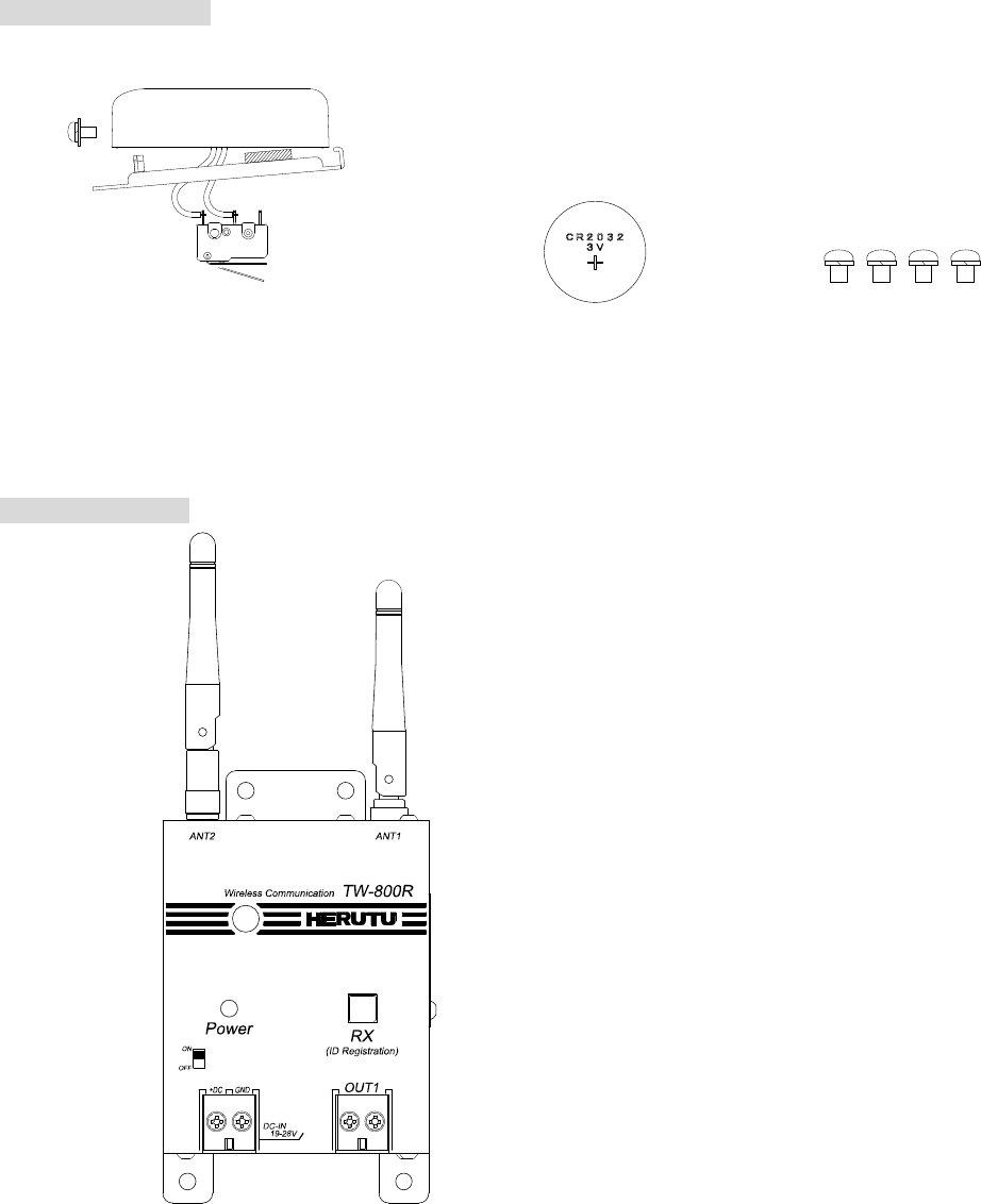
■Main part and accessories
Transmitter TW-800T
Receiver TW-800R
Coin battery CR 2032×1 Screw for fitiing M4×L5×4
TW-800T ×1
(Screw for fitting a mainpart, Limit switch)
Fitting plate×1
TW-800R ×1
TW-800
3
■Safety concerns
Safety concerns (Be sure to read)
To prevent human injury of user or damage in property from occurring, be sure to observe the precautions
shown below.
■ The degree in safety hazard and damage generated by the wrong usage while ignoring the descriptions is
classified by the following displays.
Using in an improper way while ignoring this pictorial symbol might cause a death or
serious human injury.
Using in an improper way while ignoring this pictorial symbol might cause a human injury
or property damage.
■The type of descriptions you should observe is classified by the following pictorial symbols.
This pictorial symbol indicates a “Reminder” to attract an attention.
This pictorial symbol indicates a “Prohibition” to prohibit a certain action.
■ For the usage to be commonly applied in all the models:
●Avoid using in a place with a plenty of humidity or dust. Otherwise, absorbing a dust or water
contents may cause machine trouble, fire or electrical shock.
■For handling this machine:
●This is the electronic devise or wireless radios composed of the precision parts.
Do not overhaul/remodel. It may cause accident or machine trouble.
■ For handling this machine:
●Do not use this product for the application needing the high reliability related to human lives.
●Do not use this product in a place where it is uncertain about whether or not radio waves reach.
Warning
!
Caution
!
!
!
Warning
!
TW-800
4
■For handling the power source:
Be sure to observe the following precautions to prevent the AC adapter and Power cord from being heated,
damaged, or ignited.
●Do not approximate the AC adapter and Power cord to a fire, or do not put them into a fire. The
AC adapter and Power cord can be broken or ignited, resulting in an accident.
●You can use the AC adapter and main body only with the specified power voltage to protect them
from the damage and fire accident.
●Do not use the AC adapter and main body in a wettable atmosphere. It may cause accidents or
troubles such as heating, igniting or electrical shock.
●Do not touch the AC adapter, main body, Power cord and Plug outlet with wet hands. It may
cause an accident such as electrical shock, etc.
●Do not damage the Power cord. A short-circuit or heating may cause a fire or electrical shock.
●Do not use the Power plug with dust being adhered.
A short-circuit or heating may cause a fire or electrical shock.
●Do not give a strong impact onto the AC adapter. It may cause an accident or machine failure.
●If you find out deformed AC adapter, do not use it.
It may cause an accident or machine failure.
●Do not charge this equipment in a place where flammable gas can be generated. It may
cause a fire accident.
●Never overhaul the AC adapter.
It may cause an accident or machine failure.
■When trouble happens during use:
Since it may cause a fire or electrical shock, disconnect a power plug, and immediately ask outlet store or our
company to repair.
●When smoke or abnormal odors are generated, stop using, immediately disconnect a power
plug, and ask outlet store or our company to repair.
●Once the Power cord is damaged, do not use it.
Using it as is may cause a fire or electrical shock.
!
Warning
!
TW-800
5
■Name and function of each part
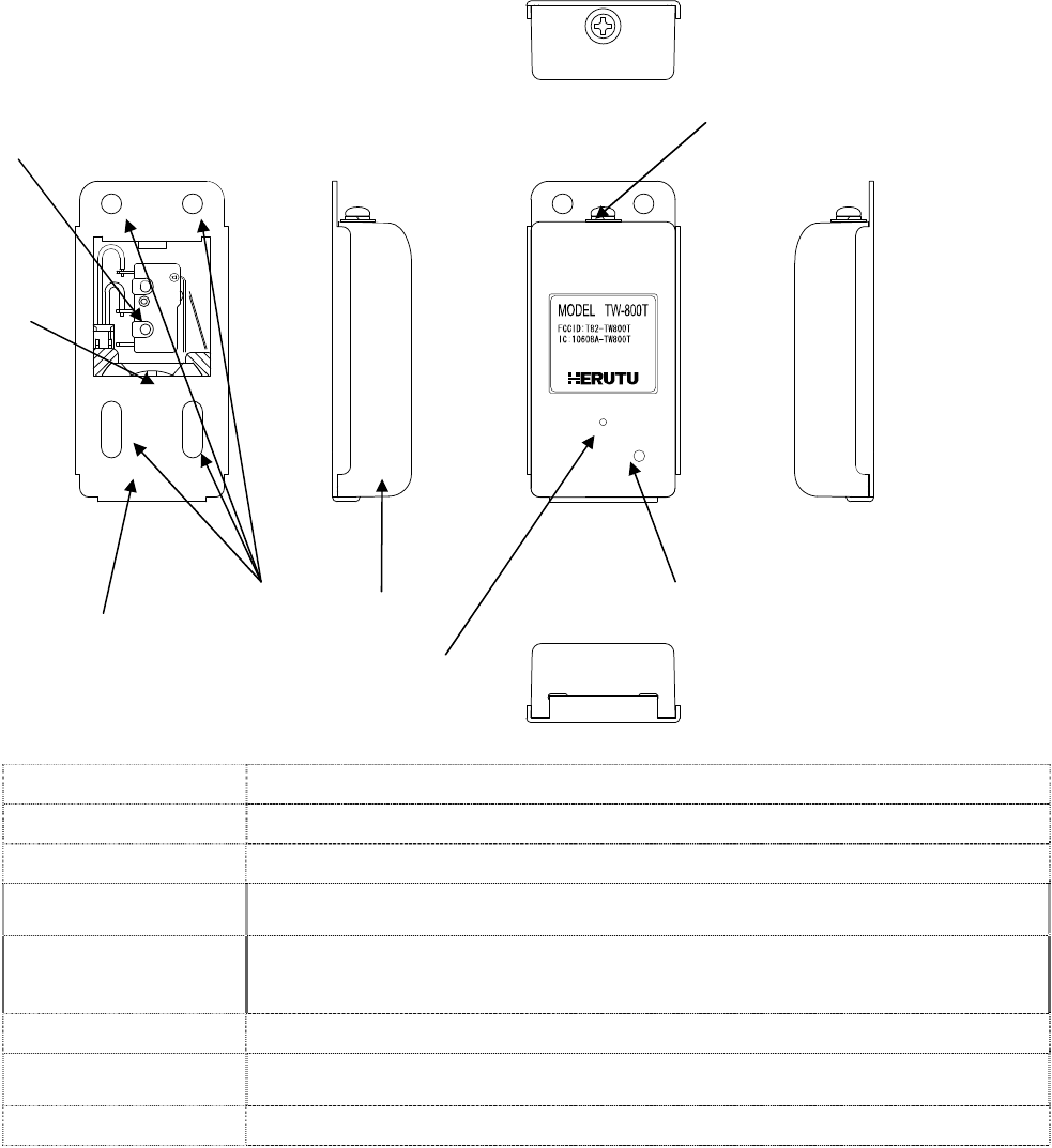
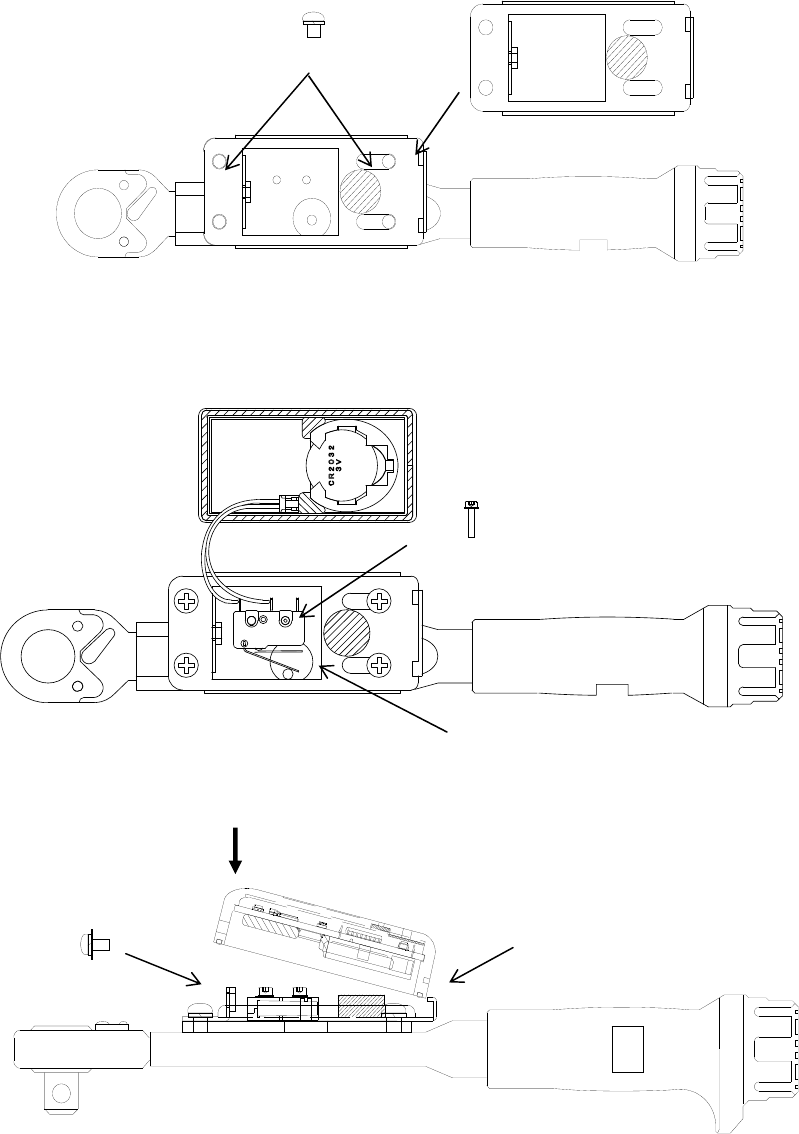
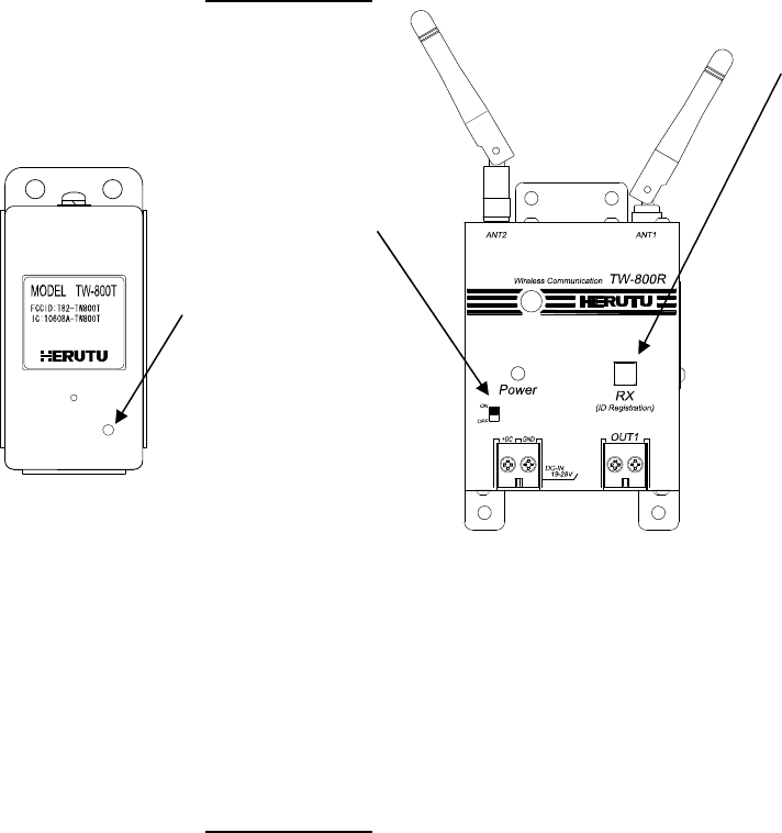
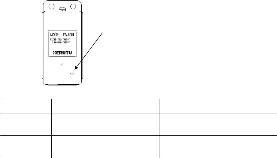
●Transmitter TW-800T
1.Seat Seat is for setting torque wrench and plier wrench and so on.
2.Hole of bracket The hole is for mounting the base of torque wrench of LS type and seat
3.Case Case for main body. It is used indestructible polypropylene materials.
4.LED(Red/Green) LED is for confirmation of communication and battery checking. Depend on the situation,
LED is lighting and flashing
5.Test switch
(Pairing switch)
For Test switch and paring switch.
6.Screw for fixing The screw is for mounting main body and seat
7.Limit switch Limit switch is for input the signal from torque wrench.
It is fixed the mount base of torque wrench by hexagon screw.
8.Battery Battery is coin battery. Type is CR-2032
1
7
2 3
4
5
6
8
TW-800
6
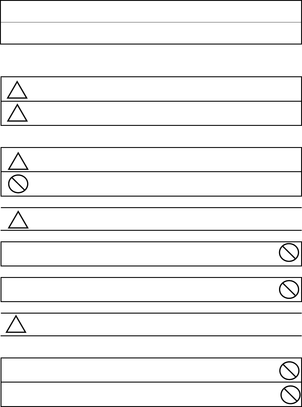
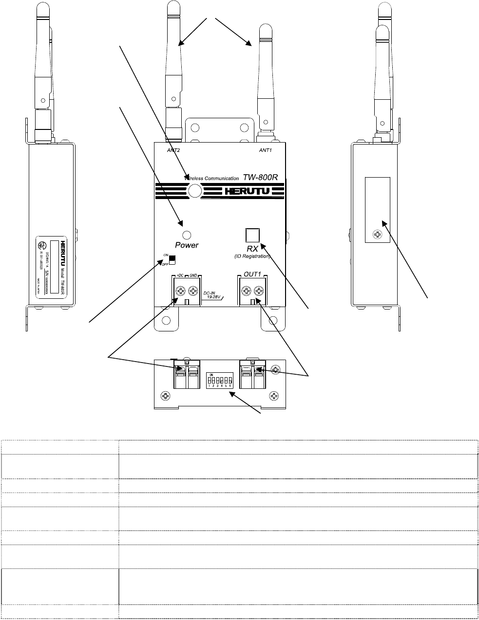
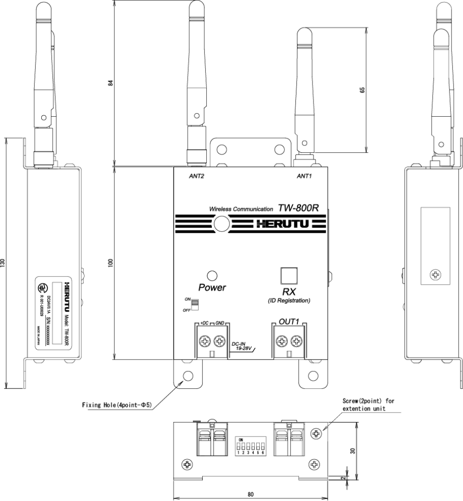
●Receiver TW-800R
1.Power switch For power ON and OFF
2.Terminal block of
power source Terminal block for power source of DC24V(M3)
3.DIP Switch For setting DIP switch(6 selection)
4.Output terminal block Photo-mos relay output terminal block(M3)
5.RX light switch:Green
(for Paring switch)
Led lights at receiving the signal from transmitter normally.
Also RX light switch is used for paring.
6.I/F for Expanding unit At connecting Expand unit, the cover is unfixed.
7.Antenna 2 antennas for Diversity type. Antennas are dipole type.
Both antennas can’t be removed.
8.Buzzer
Buzzer sounds at receiving the signal from transmitter.
It is possible to set sounds on and off, or big and small.
Sound pressure 95dB/m
9.Led of Power(Red) It lights at power ON.
1
9
2
7
5
4
6
3
8
TW-800
7
■Installation
<Installation the transmitter to torque wrench>
To install the seat
Fix the Seat with four fixing screws.
For the application with heavy oil mist, fill up the caulking agent between Wrench seat and Seat and also between
Wrench shaft and Wrench seat to protect the internal board.
Fix the Transmitter Limit SW with two hexagon socket head bolts(which was removed).
Verify that the moving range of wrench lever is well suited for the movement range of switch during the wrench
in movement.
Hook the Transmitter on the Case holder of Seat, set it with an attention being paid not to bite the cord, and fix it
with the set screw as firmly pushing the case.
Apply the screw locking agent on 2 to 3 threads of
hexagon socket head bolt.
Wrench lever
Apply the screw locking agent
onto the 2 to 3 threads of screw
edge.
The hexagon socket head bolt requires a washer.
It hooks on a case fixed nail
×4
×2

TW-800
8
<The attention and the check method on limit switch attachment>
When the lever working range of a torque wrench is small, a limit switch cannot be struck and a transmitter may
not send. In limit switch attachment, be careful enough and carry out.
<Input Judgment time for transmitter>
Transmitter don’t transmit when the signal from limit switch is within 40ms.
This function prevent transmitting the signal at striking the limit switch when the torque wrench is fallen.
When you install a limit switch and a transmitter, it can not send the signal that you strike a limit switch by your
finger. But it is based on the abovementioned processing.
In the case of tightening the limit switch in normal, the time is approx 100ms-170ms.
In the case of striking the limit switch by being fallen, the time is approx 20-30ms.
Input judgment time of transmitter is set by above cause.
<Installation the receiver>
■Install this machine in the place where it can be easily viewed from the Transmitter and also an electric wave
can be stably received.
■Set the antenna so that it is not parallel to the metal plates and keep away it from metal plates as far as
possible.
■Feed the stable power supply (DC24V) with less variation.
When you use with AC power supply, please use the AC/DC adaptor “ADB24050”of an option.
■Make a wiring for the output terminal block.
Output turns on with relay contact. Once output turns on, short-circuited condition is made between terminals.
Once the rated contact load is exceeded, inner circuit might be damaged. Use an extreme care.
Terminal block:M3(2P)
Input power source:DC24V(DC19~DC28V)
Rated load voltage AC/DC30V per point
Rated load current 0.5A per point
Contact mechanism MOS-FET/1a
Terminal block:M3(2P)
TW-800
9
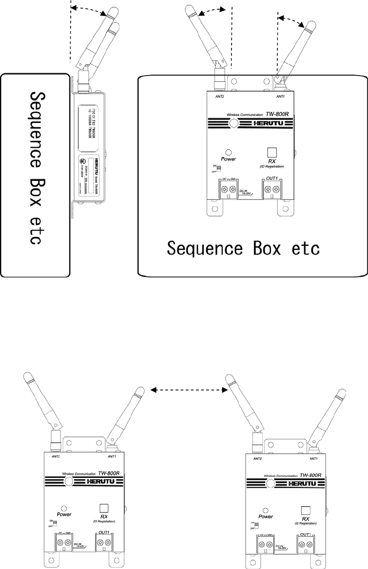
The antenna of a receiver should install so that there is no obstacle in the circumference of an antenna.
Receiver has 2 antennas and it is diversity type. Both antennas should install that there is no obstacle in the
circumference of an antenna.
Also in case of setting installation 2 receivers for parallel, it should install separately over 5cm from each antenna
at least.
Antenna should Install 30-45 degree of
the directions of the front.
An antenna is seen from the front, is opened
in the direction of outside 0-45 degree, and is
installed in it.
It should be installed separately over 5 cm at least
TW-800
10
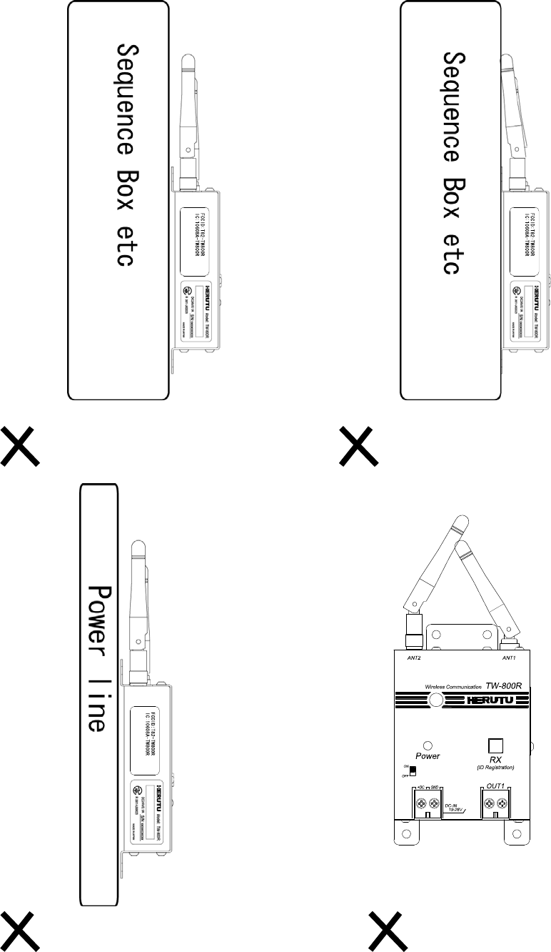
Please do not set the following installation.
It is parallel with sequence box and
antenna
It is installed bear power line.
It is touched antenna with sequence
box.
Each antennae are in touch.
TW-800
11
■Setting
It needs “pairing” a transmitter and a receiver before using. Transmitter and receiver communicate by recognizing
the other party's recognition signal by pairing.
●Pairing (Registration)
1. Power Switch is turned on pushing the lighting switch for paring of a receiver.
To enter “Pairing mode” only 10 seconds with flashing the lighting switch for pairing.
2. You continue pushing the “pairing switch” over 3secondsof transmitter by a long and slender thing.
3. It is completed the pairing between transmitter and receiver, then the lighting switch of receiver is turned off.
4. It can communicate with transmitter being pairing, you turn off the power switch of receiver once.
●Delete the pairing
1. Power Switch is turned on pushing the lighting switch for paring of a receiver.
To enter “Pairing mode” only 10 seconds with flashing the lighting switch for pairing.
2. You continue pushing the “lighting switch for pairing” over 2 seconds, then the lighting switch is turned on.
The transmitter which is register by pairing is deleted.
The lighting switch for pairing.
Power switch
Pairing switch
TW-800
12
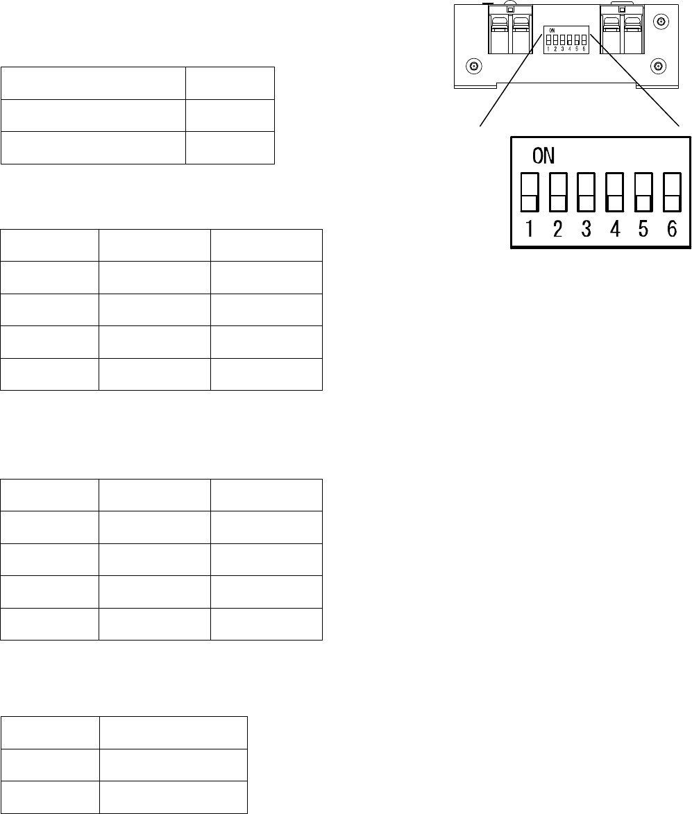
●Setting of receiver
You can set “relay output time”, “Double count protect time”, “Behavior of buzzer” by six dipswitch.
Please set by your operation.
◆Buzzer ON/OFF
◆Relay output time (4 kinds)
◆Double count protect time (4 kinds)
◆Buzzer sounds Big/Small
DIPSW 1
Buzzer does not sound ON
Buzzer sounds OFF
DIPSW 2 3
50ms OFF OFF
200ms ON OFF
400ms OFF ON
1S ON ON
DIPSW 4 5
10ms OFF OFF
200ms ON OFF
1S OFF ON
2S ON ON
DIPSW 6
Small ON
Big OFF
TW-800
13
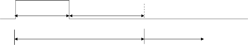
◆Caution
While the receiver output relay output or while receiver is in double count protect time, receiver transmit the
busy signal to transmitter. Then receiver doesn’t move.
When the transmitter receives the busy signal, the Green LED of transmitter flashes 3 times.
According to setting relay output time and double count protect time, a difference is made for a transmitting
intervals. Please set depend on your situation.
<Receiver>
Relay output time Double count protect time
The time receiver cannot receive
(Receiver transmits BUSY signal to transmitter.)
The time receiver can receive
TW-800
14
■How to use
1. Power switch of receiver is turned on. Please confirm the LED situation as turning off.
When the LED for receiving turns on, the transmitter is not registered by pairing. Please make a pairing with
transmitter.
2. Transmitter transmits the signal at striking the limit switch by tightening the bolts from torque wrench.
When the communication is done normally, receiver output the relay output and receiver sounds the buzzer
according to setting. Green LED of transmitter turns on 1 time.
When the communication is not done normally, receiver doesn’t move.
While the receiver output relay output or while receiver is in double count protect time, receiver transmit the
busy signal to transmitter. When the transmitter receives the busy signal, the Green LED of transmitter flashes
3 times.
Transmitter Receiver
Communication
OK Green LED 1 time flashing LED 1 time flashing
Communication
NG Red LED 10 times flashing -
BUSY Green LED 3 times flashing -
Buzzer sound time is usually for 100ms.When the relay output is set 50mses and double count protect time is
set 10mses, Buzzer sound time is 50msec.
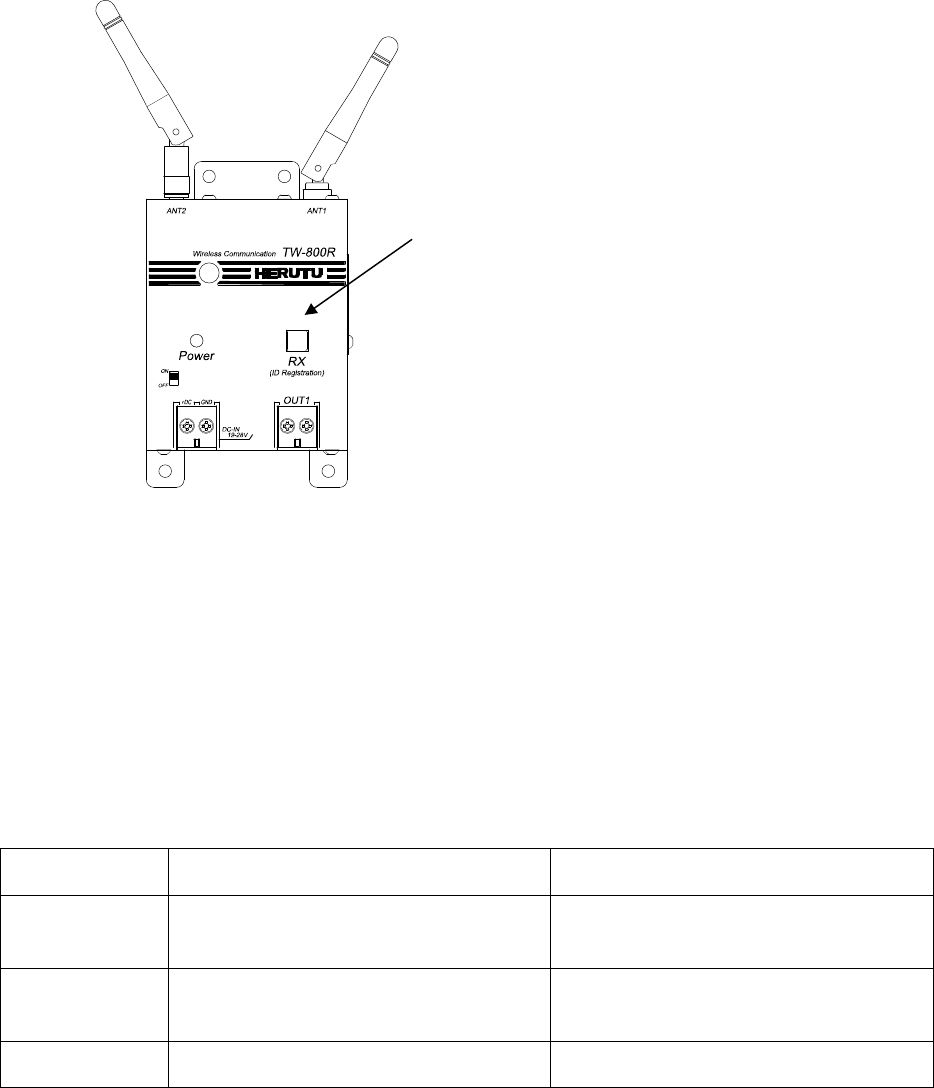
LED for receiving (Green)
(Lighting switch for pairing)
TW-800
15
●TEST SWITCH
There is a test switch for checking the battery and communication. When the transmitter transmit the signal by
test switch not limit switch, receiver doesn’t output relay output. But LED of receiver only turns on.
Also transmitter make a checking the battery at pushing the test switch. You can know the battery situation by
transmitter LED and Receiver LED
TEST SWITCH is combination with Pairing switch. To continue pushing the switch over 3 seconds, transmitter
transmits the “paring signal”. Please take care
Transmitter Receiver
Communication
check
OK: Green LED 1 time flashing
NG: Red LED 10 times flashing -
Battery power
low level Red LED 1 seconds lighting LED 2 times flashing
*Trasnmitter displays the situation of battery power low level after transmitter displays communication check
result(OK or NG).
TEST SWITCH

TW-800
16
■Specification
●Transmitter TW-800T
Items Specification
Frequency band 2,403MHz-2,478MHz
Input Limit switch*1 point
Test switch* 1point
Display LED *1 point(Red/Green
Power source Coin battery(CR2032)
Operating temperature
range Temperature 0-50 degree Humidity under 80%
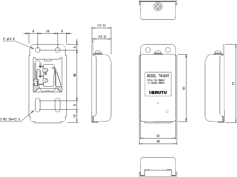
Dimension 34W*71D*17.5Hmm(Except projection)
Weight Approx 40g
Antenna Built in foundation
●Receiver TW-800R
Items Specification
Frequency band 2,403MHz-2,478MHz
Output
Contact output* 1point
Contact mechanism MOS-FET/1a
Terminal block:M3(2P)
Rated load voltage AC/DC30V per point
Rated load current 0.5A per point
Display
LED for receiving(Green) * 1point
(Combination lighting switch for pairing)
Power LED(Red) * 1point
Power source DC24V±20%(DC19-28V)
Terminal block: M3(2P)
Consumption current Under 60mA
Operation temperature
range Temperature 0-50 degree Humidity Under 80%
Dimension 80W*100H*28Dmm(Except projection)
Weight Approx 250g
Antenna Dipole antenna(Diversity type)
(It is impossible to remove.)
Switch Power switch *1 point
6 DIP switch for setting * 1point
TW-800
17
■Dimensional drawing
●Transmitter TW-800T
TW-800
18
●Receiver TW-800R

TW-800
19
■After service and Warranty
If something is wrong
If you should find anything wrong with the machine when using it under normal conditions, check the following
items and contact the outlet store through which you purchased the product or our Sales Office.
Product name / Serial No. / Working
environment,
External devices connected,
Operating sequence to error initiation,
Specific description of error, etc.
Provisions of warranty
The provisions of warranty are set forth by us for warranty of the product after shipment so that the product
can be used with a sense of security after purchased. In case our product is out of order, we will provide
repair or replacement under the provisions of warranty.
Warranty period
Besides, as long as there is not providing, the warranty period shall be 13 months after shipping the
products. During the warranty period, we will provide free-of-charge repair subject to the provisions of
warranty set forth in the warranty certificate.
If you have anything unclear about the repair or follow-up service during the warranty period, please contact
the outlet store through which you purchased the product or our Sales Office.
Scope of warranty
If the product should get out of order under the normal conditions of use by the customer, we will repair the
failed section(s) free of charge or exchange the new one free of charge subject to the provisions of warranty.
Please contact the outlet store through which you purchased the product or our Sales Office.
Also, the warranty period shall be 13 months after shipping the product or shall be 6 months after shipping
substituting goods. The warranty periods will be applied the period visited later.
Note, however, that free-of-charge repair under this warranty is limited to the hardware components of the
product. Even during the warranty period, the customer shall be responsible for repair cost if any of the
following applies:
1. Troubles or damages occurring due to improper handling by the customer, such as a fall, a shock, etc.
During transportation or movement of the product by the customer.
2. Troubles caused by overhaul or remodeling of the main body by the customer.
3. Troubles or damages caused by fire, earthquake, flood damage, or other natural disasters, as well as by
abnormal voltage.
4. Troubles resulting from any trouble of devices connected to the product, which Devices are other than
those designated by us.
5. Troubles with the accessories (AC adapter, antenna, connection cables, or the like) except the main body.
6. Repairing, adjustment, modification by except our company
TW-800
20
7. Replacement of consumables and limited-life items (including batteries).
Consumables and limited-life items include, but not limited to:
(1) Switches (limit switches, pushbutton switches, or the like)
(2) Battery cells or batteries (dry batteries, button batteries, or the like)
(3) Other items subject to consumption or limitation of life caused by use.
8. Troubles occurring due to handling against the use instructions or precautions specified in this operation
manual.
Initial defects
The period within 30 days from the date of shipping the product is defined as the initial defect period for the
product. The product will be replaced with a new one or repaired free of charge provided that it is returned
to the outlet store through which you purchased the product or our Sales Office, checked, and recognized
as having initial defects. For initial defects, we shall be responsible for the shipping cost.
But it is in Japan only. In case of purchasing the products out of Japan, it will be decided
after conference about shipping cost for returning back, insurance cost, custom duty.
Disclaimer
We will assume no liability for any damages or monetary losses, direct or indirect, arising out of troubles,
failures, or use of the product.
Repair service period
Only if we have the stock of parts for repairing, even if after finishing the warranty period, we will repair the
product within 5 years after end of production for a fee.However, we reserve the right to use substitute parts
or devices for repairing purposes if there are unavoidable reasons such as unavailability of service parts.
Others
●Independent of the warranty period, the product to be repaired shall in principle be brought into our site
because of the necessity of using measuring instruments or the like for adjustments etc., and the shipping
cost etc. incurred in bringing the product into our site shall be borne by the customer.
●In such cases where you request a trip to your place for repair or need substitute devices
during the warranty period, please contact the outlet store through which you purchased the product or our
Sales Office. We will correspond for a fee.
●We reserve the right to refuse replacement or repair if we are unable to reproduce the concerned failure at
our engineering department after receipt of a request for repair.
In addition, an additional charge may be made to the customer for the technical examination cost incurred in
reproducing the failure.
●The information in this manual, our website, catalog we supply, is subject to change without prior notice.
Please be forewarned.

HERUTU ELECTRONICS CORPORATION
〒433-8103 62-1Toyooka-cho, Kita-ku, Hamamatsu-shi, Shizuoka-ken
(Sales dept)TEL.+81-053- 438-3555 FAX. +81-53- 438-3411
URL http://www.herutu.co.jp E-mail webmaster@herutu.co.jp