Hetronic ASA3460M 450-470MHz Amplifier User Manual ASA 3 460M User s Manual
Hetronic International Inc 450-470MHz Amplifier ASA 3 460M User s Manual
Hetronic >
Manual

User’s Manual
ASA-3-460M
1. DESCRIPTION
The ASA-3 module is a switched preamplifier and variable power amplifier. It is similar to the ASA-2
module and operates for all intents and purposes, in an identical manner except for yielding higher (and
variable) RF output power. The ASA-3-460M contains a SAW filter and LNA in the receive signal path and
serves as a switched preamplifier/power amplifier, boosting both transmitted and received signals. The
version of the amplifier works with Hetronic RF modules from 450MHz to 470MHz. The addition of the
SAW filters makes band selection more precise and serves also to reject signals at other frequencies.
Note: Operation is subject to the following two conditions: (1) this device may not
cause interference, and (2) this device must accept any interference, including
interference that may cause undesired operation of the device.
FCC ID Number: LWP-ASA3460M
IC ID Number: 2119B-ASA3460M
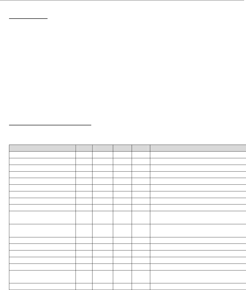
2. TECHNICAL SPECIFICATIONS
All specifications assume a 50Ω input and load.
Parameter Min Norm Max Unit Notes
Supply Voltage 3.0 4.0 5.5 V DC
Supply Current TX Mode 90 100 110 mA Configured for 100 mW output
Supply Current RX Mode 6 10 20 mA
Inp t Impedance 50 Ω
Outpu Impedance 50 Ω
Output L ad VSWR <10:1
Output Power Level 1* 15.5 17 18.5 dBm 10dBm in, J1 and J2 open
Output Power Level 2* 18.5 20 21.5 dBm 10dBm in, J1 or J2 shorted
Output Power Level 3* dBm Contact Hetronic In ustrialization
Small sign l gain
(Receiver LNA)
10 14 dB
Input Power, transmit
mode
10 11 dBm
Input Power, receive mode 0 dBm
Frequency Range 450 470 MHz
Switch line level 0 3.3 5.5 V Logic level.
Switch line high 2.7 5.5 V
Switch line low 0 0.4 V
Switch speed 1 ms Rx to Tx, ready to transmit, Tx to Rx,
ready to receive
Operating Temperature -20 +70 °C
* = see section 3.2
Note: The user is cautioned that changes or modifications not expressly approved by
the party responsible for compliance could void the user’s authority to operate the
equipment.

3. ASSEMBLY DESCRIPTION
3.1. Test / Programming Jumper Configuration
N/A – no firmware/software required for operation.
3.2. Operational Jumper Configuration
3.2.1. Default
For standard ASA-3-460M modules, only J2 should be shorted. This limits the output power to
100mW, when supplied with a 10dBm input. J3 and J4 should not be shorted. In most common
configurations, the switch line is driven by either the module or LFB board.
3.2.2. Possible Jumper Configurations
3.2.2.1. Power Output Control
Power output levels listed are typical values, and assume 50Ω input and output connections.
Please see section 2 for specifications of each power level.
J1 – Power Level 2, 20dBm (100mW) output.
J2 – Power Level 2, 20dBm (100mW) output.
J1+J2 – Power Level 3, Contact Hetronic Industrialization for specification.
Open – Power Level 1, 17dBm (50mW) output.
3.2.2.2. Switch Pull-up Select
J3 – Switch logic 10kΩ pull down select.
J4 – Switch logic 10kΩ pull up select.
J3+J4 - Invalid configuration
Open – Floating. The SWITCH pin must be driven by an external source for proper
operation.
4. Connection Diagram
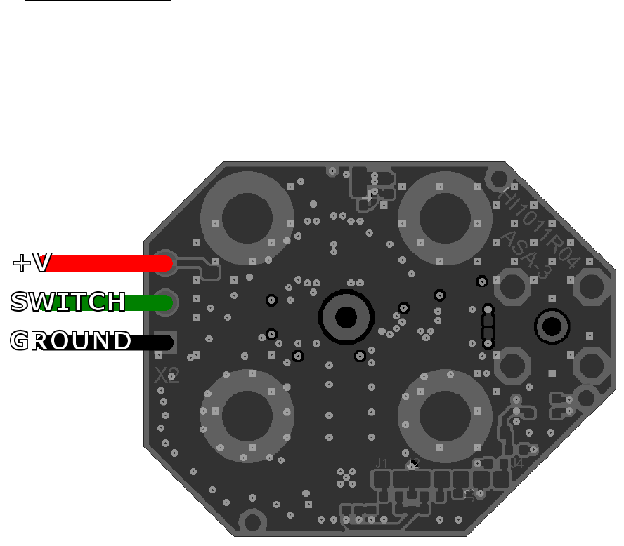
4.1. Internal Connections
The below wiring connections must extend from the bottom side of the board.
V+ - Positive power Supply
Switch – Rx (LNA)/Tx (PA) select
GND – Negative power supply
Figure 1, Wire Attachment, bottom view. Wiring must extend from the bottom side.
4.2. External Connector
These external, RF connections are shown below in Figure 2.
Antenna Connector – TNC, standard polarity. This component is designed for screw-mounting
to a bulkhead TNC connector, using appropriate spacers. The top-side of the PCB faces this
connector.
RF module connector – SMB, standard polarity. This component is soldered to the ASA-3-
460M PCB with the connector extending from the bottom side.
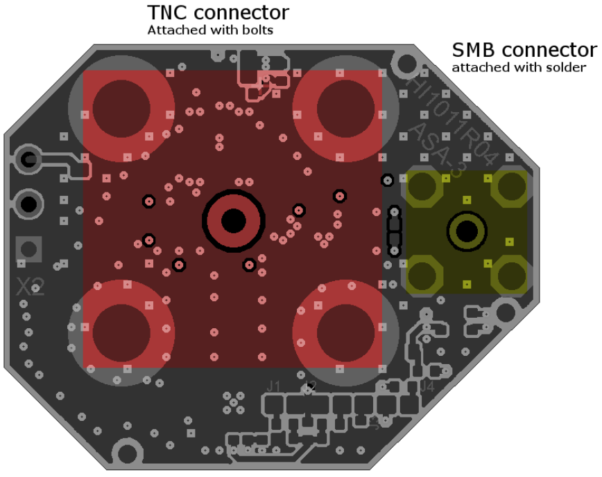
Figure 2, External RF connector placement, bottom side of PCB shown