Hetronic MFS-TX-2G4 Stellar Transmitter User Manual User s Manual MFS TX 2G4
Hetronic International Inc Stellar Transmitter User s Manual MFS TX 2G4
Hetronic >
User manual

User’s Manual
MFS-TX-2G4

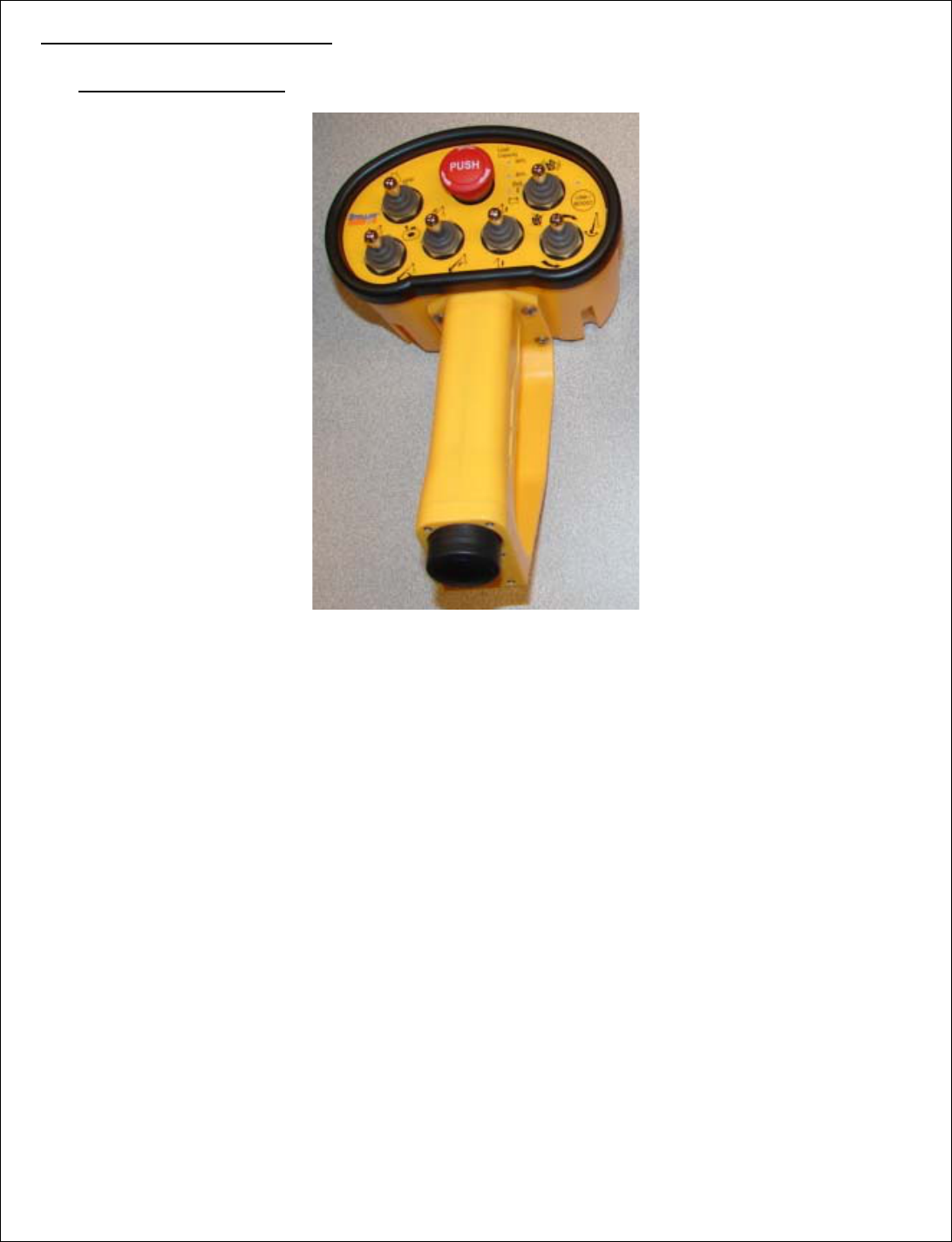
1. DESCRIPTION
The MFS-TX-2G4 is a 2.4GHz MFS Transmitter with 24 digital channel inputs. Four of the inputs
may be used with a 4-bit gray code trigger. The transmitter uses a 2.4GHz DSSS transceiver for RF
transmission and reception. The 2 operation channels (primary and secondary) can be set to any 2 of
16 available channels. The transmission duty cycle is adjustable from 1-10%. Additionally, this unit
always receives feedback which may be used to control optional status LEDs and/or vibration motor.
Note: Operation is subject to the following two conditions: (1) this device may not
cause interference, and (2) this device must accept any interference, including
interference that may cause undesired operation of the device.
2. TECHNICAL SPECIFICATIONS
Temperature Range -20°C to +70°C
Supply Voltage Range 2-5 VDC
Supply Current 20mA max
40mA for 5 seconds on startup
Outputs 1 Pulsed Vibration Motor
5 Status LEDs (3 Feedback Controlled)
RF/Cable Backup Control Data
Inputs 24 Digital TTL Inputs
1 Optional Label Switch Input
RF/Cable Backup Feedback
Note: The user is cautioned that changes or modifications not expressly approved by
the party responsible for compliance could void the user’s authority to operate the
equipment.
3. FUNCTIONAL DESCRIPTION
Transmitter Operation
• System power is initially off. Activation of any switch attached to VSW will power up the coder.
• If a switch is on when the battery pack is installed, the coder will light the Red LED and prevent
operation until the switch is released or fixed.
• After activation, the coder will automatically power down while idle. This timeout is adjustable via
H-Link.
• The coder is a passive transmitter which enters transmission cycles based on the programmed duty
cycle.
• Each transmission cycle produces two transmissions. One occurs on the primary channel while the
other occurs on the secondary channel. Immediately after each transmission, the coder listens for
feedback from the decoder for up to 3ms. The Green or Red LED will toggle for each frame that is
transmitted.
• After each transmit/receive pulse, the radio is disabled to save power.
• Pressing the stop button (DK31/DK32) will disconnect the battery and force stop frames to be sent
until the unit discharges.
• DK1 is a start function. This button can be used to reset receiver errors (Overload/ Main Contact
error) or to perform the learning operation.
• DK3-18 are regular digital channels.
• DK19-22 can be used as a 4 bit grey code trigger or regular digital channels.
• If the battery level drops below the set low-voltage level, the coder will light the Red LED.
• If the battery level drops below the critical level, the transmitter will turn off the Green LED and
blink the Red Led while sending Stop frames. The power will be turned off after 2 seconds or after
all switches are released.