Hetronic MFSHL915 Handheld Transmitter User Manual Revised
Hetronic International Inc Handheld Transmitter Users Manual Revised
Hetronic >
Users Manual Revised

User’s Manual
MFSHL915
Handheld Transmitter

1. DESCRIPTION
The MFSHL-915 Handheld Transmitter has a coder board with 24 digital channel inputs. Four of the
inputs can be used for a gray code trigger. It includes a Low Voltage Indicator (LVI) warning, 1%
duty cycle, and 2 seconds turn off time. It also includes switch detection on power up to ensure that
no switch is active when the battery is inserted. The RF section uses FM-RF with 915MHz frequency
and 76800 baud rate.
Note: Operation is subject to the following two conditions: (1) this device may not
cause interference, and (2) this device must accept any interference that may cause
undesired operation of the device.
2. TECHNICAL SPECIFICATIONS
Note: The user is cautioned that changes or modifications not expressly approved by
the party responsible for compliance could void the user’s authority to operate the
equipment.
Temperature Range -20o to +70o Celsius
Supply Voltage Range 2-5 VDC
Supply Current 42mA max
28mA for 5 seconds on startup
Outputs RF-Data
2 LED
Inputs 24 digital
RF Specifications
Frequency 915.0 MHz
Modulation FM-Binary FSK
Deviation 64KHz
Output Power 5dBm
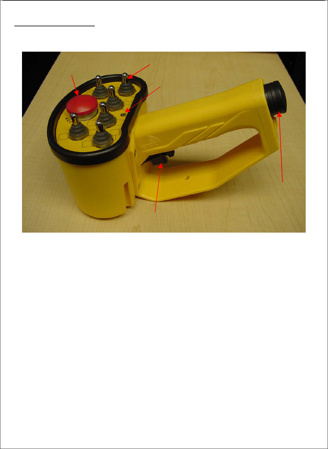
3. TRANSMITTER PARTS
Battery Holder
(2AA)
Toggle Switches (6)
E-Stop
switch
LED indicator
Gray-code trigger
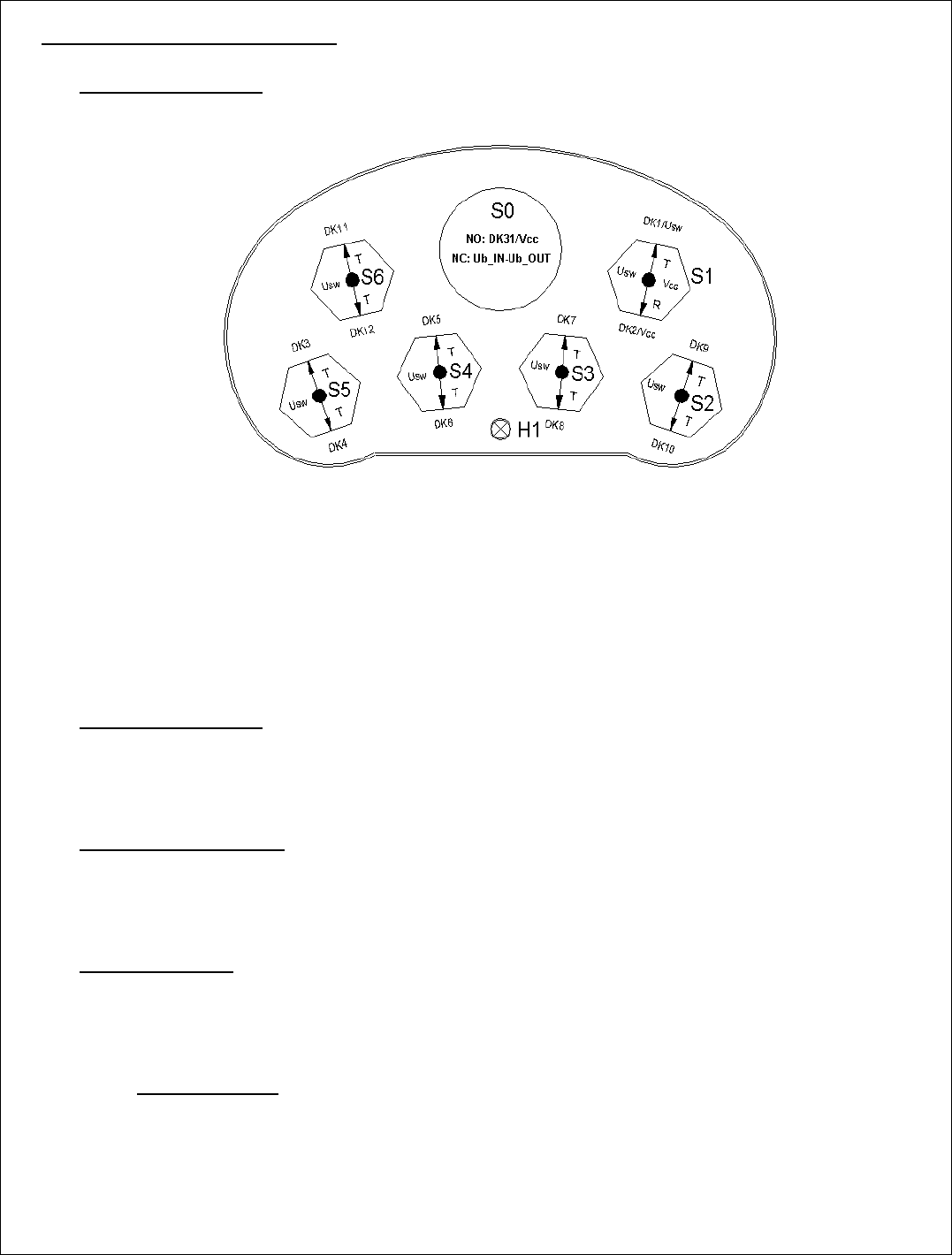
4. FUNCTIONAL DESCRIPTION
4.1. General Description
• This transmitter is designed to transmit with RF-transmission duty cycle of 1%.
• The transmitter will turn off automatically 2 seconds after all switches are released.
• DK31/32 (ESTOP) is an emergency stop button that has priority above all other inputs.
• DK1 is a start function. This button can be used to reset error in the receiver (Overload/ Main
Contact error).
• DK3-18 are regular digital channels.
• DK19-22 can be used as a 4-bit grey code trigger or regular digital channels.
4.2. Switch Error Detect
The unit contains a switch detection that detects when a switch is broken. If a switch is active when
a battery is inserted the unit will go into an error state. The RED LED will come on and stay on until
the active switch is turned off.
4.3. Low Voltage Indicator
The unit has a low battery detection function. Once the battery level becomes low the RED LED will
come on solid while the GREEN LED keeps blinking with every telegram. If the voltage level
reaches a critical level, the transmitter will only send ESTOP telegrams.
4.4. LED Description
Yellow Flashing: Unit is Operating
Yellow Flashing/Red Flashing/Green Flashing: Memory Error
Red Solid (on power up): Switch Error
(Note: Yellow LED is not visible unless the unit is opened)
4.4.1. Transmit Mode
Green Flashing: Telegram Transmitted
Red ON, Green Flashing: Low Voltage Pre Warning
Red Flashing: E-stop Transmission