Hetronic MILLER-HC Wireless Handheld Controller User Manual User s Manual Miller Hand Control
Hetronic International Inc Wireless Handheld Controller User s Manual Miller Hand Control
Hetronic >
manual

User’s Manual
Miller Hand Control
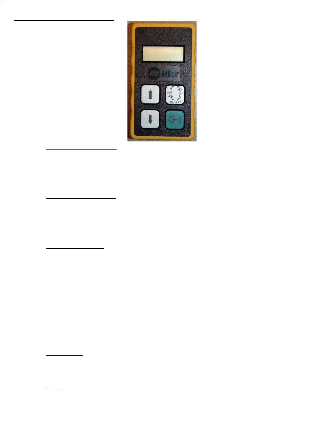
1. DESCRIPTION
The Miller Hand Control (M-TX-Mini) is a four-button transmitter for the Hetronic Mini housing.
The board combines a four-character / seven segment LCD and Blue LED to provide the user
information. The module is equipped with variable R.F. duty cycle, and variable turn off time. It
operates on 2 selected channels from 16 selectable 2.4GHz frequency channels.
Note: Operation is subject to the following two conditions: (1) this device may not
cause interference, and (2) this device must accept any interference that may cause
undesired operation of the device.
2. TECHNICAL SPECIFICATIONS
Note: The user is cautioned that changes or modifications not expressly approved by
the party responsible for compliance could void the user’s authority to operate the
equipment.
Temperature Range -30o to +70o Celsius
Temperature Range Display -20o to +70o Celsius
Supply Voltage Range 3.4-5 VDC
Supply Current 10mA max after 5 seconds startup
Outputs 2,4Ghz RF-Data Out 1-10% Duty Cycle
Inputs 2,4Ghz RF-Data In
Low voltage detection level 3.4~3.5Vdc (Adjustable to Low/Mid/High)
3. FUNCTIONAL DESCRIPTION
3.1.Transmitter Operation
This Transmitter is designed to be used with RF-transmission duty cycle of 1% to 10%.
Upon closing any one of the four switches, the coder will turn ON and start RF-transmission of
non-Estop telegrams. Feedback from the matched Receiver can be displayed on the
Transmitter’s LCD and control the LED output.
3.2.Low Voltage Indicator
The unit has a low battery detection function. Low battery can be displayed on the LCD.
The level can be programmed (the actual voltage is not programmed, just Short, Medium,
Long delay before the batteries die). If the input voltage reaches a critical level (3.4~3.5Vdc)
the transmitter will automatically shutdown.
3.3.Learning Function
The system has a learning function to allow users to pair a decoder to a coder’s channel and
address settings. The procedure to use the learning function is as follows:
3.3.1. Press and hold the learning button on the Receiver.
3.3.2. Press the down button and hold until LRN is displayed.
3.3.3. The decoder’s green LED will begin blinking rapidly to indicate data is being
received from the coder and that the learning function is complete.
3.3.4. Release the decoder’s learning switch.
NOTE: Learning is only possible when the transmitter display reads LRN.
The Receiver will only learn if the Coder is close to the Receiver, two meters or less.
The address of the RX and M-TX-MINI are combined so only this pair is bound.
3.4.LED output
A Blue indicator LED is located at the top of the Transmitter housing and indicates the Main
Contact is closed on the decoder.
3.5.LCD
A 51 x 26mm LCD is provided for feedback and other user information with four seven-
segment characters and a decimal at P2.