Hetronic MILLER-RX Wireless Receiver 14 Pin User Manual User s Manual Miller Receiver
Hetronic International Inc Wireless Receiver 14 Pin User s Manual Miller Receiver
Hetronic >
manual

User’s Manual
Miller Receiver
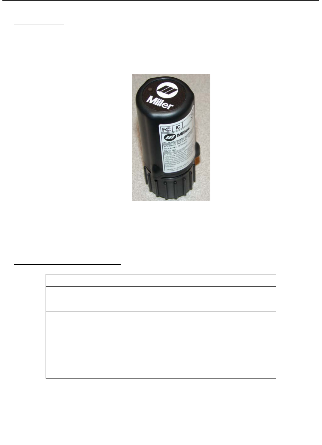
1. DESCRIPTION
The Miller Receiver have a Solid-State Main Contact (AC/DC), two analog inputs, one scalable
analog output (0~10Vdc, 8-bit resolution), 2.4GHz frequency, with address learning. A Watchdog IC
for monitoring and resetting the Micro Controller. The Receiver works in combination with the Miller
Foot Control and Miller Hand Control.
Note: Operation is subject to the following two conditions: (1) this device may not
cause interference, and (2) this device must accept any interference that may cause
undesired operation of the device.
2. TECHNICAL SPECIFICATIONS
Note: The user is cautioned that changes or modifications not expressly approved by
the party responsible for compliance could void the user’s authority to operate the
equipment.
Temperature Range -30o to +70o Celsius
Supply Voltage Range 12-30VAC or 12-30VDC (50Vdc peak)
Supply Current 28mAdc or less
Inputs 2,4Ghz RF-Data In
Potentiometer Input Voltage (0 to 10Vdc)
Two analog inputs (0 to 10Vdc)
Address learn SW
Outputs 2,4Ghz RF-Data Out
Potentiometer Output Voltage (0 to 10Vdc)
Relay Output Solid State 1Amax AC or DC
Green LED (Function and Signal Indicator)

3. FUNCTIONAL DESCRIPTION
3.1. Receiver Operation
• The main power supply is 12 to 30Vac coming from the welding machine. This supply is also
used as the supply for the Main Contact output.
• The DK assigned for the relay output is configurable. By default, it is assigned to DK3 that is
the safety-DK transmitted by the M-TX and M-Mini-TX boards.
• The time for the relay output to turn ON (ON delay) and to turn OFF (OFF delay) is adjustable.
By default, there is no delay set (ON delay = 0ms, while OFF delay = 0ms).
• The DC analog output is controlled by the 8-bit data (256 steps) and the assigned safety DK.
The analog output range depends on the DC supply coming from the welding machine. This
reference input supply is adjustable from 0 to 10V. If the reference input supply is set to 1V,
the analog output will be 0~1V with the same 8-bit resolution. The DK assigned to the 8 bits is
fixed to DK17~DK24 with DK17 as the LSB. The default safety channel is DK3.
• The analog output ramp time is adjustable. By default, minimum ramp time of 100ms is set to
make the output increment/decrement transition smooth. Ramp time is the total time for the
output to reach maximum when it is initially minimum. Ramp time is only valid while safety
DK is active. If the safety DK is turned OFF, the analog output will be set to minimum without
considering ramp time.
• The receiver is capable of learning the transmitter address and channels using its learning
button. Details of this function described on following sections.
3.2. Learning Function
The system has a learning function to allow users to pair (bind) a Transmitter to a Receiver’s
frequency and address. The procedure to use the learning function is as follows:
1. Bring the Transmitter to within 2 meters of Receiver.
2. Press and hold the learn button on the Receiver.
3. Press Foot Pedal to maximum travel stop and hold for four seconds or adjust Mini-
TX display to minimum and hold down button for four seconds.
4. Release the Receiver’s learn switch.
5. The decoder’s green LED will begin blinking rapidly to indicate data is received
from the Transmitter and the learning function is complete.
6. For safety the Main Contact will not close until the Foot Pedal is turned on a second
time.
Learning is only possible during the first 2 seconds that the Footpedal Transmitter is at maximum
analog output and the Receiver detects a high level of R.F. strength (indicating the transmitter is
within a 3 meter range). After address learning, the Transmitter and Receiver pair combine the
Receiver address and Transmitter address to make a unique address to prevent errant Binding with
another device.
LED Description
Receive Mode
Green LED Flashing at a rapid interval: Active Telegram is being received. Green LED is toggled every
time a valid telegram is received. Green LED toggles slower when receiving from a Mini-TX in standby
mode.
Idle Mode
Green LED on solid.

4. FCC REQUIREMENTS FOR INFORMATION TO THE USER
The users manual or instruction manual shall caution the user that changes or modifications to
the equipment not expressly approved by the party responsible for the grant of equipment
authorization issued by the FCC could void the user's authority to operate the equipment under
the grant of equipment authorization:
Warning: Changes or modifications to this device not expressly approved by Hetronic
could void the users authority to operate the device under the FCC Equipment
Authorization.
Warning: Co-location of this modular transmitter with any other transmitter is prohibited
without a Class II permissive change to both transmitters.
5. OEM PRODUCT LABELING
If the label on the modular transmitter is not visible from the exterior of any enclosure into which
it is installed, the following label must be added to the exterior of the final product or device,
“Contains FCC ID: LW9-MILLER-RX.