Hewlett Packard Enterprise 550-10016-7 WLAN atbtg mini-PCI module User Manual M365 415

Hewlett-Packard Co WLAN atbtg mini-PCI module M365 415

Contents

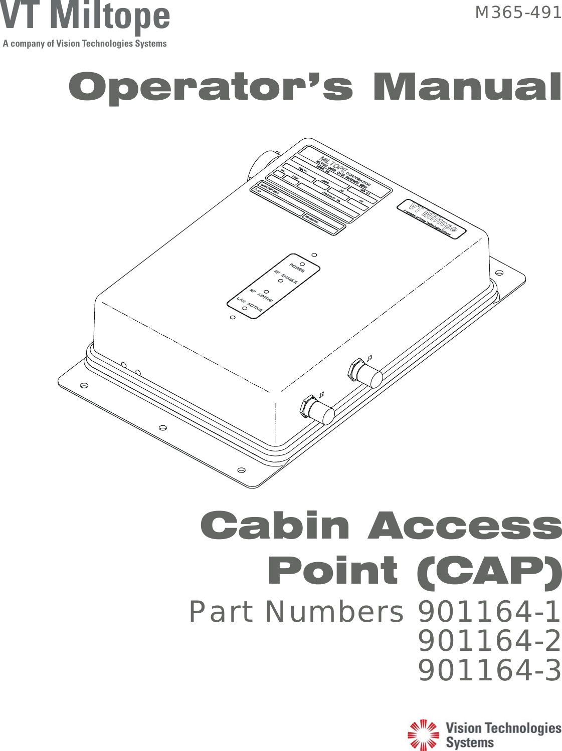
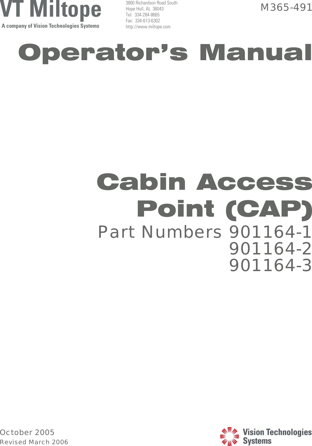
CAP Operating Manual

 VT MiltopeA company of Vision Technologies Systems M365-491 Operator’s Manual     Cabin Access Point (CAP)  Part Numbers 901164-1 901164-2 901164-3
October 2005 Revised March 2006   VT MiltopeA company of Vision Technologies Systems 3800 Richardson Road South Hope Hull, AL  36043 Tel:  334-284-8665 Fax:  334-613-6302 http://www.miltope.com M365-491 Operator’s Manual             Cabin Access Point (CAP) Part Numbers 901164-1 901164-2 901164-3
M365-491 Operator’s Manual   Table of Contents  i  March/2006 TABLE OF CONTENTS  Chapter/Paragraph Page   LIST OF FIGURES.............................................................................................................iv   LIST OF TABLES...............................................................................................................iv  1 GENERAL INFORMATION...........................................................................................1-1   1-1  Introduction..................................................................................................1-1  1-2  Typographic Conventions............................................................................1-1   1-2.1  Keyboard Entries and Software Commands ................................................1-1  1-2.2  Variables ......................................................................................................1-2  1-2.3  Screen Display .............................................................................................1-2  1-3  Terminology.................................................................................................1-2  1-4  Equipment Description ................................................................................1-2   1-5  Building a Wireless Local Area Network (WLAN).....................................1-3   1-5.1  Connecting to a Wired Local Area Network (LAN)....................................1-4  1-5.2  Connecting to a Wired Server......................................................................1-4  1-5.3  Instant Infrastructure....................................................................................1-5   1-5.4  Building a Multi-Cell Wireless Network.....................................................1-5   1-6  Building a Wireless Link .............................................................................1-5  1-7  Security ........................................................................................................1-6  1-8  Specifications...............................................................................................1-7  1-9  Approved Antennas .....................................................................................1-9  1-10  Available Software and Manuals.................................................................1-12   1-11  Tools and Test Equipment Required............................................................1-13  2 EQUIPMENT SETUP.......................................................................................................2-1   2-1  Introduction..................................................................................................2-1   2-2  Unpacking and Inspection............................................................................2-1  2-3  Initial Setup..................................................................................................2-1  2-4  Configuration...............................................................................................2-1  3 INSTALLATION...............................................................................................................3-1   3-1  Introduction..................................................................................................3-1  3-2  Mounting......................................................................................................3-1  3-2.1  CAP Unit......................................................................................................3-1   3-2.2  Indoor Cabin Antenna..................................................................................3-1  3-2.3  Outdoor Antenna..........................................................................................3-1   3-3  Connecting the CAP ....................................................................................3-11   3-3.1  Input Power Requirements...........................................................................3-11
Operator’s Manual  M365-491   ii  Table of Contents March/2006 TABLE OF CONTENTS (Cont’d.)  Chapter/Paragraph Page    3-3.2  10/100BaseT Ethernet Local Area Network (LAN) Ports...........................3-13   3-3.3  RF (Antenna) Output ...................................................................................3-14  3-3.4  Discrete Inputs .............................................................................................3-14  3-3.5  Discrete Outputs...........................................................................................3-15  3-3.6  Reset Input ...................................................................................................3-15  3-4  Configuring Wireless Client Stations (CWLU Configuration)....................3-15   3-5  Configuring the Ground-Based Network (TWLU Configuration) ..............3-15  4 OPERATION .....................................................................................................................4-1   4-1  Introduction..................................................................................................4-1  4-2  Indicators......................................................................................................4-1  4-3  Operating Instructions..................................................................................4-1  4-4  Power Up .....................................................................................................4-1   4-5  Checking the Status of Your CAP ...............................................................4-1  5 OPERATOR MAINTENANCE .......................................................................................5-1   5-1  Introduction..................................................................................................5-1  5-2  Inspection.....................................................................................................5-1  5-3  Cleaning Exterior Surfaces ..........................................................................5-1  5-3.1  Materials Required.......................................................................................5-1  5-3.2  Cleaning Procedure......................................................................................5-1   5-4  Installing Operating Software ......................................................................5-1  6 TROUBLESHOOTING....................................................................................................6-1   6-1  Introduction..................................................................................................6-1   6-2  Client Station Problems ...............................................................................6-1   6-2.1  Wireless Client Station Cannot Establish a Wireless Link  With the CAP...............................................................................................6-1   6-2.2  IP Address Mismatch...................................................................................6-2   6-2.3  Wireless Client Stations Cannot Connect to the Internet Via the CAP.......6-2   6-2.4  Computers Cannot Share Data or Resources With Other Computers .........6-3   6-2.5  Web Browser Cannot Connect to Management Tool..................................6-3  6-2.6  Low Throughput ..........................................................................................6-4  6-3  CAP Problems..............................................................................................6-4   6-3.1  CAP Allows Any Station to Connect, Regardless of Network  Name Being Used ........................................................................................6-4  6-3.2  Lost Administrator Password.......................................................................6-4
M365-491 Operator’s Manual   Table of Contents  iii  October/2005 TABLE OF CONTENTS (Cont’d.)  Chapter/Paragraph Page  7  REGULATORY, WIRELESS INTEROPERABILITY, AND  HEALTH INFORMATION.............................................................................................7-1   7-1  Regulatory Information...............................................................................7-1  7-2  Wireless Interoperability.............................................................................7-3  7-3  Health Information......................................................................................7-3   GLOSSARY.......................................................................................................................G-1
Operator’s Manual  M365-491   iv  Table of Contents March/2006  LIST OF FIGURES  Figure   Page  1-1  Cabin Access Point (CAP)...................................................................................................1-3 1-2  Connecting to a Wired LAN ................................................................................................1-4 1-3  Connecting to a Wired Server..............................................................................................1-4 1-4  Creating an Instant Infrastructure.........................................................................................1-5 1-5 Multi-Cell Wireless Network...............................................................................................1-6 1-6 Aircraft-to-Ground Wireless Link .......................................................................................1-6 2-1 CAP Packaging....................................................................................................................2-2 3-1  CAP Outline Dimensions.....................................................................................................3-2 3-2  Indoor Cabin Antenna Part Numbers 901167-1 and 901167-2 Outline Dimensions ..........3-2 3-3  Antenna Part Number 901167-1 Radiation Pattern .............................................................3-3 3-4  Antenna Part Number 901167-2 Radiation Pattern .............................................................3-5 3-5  Outdoor Antenna Part Number 901058-1 Outline Dimensions...........................................3-7 3-6  Antenna Part Number 901058-1 Radiation Pattern (2.35 GHz)..........................................3-8 3-7  Outdoor Antenna Part Number 901563-2 Outline Dimensions...........................................3-9 3-8  Antenna Part Number 901563-2 Radiation Pattern .............................................................3-10 3-9 Connector Locations ............................................................................................................3-11 3-10  RJ45 Male Connector Front View.......................................................................................3-13 4-1 CAP Indicators.....................................................................................................................4-2 5-1 Test Cable ............................................................................................................................5-2 5-2  Test Box Schematic Diagram ..............................................................................................5-3 5-3 Test Setup.............................................................................................................................5-4   LIST OF TABLES  Table Page  1-1  CAP Unit Specifications......................................................................................................1-7 1-2 Specification Compliance....................................................................................................1-8 1-3 Approved Antennas .............................................................................................................1-9 1-4  Antenna Part Number 901167-1 Specifications...................................................................1-10 1-5  Antenna Part Number 901167-2 Specifications...................................................................1-10 1-6  Antenna Part Number 901058-1 Specifications...................................................................1-11 1-7  Antenna Part Number 901563-2 Specifications...................................................................1-12 1-8 Available Software and Manuals.........................................................................................1-13 3-1  I/O Connector J1 Pin Assignments......................................................................................3-12 3-2  CAP I/O Connector J1 to RJ45 Male Cross Reference .......................................................3-13 3-3  RF Output Connectors J2 and J3 Pin Assignments .............................................................3-14 4-1 CAP Indicators.....................................................................................................................4-2 5-1  Equipment Required for Software Installation ....................................................................5-2
M365-491 Operator’s Manual   Chapter 1  1-1 General Information  October/2005 CHAPTER 1  GENERAL INFORMATION  1-1  INTRODUCTION This manual provides instructions for setup, installation, operation, and operator maintenance of Cabin Access Point (CAP), part numbers 901164-1, 901164-2, and 901164-3, hereinafter referred to as the CAP.  Configuration instructions for the operating software are provided in the operator’s manual for your software.  This manual is divided into seven chapters as follows:  a. Chapter 1, General Information.  This chapter provides a description and specifications for the CAP.  Included is a description of the typographic conventions used to present information in this manual.  b. Chapter 2, Equipment Setup.  This chapter provides instructions for unpacking, inspecting, and initial setup of your CAP.  c. Chapter 3, Installation.  This chapter provides instructions for installation.  CAP mounting and connection instructions are provided in this chapter.  d. Chapter 4, Operation.  This chapter provides the information you need to become familiar with your CAP.  Included are descriptions of indicators along with instructions to operate your CAP.  e. Chapter 5, Operator Maintenance.  This chapter provides instructions for the periodic tasks the operator should perform to maintain the CAP in proper working condition.  f. Chapter 6, Troubleshooting.  This chapter provides instructions for troubleshooting that can be performed by the operator.  g. Chapter 7, Regulatory, Wireless Interoperability, and Health Information.  This chapter provides information on international regulations, wireless interoperability standards, and radio frequency (RF) health issues.  1-2  TYPOGRAPHIC CONVENTIONS Various type styles are used in this manual to present instructions and indicate responses.  The following paragraphs define the conventions used.  1-2.1   Keyboard Entries and Software Commands Keyboard entries and software commands are presented in boldface type.  Instructions to press a key that performs a function have the name of the key enclosed in < > symbols.  For example, instructions to type the command “DIR” followed by pressing the Enter key are presented as follows:   Type DIR <Enter>
Operator’s Manual  M365-491   1-2  Chapter 1 October/2005 General Information 1-2.2  Variables Variable expressions or terms that are user defined are presented in italic type.  For example, an instruction to enter a path followed by a backslash, followed by a filename, followed by pressing the Enter key is presented as follows:   Type path\filename <Enter>  1-2.3  Screen Display Responses that are displayed on a computer screen are presented in a sans-serif typeface.  For example, if the word “READY” is to be displayed on the screen, it is presented as follows:    The display will read READY.  1-3  TERMINOLOGY The following terms are used frequently throughout this manual:  • Client Station:  Any computer that uses the services provided by the CAP.  This can be a computer with a wireless Local Area Network (LAN) card accessing the CAP directly, or a computer on a wired LAN that is connected to the CAP. • Management Station:  Any computer that can access the CAP management tool. • Wireless Cell:  The area in which the CAP provides a wireless signal. 1-4  EQUIPMENT DESCRIPTION The Cabin Access Point (CAP) (Figure 1-1) is a wireless communication device designed for use in airborne environments.  The CAP utilizes Direct Sequence Spread Spectrum (DSSS) radio technology in the 2.4-GHz Industrial, Scientific and Medical (ISM) radio frequency spectrum to communicate with IEEE 802.11b compliant wireless devices.  The CAP utilizes Orthogonal Frequency Division Multiplexing (OFDM) radio technology in the 2.4-GHz ISM radio frequency spectrum to communicate with IEEE 802.11g compliant wireless devices and in the 5-GHz ISM frequency spectrum to communicate with IEEE 802.11a compliant wireless devices.  The CAP provides a bridge between the aircraft IEEE 802.3 compliant wired Ethernet LAN and wireless devices.  Two aircraft level discrete inputs are provided for remote on/off control and RF enable/disable.  Two discrete outputs provide operational status.  Operation of the CAP is controlled by operating software.  The CAP can be configured with CAP operating software to configure the CAP as a cabin wireless LAN unit (CWLU) to create a wireless local area network (WLAN) aboard the aircraft, or with wireless access bridge (WAB) operating software to configure the CAP as a terminal wireless LAN unit (TWLU) to establish a wireless bridge between the aircraft network and a ground-based network.  The part number for the software installed in your CAP is indicated on the software label located on the top of the CAP unit.
M365-491 Operator’s Manual   Chapter 1  1-3 General Information  October/2005  0407231-  Figure 1-1.  Cabin Access Point (CAP)  1-5   BUILDING A WIRELESS LOCAL AREA NETWORK (WLAN) Configured as a CWLU, the CAP enables you to create a WLAN to link all your computers so that they can share data and resources.  The CAP contains two radio frequency (RF) transmitter/receivers (tranceivers).  Each tranceiver uses radio waves in the 2.4 GHz band to communicate with IEEE 802.11b and IEEE 802.11g compliant client stations or in the 5 GHz band to communicate with IEEE 802.11a compliant client stations.  Each transceiver is independently configurable for 2.4 GHz or 5 GHz operation.  Radio waves cannot penetrate metal, instead they are reflected.  This means that the CAP is able to transmit through wood or plaster walls, and closed windows.  However, the metal skin of the aircraft or metal partitions may block transmissions, or reduce signal quality by creating reflections.  To serve users separated by metal partitions will require a separate CAP unit in each area.  The CAP provides IEEE 802.11b and IEEE 802.11g wireless network coverage in a radius of up to 100 meters (300 feet) and IEEE 802.11a wireless network coverage in a radius of 30 meters (100 feet), regardless of the orientation of the device.  This is called a wireless cell.  To maximize coverage of the cell, the CAP is best installed in an open area with as few obstructions as possible.  Try to choose a location that is central to the area being served.  The following paragraphs provide an overview of the different types of connections you can make using the CAP.
Operator’s Manual  M365-491   1-4  Chapter 1 October/2005 General Information  1-5.1   Connecting to a Wired Local Area Network (LAN) By attaching the CAP to an Ethernet hub as shown in Figure 1-2, you can interconnect your wireless network with a traditional wired local area network (LAN).  This enables all users to share data and resources.  WLANETHERNET HUBSHARED DATAAND RESOURCES0407232-AIRBORNESERVER CABINMANAGEMENTTERMINAL  Figure 1-2.  Connecting to a Wired LAN  1-5.2   Connecting to a Wired Server As shown in Figure 1-3, the CAP can be connected to a single server that has a traditional wired Ethernet card.  This allows the wired server to share data and resources with the computers on the WLAN.  WLANSHARED DATAAND RESOURCES0407233-AIRBORNESERVER  Figure 1-3.  Connecting to a Wired Server
M365-491 Operator’s Manual   Chapter 1  1-5 General Information  October/2005 1-5.3  Instant Infrastructure The CAP features an integrated two-port 100 Mbps Ethernet switch allowing you to quickly create a complete networking infrastructure.  Connect stand alone computers or link to an Ethernet hub to interconnect your wireless network with a traditional wired local area network (LAN).  (See  Figure 1-4.)  This enables all users to share data and resources.  Unlike a hub which shares bandwidth between all connected stations, the CAP’s switch enables each connected station to use the full 100 Mbps.   WLANETHERNET HUB0407234-WIRED LANAIRBORNESERVERCABINMANAGEMENTTERMINALAIRBORNECOMPUTER  Figure 1-4.  Creating an Instant Infrastructure  1-5.4   Building A Multi-Cell Wireless Network As shown in Figure 1-5, several CAP units can be installed to provide multiple wireless cells for coverage of large locations.  Client computers are able to move between cells (called roaming), without losing contact with the network.  This is possible because the wireless network adapters in the client computers automatically switch to the best available signal.  1-6   BUILDING A WIRELESS LINK Configured as a TWLU, the CAP provides a wireless link between the LAN aboard the aircraft and a ground-based LAN deployed in an airport terminal, hanger, fixed-based operation (FBO) facility, or flight operations facility.  (See Figure 1-6.)  The CAP has a range of 100 meters (300 feet) using the IEEE 802.11b or IEEE 802.11g wireless network interface.
Operator’s Manual  M365-491   1-6  Chapter 1 October/2005 General Information  0407236-WLANWLANWLANETHERNET LANCLIENT MOVES CLIENT MOVESCONNECTION AUTOMATICALLYSWITCHES CONNECTION AUTOMATICALLYSWITCHES  Figure 1-5.  Multi-Cell Wireless Network    0407235-CABIN ACCESS POINTCONFIGURED ASCABIN WIRELESSLAN UNIT (CWLU)CABIN ACCESS POINTCONFIGURED ASTERMINAL WIRELESSLAN UNIT (TWLU)  Figure 1-6.  Aircraft-to-Ground Wireless Link   1-7  SECURITY Security features available depend on the operating software installed.  Refer to the applicable software operator’s manual for security information
M365-491 Operator’s Manual   Chapter 1  1-7 General Information  October/2005 1-8  SPECIFICATIONS The technical specifications for the CAP unit are provided in Table 1-1.  The CAP has been qualified for airborne installation in accordance with Radio Technical Commission for Aeronautics (RTCA) specification DO-160D and The Boeing Company document D6-36440, Standard Cabin Systems Requirements Document as specified in Table 1-2.    Table 1-1.  CAP Unit Specifications Characteristic Specification Wireless LAN Interface  IEEE 802.11a compliant OFDM 5 GHz, 54 Mbits/second wireless LAN   12 non-overlapping channels in North America   19 non-overlapping channels in Europe   4 non-overlapping channels in Japan IEEE 802.11b compliant DSSS 2.4 GHz, 11 Mbits/second 14-channel wireless LAN IEEE 802.11g compliant OFDM, 54 Mbit/second 14-channel wireless LAN Wireless Range  100 meters (300 feet) for IEEE 802.11b/g 30 meters (100 feet) for IEEE 802.11a Wired Interfaces  Two IEEE 802.3 compliant Ethernet 10/100BaseTx channels, 100 Mbits/second (autoranging) Two discrete inputs (on/off control and RF enable) Two discrete outputs (on/off status and RF status) Power Interruption  200 ms holdup capability Input Power  97 – 134 VAC, 360 – 800 Hz, or 18 – 32 VDC, 15 W maximum  (DC input available on part numbers 901164-2 and 901164-3 only) Size  2.4 inches x 8.23 inches x 11.5 inches Weight  Less than 5 pounds Temperature Range  Operating  Non-operating  -15°C to +55°C -55°C to +85°C Altitude  Operating  Non-operating  Atmospheric pressure equivalent to –15,000 to +15,000 feet Atmospheric pressure equivalent to –15,000 to +40,000 feet Humidity (operating)  5% to 95% relative humidity, non-condensing
Operator’s Manual  M365-491   1-8  Chapter 1 January/2006 General Information  Table 1-2.  Specification Compliance  Boeing D6-36440    DO-160D Characteristic Section Airbus Section Category Temperature   7.2.1.1    4.5 A1 modified Loss of Cooling   7.2.1.2      4.5.4    B Altitude   7.2.1.3      4.6.1  A1 (15,000 feet) Decompression   7.2.1.3      4.6.2  A1 (45,100 feet) Overpressure  7.2.1.3   4.6.3  A1 Touch Temperature   7.2.2      <15°C rise Temperature Variation   7.2.3      5.0    C Humidity  7.2.4   6.3.2  A Waterproofness  7.2.5   10.3.1  W Vibration (random)   7.2.7      8.7.2    C/C1 Vibration (windmilling) (901164-3)    ABD513.5201-01 Curve 4B   Operational Shock   7.2.8      7.2    B (6g) Magnetic Effect        15.0    C Crash Safety        7.3    B (20g) Power Input   7.3.2.1a      16.0    A/E Power Input, Power Failure   7.3.2.1f      >0.85 lagging Power Input, Input Capacitance (EMI)  7.3.2.1g      <2.5µF/kVA line-to-line <0.2µF  line-to-gnd) Current Harmonics (901164-3)        16.6.2   Voltage Spikes   7.3.2.2      17.0    A Grounding and Bonding   7.3.2.4       Induced Signal Susceptibility   7.3.3.2      19.0    C Audio Frequency Conducted Susceptibility  7.3.3.3      18.3.2  Z modified Audio Frequency Emissions   7.3.3.5      8.3   Radio Frequency Susceptibility, Conducted  7.3.3.4.1      20.4    T Radio Frequency Susceptibility, Radiated  7.3.3.4.2      20.5    T
M365-491 Operator’s Manual   Chapter 1  1-9 General Information  February/2006  Table 1-2.  Specification Compliance (Continued)  Boeing D6-36440    DO-160D Characteristic Section Airbus Section Category Radio Frequency Emissions, Conducted  7.3.3.6.1      21.3    M Radio Frequency Emissions, Radiated  7.3.3.6.2      21.4  M plus Boeing HF notch Lightning Induced Transient Susceptibility     22.0  XXE1 Electrostatic Discharge   7.3.3.8      25.5  A (3kV – 15 kV) Dielectric Breakdown &  Insulation Resistance (901164-3)  ABD0100.1.8 Para 1.3.1: Leakage current <10 mArms Para 1.3.2: Leakage current <5 µA       1-9 APPROVED ANTENNAS Table 1-3 lists the antennas approved for use with the CAP.  Antennas are selected based on CAP configuration (CWLU or TWLU) and wireless interface.  Specifications for the Miltope antennas are provided in Table 1-4 through Table 1-7.    Table 1-3.  Approved Antennas Configuration  Wireless Interface  Antenna Part Number   CWLU    IEEE 802.11a/b/g  Miltope 901167-1, 901167-2  CWLU    IEEE 802.11a/b/g  Gore GSC10-82701-XX*   TWLU    IEEE 802.11b/g  Miltope 901058-1   TWLU    IEEE 802.11a/b/g  Miltope 901563-2 * For installation information for Gore antenna part number GSC10-82701-XX, contact W. L. Gore & Associates, 402 Vieve’s Way, Elkton, MD  21921, 800-311-3060, www.gore.com.
Operator’s Manual  M365-491   1-10  Chapter 1 January/2006 General Information  Table 1-4.  Antenna Part Number 901167-1 Specifications Characteristic Specification Frequency Range  2.39 GHz – 2.49 GHz and 4.9 – 5.9 GHz Typical Gain  2.5 dBi at 2.45 GHz, 2 dBi at 5.0 GHz,  3.0 dBi at 5.25 GHz and 5.8 GHz Peak Gain  3.5 dBi at 2.45 GHz, 2.5 dBi at 5.0 GHz, 3.5 dBi at 5.25 GHz and 5.8 GHz VSWR <4.0:1 Nominal Impedance  50 ohms Radome Material  Ultem 1000 Thermoplastic Cable  7.25-inch Plenum, RG-316U coaxial Polarization Horizontal Grounding Protection  DC Grounded Connector Type  Male TNC Size  0.48 inch x 4.7 inches x 0.5 inch Weight 1 ounce Operating Temperature Range  -40°C to +71°C   Table 1-5.  Antenna Part Number 901167-2 Specifications Characteristic Specification Frequency Range  2.39 GHz – 2.49 GHz and 4.9 – 5.9 GHz Typical Gain  -4.0 dBi at 2.45 GHz, -3.5 dBi at 5.15 GHz,  -1.0 dBi at 5.25 GHz, -2.2 dBi at 5.85 GHz Peak Gain  2.6 dBi at 2.4 GHz, 0 dBi at 5.15 GHz, 1.2 dBi at 5.25 GHz and 5.85 GHz VSWR <4.0:1 Nominal Impedance  50 ohms Radome Material  Ultem 1000 Thermoplastic Cable  7.25-inch Plenum, RG-316U coaxial Polarization Horizontal Grounding Protection  DC Grounded Connector Type  Male TNC Size  0.48 inch x 4.7 inches x 0.5 inch Weight 1 ounce Operating Temperature Range  -40°C to +71°C
M365-491 Operator’s Manual   Chapter 1  1-11 General Information  March/2006      Table 1-6.  Antenna Part Number 901058-1 Specifications Characteristic Specification Frequency Range  2.2 GHz – 2.5 GHz Radiation Pattern  Omni-directional Typical Gain  4.15 dBi at 2.35 GHz Peak Gain  5.00 dBi at 2.35 GHz Input Power  1000 Watts peak, 50 Watts continuous VSWR  ≤ 1.5:1 Nominal Impedance  50 ohms Material  A-356 Aluminum Alloy Casting Finish  Skydrol Resistant Enamel Polarization Vertical Grounding Protection  DC Grounded Lightning Protection  DC Grounded per MIL-A-9094, B-5087 Connector Type  Female TNC Size  1.3 inches x 5.17 inches x 1.75 inches Weight 3 ounces Operating Temperature Range  -53°C to +85°C Altitude  -1,800 feet to +70,000 feet
Operator’s Manual  M365-491   1-12  Chapter 1 March/2006 General Information   Table 1-7.  Antenna Part Number 901563-2 Specifications Characteristic Specification Frequency Range  J1  J2  1.9 GHz – 2.5 GHz 4.8 – 5.875 GHz Typical Gain  4.00 dBi at 2.45 GHz, 4.45 dBi at 2.50 GHz,  4.80 at 4.80 GHz, 4.85 dBi at 5.25 GHz,  3.45 dBi at 5.875 GHz Peak Gain  4.75 dBi at 2.45 GHz, 4.85 dBi at 2.50 GHz,  5.00 dBi at 4.8 GHz, 5.00 dBi at 5.25 GHz,  4.00 dBi at 5.875 GHz Radiation Pattern  Omni-directional Input Power  1000 Watts peak, 50 Watts continuous VSWR  ≤  2.0:1 Nominal Impedance  50 ohms Material Aluminum Alloy 6061-T6, Thermoset Plastic Finish  Skydrol Resistant Polyurethane Enamel Gloss White FED-STD-595 Color 17925 Polarization Vertical Lightning Protection  DC Grounded per MIL-A-9094, B-5087 Connector Type  Female TNC Size  2.86 inches x 5.12 inches x 2.00 inches Weight 7 ounces Operating Temperature Range  -54°C to +85°C Altitude  -1,800 feet to +70,000 feet    1-10   AVAILABLE SOFTWARE AND MANUALS In addition to this operator’s manual, an Air Transport Association (ATA) Specification 2200 compliant abbreviated component maintenance manual (ACMM) 44-30-07 (Miltope part number M365-493) is available.  Software operator’s manuals are available to support the operating software installed.  Miltope standard software operator’s manuals are listed in Table 1-8.  Operating software and manuals for custom configurations are available upon request.
M365-491 Operator’s Manual   Chapter 1  1-13/1-14 General Information  March/2006  Table 1-8.  Available Software and Manuals Software CAP Part Number  Description Part Number Operator’s Manual Part Number   901164-1, -2  Cabin Access Point (CAP)    999057    M365-506   901164-3  Multifunction Access Point (MAP)    999105    M365-524     Miltope Standard Default Parameters    999086    M365-525   901164-1, -2  Wireless Access Bridge (WAB)    999041-1    M365-503   1-11   TOOLS AND TEST EQUIPMENT REQUIRED Equipment required for setup of your CAP is listed in the applicable operating software operator’s manual.  Tools and material required for maintenance of the CAP are listed in Chapter 5.
M365-491 Operator’s Manual   Chapter 2  2-1 Equipment Setup  October/2005 CHAPTER 2  EQUIPMENT SETUP  2-1 INTRODUCTION This chapter provides instructions for unpacking, inspection, and setup of the Cabin Access Point (CAP).  Procedures for configuring the CAP operating software depend on the software installed.  Refer to the operator’s manual for your software for configuration instructions.  The CAP must be configured as described in the operating software operator’s manual prior to installation on the aircraft.  2-2 UNPACKING AND INSPECTION The CAP is packed in a cardboard carton lined with cushioning material to protect the unit during shipment.  The packing material should be saved for reuse in the event shipment of the unit is necessary.  A packing list is enclosed in or attached to the carton.  Use the packing list to check the contents of the carton during unpacking.  Inspect the CAP before, during, and after unpacking for any sign of shipping damage.  Check for dents, breaks, water (moisture) damage, or any evidence of mishandling.  If any damage is discovered, file a complaint with the carrier, noting all damage and notify Miltope Corporation of the action taken.  To unpack the CAP, refer to Figure 2-1 and proceed as follows:  a. Position carton so that arrows on shipping label point upward.  b. Cut sealing tape on top of carton and open carton.  c. Remove upper foam cushion.  d. Remove CAP from carton.  e. Remove CAP from polybag.  f. Inspect CAP for any sign of shipping damage. 2-3 INITIAL SETUP Prior to installing your CAP, the unit should be connected in a simple network configuration in the laboratory environment.  Once the CAP is operating in the simple network, it can be configured for your specific installation.  Refer to the operating software operator’s manual for instructions on setting up your CAP unit in the laboratory environment.  2-4 CONFIGURATION Prior to installation of the CAP, the unit must be configured for your specific application as described in the operator’s manual for your operating software.
Operator’s Manual  M365-491  2-2  Chapter 2 October/2005 Equipment Setup  UPPER FOAMCUSHIONCAP UNITCARDBOARDCARTONPOLYBAG0407237-   Figure 2-1.  CAP Packaging
M365-491 Operator’s Manual   Chapter 3  3-1 Installation February/2006 CHAPTER 3  INSTALLATION   3-1 INTRODUCTION This chapter provides instructions for installation of the Cabin Access Point (CAP).  After configuring the CAP as described in the operating software operator’s manual, use the instructions provided in this chapter to install the CAP.  Installation of the CAP must be performed by personnel authorized to perform maintenance on the aircraft.   3-2 MOUNTING 3-2.1 CAP Unit Six mounting holes are provided on the CAP.  Figure 3-1 shows the CAP outline dimensions and mounting-hole locations.  Mount the CAP using number 10 mounting hardware.  Although not mandatory for specification compliance, it is recommended that the CAP unit be mounted to a grounded surface within the aircraft.  An unpainted area around each mounting hole provides ground connection to the mounting surface.  3-2.2 Indoor Cabin Antenna Two antennas are required for each CAP unit configured as a cabin wireless LAN unit (CWLU).  Two mounting holes are provided on antenna part numbers 901167-1 and 901167-2.  The antenna is fitted with a 7.25-inch cable that connects to the CAP RF output connector.  Figure 3-2 shows the outline dimensions and mounting-hole locations for the antenna.  The radiation pattern for antenna part number 901167-1 is shown in Figure 3-3.  The radiation pattern for antenna part number 901167-2 is shown in Figure 3-4.  Mount the antenna using number 6 mounting hardware.  It is recommended that the antennas be mounted a minimum of six inches apart.  Contact W. L. Gore & Associates, 402 Vieve’s Way, Elkton, MD  21921, 800-311-3060, www.gore.com for installation information for leaky line antenna, Gore part number GSC10-82701-XX.  3-2.3 Outdoor Antenna An antenna mounted on the exterior of the aircraft is required for a CAP unit configured as a terminal wireless LAN unit (TWLU).  The antenna is fitted with TNC female connector(s).  Use a TNC Male-to-TNC Male 50-ohm coaxial cable to connect the antenna to the CAP unit.  Figure 3-5 shows the outline dimensions and mounting hole locations for antenna part number 901058-1 (IEEE 802.11b/g operation).  Figure 3-6 shows the radiation patters.  Figure 3-7 shows the outline dimensions and mounting hole locations for antenna part number 901563-2 (IEEE 802.11a and IEEE 802.11b/g operation).  Figure 3-8 shows the radiation patterns.  Mount the antenna using number 10 mounting hardware.
Operator’s Manual  M365-491   3-2  Chapter 3 October/2005 Installation WCSER NO.VOLTS AMPSHZ PHDOMCORPORATIONMILTOPECAGEREVISION:P/N:DESCRIPTION:2X 0.091.29 I/O CONNECTORM83723/72R2041NMATING CONNECTORM83723/77R2041N9.165.90±0.251.10±0.252.401.239.04 3X 10.7503X 0.3752X 0.733 2X 2.7502X 5.5006.976X 0.203 6X 0.38PAINT MASKING11.50(7.85)3.30±0.25J3J2J1EXT. ANTENNAMATING CONNECTORTNC PLUG2 PLACES 4.492.492X 1.280407238-PART NO.NOTES: 1. All dimensions are in inches.2. Dimensions in parenthesis are for reference only. 3. Tolerances:X.XX (2 Places) = ±0.03X.XXX (3 Places) = ±0.0104. denotes center of gravity. Figure 3-1.  CAP Outline Dimensions   1TLP3/901167-1 REV S/N 0.500.127.50±0.25TNC PLUG(MATING CONNECTOR FRT-1212-B)4X R0.20 2X 0.1660.19 3.3754.170.240 0.480407261-NOTES: 1. All dimensions are in inches.2. Tolerances:X.X (1 Places) = ±0.03X.XX (2 Places) = ±0.010WARNINGTHE ANTENNA RADIATES RADIO FREQUENCY (RF) POWER.  TO AVOID EXCEEDING FEDERAL COMMUNICATIONS COMMISSION (FCC) RADIO FREQUENCY EXPOSURE LIMITS, HUMAN PROXIMITY TO THE ANTENNA SHALL BE NO LESS THAN EIGHT INCHES (20 CENTIMETERS) WHILE RF IS ENABLED.  Figure 3-2.  Indoor Cabin Antenna Part Numbers 901167-1 and 901167-2 Outline Dimensions
M365-491 Operator’s Manual   Chapter 3  3-3 Installation October/2005         ANTENNA ORIENTATION, Y CUT  ANTENNA ORIENTATION, X CUT       2.45GHz, Y Cut  2.45GHz, X Cut     5.0GHz, Y Cut  5.0GHz, X Cut   Figure 3-3.  Antenna Part Number 901167-1 Radiation Pattern (Sheet 1 of 2)
Operator’s Manual  M365-491   3-4  Chapter 3 October/2005 Installation       5.25GHz, Y Cut  5.25GHz, X Cut      5.8GHz, Y Cut  5.8GHz, X Cut  Figure 3-3.  Antenna Part Number 901167-1 Radiation Pattern (Sheet 2 of 2)
M365-491 Operator’s Manual   Chapter 3  3-5 Installation October/2005            ANTENNA ORIENTATION, Y CUT  ANTENNA ORIENTATION, X CUT        2.45 GHz, Y Cut  2.45 GHz, X Cut        5.15 GHz, Y Cut  5.15 GHz, X Cut  Figure 3-4.  Antenna Part Number 901167-2 Radiation Pattern (Sheet 1 of 2)
Operator’s Manual  M365-491   3-6  Chapter 3 October/2005 Installation          5.25 GHz, Y Cut  5.25 GHz, X Cut        5.85 GHz, Y Cut  5.85 GHz, X Cut   Figure 3-4.  Antenna Part Number 901167-2 Radiation Pattern (Sheet 2 of 2)
M365-491 Operator’s Manual   Chapter 3  3-7 Installation October/2005      Figure 3-5.  Outdoor Antenna Part Number 901058-1 Outline Dimensions
Operator’s Manual  M365-491   3-8  Chapter 3 March/2006 Installation                Figure 3-6.  Antenna Part Number 901058-1 Radiation Pattern (2.35 GHz)
M365-491 Operator’s Manual   Chapter 3  3-9 Installation February/2006  0506021ANOTES: 1. All dimensions are in inches.2. Tolerances:X.XX (2 Places) = ±0.03X.XXX (3 Places) = ±0.010WARNINGTHE ANTENNA RADIATES RADIO FREQUENCY (RF) POWER.  TO AVOID EXCEEDING FEDERAL COMMUNICATIONS COMMISSION (FCC) RADIO FREQUENCY EXPOSURE LIMITS, HUMAN PROXIMITY TO THE ANTENNA SHALL BE NO LESS THAN EIGHT INCHES (20 CENTIMETERS) WHILE RF IS ENABLED.CONNECTOR J24.800 - 5.875 GHzTYPE “TNC” FEMALE(IEEE 802.11a)CONNECTOR J11.900 - 2.500 GHzTYPE “TNC” FEMALE(IEEE 802.11b/g)0.344X 0.385 X 100°4X 0.36±0.020.2280.2180.4900.9804X R0.622X 0.688 THRU4X 0,38 THRU0.490.984X R0.623.601.08 1.441.002.001.825.080.02 STK4.742.162.862X 1.15REF4X THRU5.121.86 NAMEPLATE1.002.001.100 1.4003.600GASKET, NEOPRENE - WOVEN ALUM  Figure 3-7.  Outdoor Antenna Part Number 901563-2 Outline Dimensions
Operator’s Manual  M365-491   3-10  Chapter 3 March/2006 Installation      Figure 3-8.  Antenna Part Number 901563-2 Radiation Pattern
M365-491 Operator’s Manual   Chapter 3  3-11 Installation March/2006 3-3 CONNECTING THE CAP All power and interface connections except the RF (antenna) output are provided at input/output (I/O) connector J1 shown in Figure 3-9.  Table 3-1 provides the pin assignments for I/O connector J1.  To ensure specification compliance, use of double-shielded cables is recommended.  RF (antenna) output connections are provided at connectors J2 and J3.  Connector J2 is the RF output for radio card 2 and connector J3 is the RF output for radio card 1.  Refer to the applicable operating software operator’s manual for radio card configuration instructions.  The following paragraphs describe the input power requirements and available interfaces.  3-3.1 Input Power Requirements CAP part numbers 901164-2 and 901164-3 operate from an external 97 to 134 volt AC, 360 to 800 Hz or 18 to 32 volt DC, 15 W external power source.  The CAP can be connected to both AC and DC power sources simultaneously.  If the DC input voltage is greater than 24 volts, the CAP will operate from the DC source.  If the DC input is 24 volts or less, the CAP will operate from the AC source.  CAP part number 901164-1 operates from 97 to 134 volts AC, 360 to 800 Hz input power only.    I/O CONNECTOR J1EXTERNAL ANTENNA(RF OUTPUT)CONNECTOR J20407262-WCSER NO.VOLTS AMPSHZ PHDOMCORPORATIONMILTOPECAGEREV IS I ON :P/N:DESCRIPTION:PART NO .EXTERNAL ANTENNA(RF OUTPUT)CONNECTOR J3  Figure 3-9.  Connector Locations
Operator’s Manual  M365-491   3-12  Chapter 3 March/2006 Installation      Table 3-1.  I/O Connector J1 Pin Assignments  Pin* Signal Pin* Signal 1  Chassis Ground  22  Chassis Ground (Shield) 2  Reset  23  Ethernet LAN Port 2 Rx+ 3  Reset Ground  24  Ethernet LAN Port 2 Tx+ 4  No connection  25  Ethernet LAN Port 2 Tx- 5  No connection  26  Ethernet LAN Port 1 Rx- 6  No connection  27  Ethernet LAN Port 1 Tx- 7  No connection  28  Chassis Ground 8 Chassis Ground  29 Reserved 9  Ethernet LAN Port 2 Rx-  30  Reserved 10  Ethernet LAN Port 1 Rx+  31  Reserved 11  Ethernet LAN Port 1 Tx+  32  No connection 12  Chassis Ground  33  Digital Ground 13 Chassis Ground  34 Reserved 14  Discrete Input 1 (on/off control)  35  Reserved 15  Discrete Input 2 (RF enable/disable) 36 No connection 16  Reserved  37  28 VDC Return (901164-2, -3 only) 17  No connection  38  28 VDC Positive (901164-2, -3 only) 18  115 VAC Phase (hot)  39  Chassis Ground 19  115 VAC Neutral  40  Chassis Ground 20  Discrete Output 1 (on/off status)  41  Chassis Ground 21  Discrete Output 2 (RF status)     * Use M83723/77R2041N for mating connector.
M365-491 Operator’s Manual   Chapter 3  3-13 Installation March/2006  3-3.2 10/100BaseT Ethernet Local Area Network (LAN) Ports Two IEEE 802.3 compliant 10/100BaseT Ethernet LAN ports are provided at I/O connector J1.  One port can be connected to an existing on-board LAN or wired server, while the other port can be used to connect additional computers to the LAN via an Ethernet hub or to enable the connection of a second CAP unit.  Standard (straight-through) connection is used when connecting to an Ethernet hub.  Crossover connection is required when connecting directly to a computer or server, or connecting to a second CAP unit.  Table 3-2 provides cross-reference pin assignment information between CAP I/O connector J1 and RJ45 male connectors.   Table 3-2.  CAP I/O Connector J1 to RJ45 Male Cross Reference  RJ 45 Male Connector (Figure 3-9)  LAN Port  CAP I/O Connector J1   Signal  Standard Crossover Port 1  10  Rx+  3  1  11 Tx+ 1 3  26 Rx- 6 2  27 Tx- 2 6 Port 2  9  Rx-  6  2  23 Rx+ 3 1  24 Tx+ 1 3  25 Tx- 2 6     PIN 8PIN 10503043-  Figure 3-10.  RJ45 Male Connector Front View
Operator’s Manual  M365-491   3-14  Chapter 3 March/2006 Installation 3-3.3 RF (Antenna) Output WARNING  The CAP antenna radiates radio frequency (RF) power.  To avoid exceeding federal communications commission (FCC) radio frequency exposure limits, human proximity to the antenna shall be no less than eight inches (20 centimeters) while RF is enabled. The CAP is designed to be used with two indoor antennas when configured as a CWLU (using CAP operating software) or one outdoor antenna when configured as a TWLU (using WAB operating software).  The two indoor antennas connect to the two RF output connectors shown in Figure 3-9.  Connector J2 is the RF output for radio 2 and connector J3 is the RF output for radio 1.  The outdoor antenna connects to RF output connector J3 shown in Figure 3-9.  Table 3-3 provides the pin assignments for the RF output connectors.  To comply with Federal Communications Commission (FCC) requirements, attenuation is required between the CAP and the antenna for IEEE 802.11b and/or IEEE 802.11g operation at maximum transmit power.  This attenuation is typically accomplished by connecting a minimum of six feet of RG-58 coaxial cable (or alternate coaxial cable with equivalent attenuation characteristics) between the CAP and the antenna.  If no extension cable is connected between the CAP and the antenna, the applicable radio transmit power must be set to a maximum value of 15 dBm.  Refer to the applicable operating software operator’s manual for instructions for setting radio transmit power.  Table 3-3.  RF Output Connectors J2 and J3  Pin Assignments  Connector Component*  Signal   Center Conductor    RF Signal  Shield   RF Return * Use TNC Plug for mating connector.   3-3.4 Discrete Inputs Two ground/open type discrete inputs as defined by ARINC 763-2 are provided via I/O connector J1 to enable external control of CAP operation.  An external controller or switch panel can be used to power up the CAP and enable wireless operation.  Connecting a ground to on/off control (pin 14) causes the CAP to power up.  When the ground is disconnected, the CAP will power down.  Connecting a ground to RF enable/disable (pin 15) will enable wireless operation.  When the ground is disconnected, wireless operation is disabled.  The wired LAN remains operational when wireless operation is disabled.
M365-491 Operator’s Manual   Chapter 3  3-15 Installation March/2006 3-3.5 Discrete Outputs Two ground/open type discrete outputs as defined by ARINC 763-2 are provided via I/O connector J1.  Discrete output 1 (on/off status) is low when the CAP is powered up.  Discrete output 2 (RF status) is low when wireless operation is enabled.  3-3.6 Reset Input The CAP reset function is accessible via I/O connector J1 pins 2 and 3.  Connecting pins 2 and 3 together will cause the CAP to reset as follows:  • Momentary (less than five seconds) connection causes the CAP to restart; • Connection for more than five seconds and less than ten seconds (LAN ACTIVE and RF ACTIVE indicators flash slowly, one flash per second) causes the CAP to reset all configuration parameters to the factory default settings; • Connection for more than ten seconds (LAN ACTIVE and RF ACTIVE indicators flash rapidly, two flashes per second) causes the CAP to enter Trivial File Transfer Protocol (TFTP) mode for loading new firmware.  The reset input is not intended for connection in normal operation.  The reset input is for maintenance operation only.  Compliance with specifications is not guaranteed when the reset input is connected.  3-4 CONFIGURING WIRELESS CLIENT STATIONS  (CWLU CONFIGURATION) Computers used as wireless client stations must be equipped with a wireless LAN card compliant with IEEE standard 802.11a, b, or g and Wireless Fidelity (WiFi) certification as defined by the Wireless Ethernet Compatibility Alliance (WECA).  Configure the wireless LAN card as follows:  • Wireless network name (ESSID) set to be compatible with operating software configuration. • Encryption disabled • TCP/IP installed and configured to use the wireless adapter • IP address set in accordance with operating software configuration.  3-5 CONFIGURING THE GROUND-BASED NETWORK  (TWLU CONFIGURATION) The ground-based network must be connected to a wireless access point compliant with IEEE 802.11 a, b, or g and WiFi certification as defined by WECA.
Operator’s Manual  M365-491   3-16  Chapter 3 March/2006 Installation Configure the wireless access point as follows:  • Wireless network name (ESSID) set to be compatible with operating software configuration. • Encryption disabled. • IP address compatible with operating software configuration.
M365-491 Operator’s Manual   Chapter 4  4-1 Operation March/2006 CHAPTER 4  OPERATION   4-1 INTRODUCTION The Cabin Access Point (CAP) does not require day-to-day management for successful, efficient operation. The most you will want to do is inquire about status and statistics.   4-2 INDICATORS Figure 4-1 illustrates the CAP indicators.  Table 4-1 describes the function of each indicator.   4-3 OPERATING INSTRUCTIONS The CAP is designed for unattended operation.  Avionics level discrete inputs enable remote control of CAP operation.  Discrete inputs are provided to enable or disable CAP operation, and to enable or disable RF transceiver operation.  Chapter 3 of this manual provides information on use of the discrete inputs.   4-4 POWER UP The CAP powers up automatically when power is applied provided that ground signals are applied at the on/off control and the RF enable/disable discrete inputs.  When the POWER and RF ENABLE indicators are lit green, the CAP is fully operational.  If either indicator is lit amber, CAP operation is disabled.  Refer to Chapter 3 of this manual for information on use of the discrete inputs.  NOTE  The CAP takes approximately 45 seconds to power up and enable the RF (configuration dependent).   4-5 CHECKING THE STATUS OF YOUR CAP Checking the operational status of the CAP requires access to the management tool.  Refer to the applicable operating software operator’s manual for instructions on accessing the management tool and checking CAP operational status.
Operator’s Manual  M365-491  4-2  Chapter 4 October/2005 Operation    RF ENABLEPOWERRF ACTIVELAN ACTIVERF ENABLEINDICATORRF ACTIVEINDICATORPOWERINDICATORLAN ACTIVEINDICATOR0407263-WCSER NO.VOLTS AMPSHZ PHDOMCORPORATIONMILTOPECAGEREVISION:P/N:DESCRIPTION:PART NO.  Figure 4-1.  CAP Indicators      Table 4-1.  CAP Indicators   Indicator   Function POWER Indicator  Lit green to indicate CAP is powered up and enabled for operation.  Lit amber to indicated CAP is powered up, but operation is disabled (standby mode). RF ENABLE Indicator  Lit green to indicate RF output is enabled. Lit amber to indicated RF output is disabled. RF ACTIVE Indicator  Flashes green to indicated RF data transfers are occurring. LAN ACTIVE Indicator  Flashes green to indicate LAN data transfers are occurring.
M365-491 Operator’s Manual   Chapter 5  5-1 Operator Maintenance  October/2005 CHAPTER 5  OPERATOR MAINTENANCE   5-1 INTRODUCTION This chapter contains instructions for the routine preventive maintenance the operator should perform to maintain the Cabin Access Point (CAP) in proper working condition.  Operator maintenance consists of inspection for signs of damage and cleaning the exterior surfaces.  Information is also provided for installing the operating software.  Any unauthorized repair or modification of your CAP will void your warranty.  Breaking the Miltope quality seal on the CAP will void the warranty.  Inspection and cleaning should be performed as dictated by environmental conditions.  5-2 INSPECTION Regular inspection will help ensure proper operation of your CAP.  Inspect the exterior of the unit for any loose or missing hardware, or damage that would prevent proper operation.  5-3 CLEANING EXTERIOR SURFACES 5-3.1 Materials Required • Lint-Free Cloth • Soft-Bristle Brush • Mild Detergent  5-3.2 Cleaning Procedure Remove dust or dirt from external surfaces of the CAP with a lint-free cloth or soft-bristle brush.  If necessary, moisten cloth with a solution of mild detergent and water.  5-4 INSTALLING OPERATING SOFTWARE CAP operation is controlled by the operating software.  Operating software can be installed or updated via the management tool.  Instructions for installing or updating software are provided in the applicable operating software operator’s manual.  Equipment required to install operating software is listed in Table 5-1.  To install operating software, connect the CAP as shown in Figure 5-3 and follow the instructions provided in the operating software operator’s manual.
Operator’s Manual  M365-491   5-2  Chapter 5 October/2005 Operator Maintenance Table 5-1.  Equipment Required for Software Installation  Item Manufacturer Model/Part Number115 VAC, 400 Hz, Single Phase Power Source  Invertron  1501L 28 VDC, 2 A Power Source  (901164-2 and 901164-3 only)  Vector-Vio WP707B Personal Computer with Pentium Processor, 64 MB RAM, and 10/100 Base TX Network Capability Commercially available   JavaScript Enabled Web Browser  Microsoft Netscape  Internet Explorer 6.0 Netscape 7.01 Test Cable  Locally manufactured (See Figure 5-1.)   Test Box  Locally Manufactured (See Figure 5-2.)     261011279232425141523331819223837392136213612348ETHERNETRJ-45 MALECONNECTORDB9S CONNECTORTO TEST BOXLINE (HOT)NEUTRALGROUNDAC INPUTPOWER72 INCHES (182.9 CM)NOTES:1. Use 24 gauge 4-conductor category 5 twisted pair cable where indicated.  For all other wires, use 22 gauge.2. Connector P3 can be used to connect to a second computer.0506031-P3ETHERNETRJ-45 MALECONNECTORP2P1DC POS.DC RTN.GROUNDDC INPUTPOWER(901164-2 AND901164-3 ONLY)P1TWISTEDPAIRTWISTEDPAIRTWISTEDPAIRTWISTEDPAIRTWISTEDPAIRTWISTEDPAIRM83723/77R2041NOR EQUIVALENTOR  Figure 5-1.  Test Cable
M365-491 Operator’s Manual   Chapter 5  5-3 Operator Maintenance  October/2005    123485679POWER ON/OFF (DISCRETE_IN_01)RF ENABLE/DISABLE (DISCRETE_IN_02)DIGITAL GROUNDS1S2DB9PCONNECTOR J1PARTS LIST: J1 DB9P Panel Mount ConnectorS1 and S2 SPST Toggle Switches, 28 VDC, 0.1 A Min.S3 SPST Momentary pushbutton switch, 28 VDC, 0.1 A Min.All wires are 22 gauge.0310242-POWERSUPPLYOFFONRFDISABLEENABLES3 RESETRESETRESET GROUND  Figure 5-2.  Test Box Schematic Diagram      NOTE  Units are configured at the factory for cabin wireless LAN unit (CWLU) operation using CAP operating software or for terminal wireless LAN unit (TWLU) operation using wireless access bridge (WAB) operating software.  This configuration cannot be changed in the field.
Operator’s Manual  M365-491   5-4  Chapter 5 October/2005 Operator Maintenance    CABIN ACCESS POINT (CAP)0510211-COMPUTER WITH 10/100BASETX ETHERNET CAPABILITYP2P1115 VAC(97 - 134 VAC)360 - 800 HzINPUT POWERTEST CABLE(SEE FIGURE 5-1)TEST BOX(SEE FIGURE 5-2)P1J1ETHERNET PORTRF OUTCONNECTOR J2I/O CONNECTOR J1POWERSUPPLYOFFON RFENABLEDISABLE RESETRF OUTCONNECTOR J328 VDC(18 - 32 VDC)INPUT POWER(901164-2 AND 901164-3 ONLY)ORP3 USE OF P3 IS OPTIONALFOR CONNECTION TOSECOND COMPUTER  Figure 5-3.  Test Setup
M365-491 Operator’s Manual   Chapter 6  6-1 Troubleshooting October/2005 CHAPTER 6  TROUBLESHOOTING   6-1 INTRODUCTION This chapter provides instructions for isolating and correcting faults in the cabin access point (CAP).  Operator level troubleshooting and repair are limited to correcting errors in the configuration.  This chapter provides troubleshooting information related to the CAP unit hardware.  Refer to the applicable operating software operator’s manual for troubleshooting procedures related to software configuration issues.  If a fault cannot be corrected using the procedures provided in this chapter or in the operating software operator’s manual, contact VT Miltope for authorization to return your CAP for factory repair.  Any unauthorized repair or modification of your CAP will void your warranty.  6-2 CLIENT STATION PROBLEMS 6-2.1 Wireless Client Station Cannot Establish a Wireless Link With the CAP Symptoms The wireless client or ground-based access point software cannot find the CAP.  If your wireless software has a status display, the CAP is not visible in it.  Causes on the CAP • Power not applied to the CAP (POWER indicator not lit). • CAP is disabled by no input to on/off discrete input (POWER indicator lit amber). • CAP transceiver disabled by no input to RF enable discrete input (RF ENABLE indicator lit amber). • WEP encryption is enabled on CAP, but not on the client station.  (Refer to operating software operator’s manual.) • Security filters are enabled.  Causes on the client station or ground-based access point • Wireless adapter is not properly installed or configured (wrong drivers, conflicts with other cards in the system). • Wireless adapter software is not active. • Two wireless adapters are installed, and are creating a configuration conflict. • Incorrect network name (ESSID).  Make sure it matches the setting on the CAP.  (Refer to operating software operator’s manual.) • Incorrect WEP keys.  Make sure that the keys match those set on the CAP.  (Refer to operating software operator’s manual.)
Operator’s Manual  M365-491   6-2  Chapter 6 October/2005 Troubleshooting 6-2.2 IP Address Mismatch Before you troubleshoot this problem, make sure that problem described in paragraph 6-2.1 does not exist.  Symptoms • The client station is unable to access network resources, Web, or e-mail, or aircraft network is unable to access ground-based network resources. • The client station is unable to renew its IP address.  Cause on the CAP • IP address configuration on CAP is not compatible with network and/or client stations.  (Refer to operating software operator’s manual.)  Causes on the client station • TCP/IP is not installed or not properly configured.  6-2.3 Wireless Client Stations Cannot Connect to the Internet Via the CAP Before you troubleshoot this problem, make sure that problem described in paragraph 6-2.2 does not exist.  Symptoms • Web pages time out.  • E-mail cannot be retrieved from external e-mail servers.  Causes on the CAP • Network Address Translation (NAT) and/or Virtual Private Network (VPN) is not compatible with network and/or client stations.  (Refer to operating software operator’s manual.). • Security filters are enabled.  Causes on the client station • Browser not installed or configured properly (set to use a proxy server, set to use dial-up connection instead of LAN). • Client station may not be on the same subnet as the CAP. • No VPN client software is installed. • VPN client software installed but not started. • VPN client software has wrong username, password, or IP address set.  Other cause • DHCP server on LAN is not returning the IP address of the CAP as gateway. • ISP is down.
M365-491 Operator’s Manual   Chapter 6  6-3 Troubleshooting October/2005 6-2.4 Computers Cannot Share Data or Resources With Other Computers Before you troubleshoot this problem, make sure that problem described in paragraph 6-2.2 does not exist.  Symptoms Network neighborhood does not show other computers on the wireless or wired network (Windows) or cannot ping other computers from a computer using the Linux operating system.  Causes on the client station • Wrong workgroup names being used. • NetBIOS not enabled.  6-2.5 Web Browser Cannot Connect to Management Tool  Before you troubleshoot this problem, make sure that problem described in paragraph 6-2.2 does not exist.  Symptoms Management tool home page does not open.  Causes on the CAP • Local access o Web port was changed in the management tool from default setting.  (Refer to operating software operator’s manual.) • Remote access o Management tool security settings are set to block access on the VPN.  (Refer to operating software operator’s manual.) o CAP is not powered up (POWER indicator not lit). o CAP is disabled by no input at on/off discrete input (POWER indicator is lit amber). o Another client station is currently logged in. o A web server is running on the internal network using a static mapping for HTTPS port 443.  Causes on a local client station • Wrong IP address was specified.  If VPN security is being used, you must specify the starting address of the VPN server address range.  (Refer to operating software operator’s manual.)  Causes on a remote client station (via Internet) • Wrong IP address was specified.  Use the address visible on the home page.  This address may change if you restart the CAP.
Operator’s Manual  M365-491   6-4  Chapter 6 October/2005 Troubleshooting 6-2.6 Low Throughput Symptoms Client computers are experiencing delays when transmitting.  One or more of following statistics on the wireless status page are excessively high: Tx multiple retry frames, Tx single retry frames, Tx deferred transmissions  Causes • Too many client stations are using the network, or one or more clients is monopolizing the bandwidth with excessively large transfers. • Signal quality to one or more stations is poor or being subject to interference (interference caused by cordless phone or microwave oven for example).  This can cause excessive retransmissions of data and collisions.  Both create overhead that will slow down overall throughput. • Antenna installation not optimized for adequate coverage area. • One or more CAP units are sharing the same operating frequency.  This can cause excessive retransmissions to occur, especially if the units are close together.  • The CAP is sharing the same operating frequency with third-party wireless device nearby.  This can cause excessive retransmissions to occur, especially if the units are close together.  6-3 CAP PROBLEMS 6-3.1 CAP Allows Any Station to Connect, Regardless of Network Name Being Used This problem occurs when accept any network name is enabled on the wireless configuration page.  (Refer to operating software operator’s manual.)  6-3.2 Lost Administrator Password Refer to operating software operator’s manual.
M365-491 Operator’s Manual   Chapter 7  7-1 Regulatory, Wireless Interoperability, and Health Information October/2005 CHAPTER 7  REGULATORY, WIRELESS INTEROPERABILITY, AND HEALTH INFORMATION  7-1 REGULATORY INFORMATION The CAP complies with the following radio frequency and safety standards.  Canada - Industry Canada (IC) This Class B digital apparatus meets all requirements of the Canadian Interference Causing Equipment Regulations.  Operation is subject to the following two conditions: (1) this device may not cause harmful interference, and (2) this device must accept any interference received, including interference that may cause undesired operation.  Cet appareillage numérique de la classe B répond à toutes les exigences de l'interférence canadienne causant des règlements d'équipement.  L'opération est sujette aux deux conditions suivantes: (1) ce dispositif peut ne pas causer l'interférence nocive, et (2) ce dispositif doit accepter n'importe quelle interférence reçue, y compris l'interférence qui peut causer l'opération peu désirée.   This device has been designed to operate with antennas having a maximum gain of 3 dB for units configured with Cabin Access Point (CAP) operating software or 5 dB for units configured with Wireless Access Bridge (WAB) operating software. Antennas having a higher gain are strictly prohibited per regulations of Industry Canada. The required antenna impedance is 50 ohms.  Europe - EU Declaration of Conformity Users must select wireless operational settings that conform to local regulations.  If more than one unit is deployed, users must ensure that frequencies are spread among different channels according to channel availability. USA - Federal Communications Commission (FCC) This equipment has been tested and found to comply with the limits for a Class B digital device, pursuant to Part 15 of the FCC Rules.  These limits are designed to provide reasonable protection against harmful interference in a residential installation.  This equipment also complies with RTCA specification DO-160D section 21.3 (conducted emissions) and section 21.4 (radiated emissions), category M (modified for 2.4 GHz transmission frequency).  RTCA specification DO-160D applies to equipment installed and operated aboard aircraft.  This equipment generates, uses and can radiate radio frequency energy.  If not installed and used in accordance with the instructions provided in this manual and the applicable operating software operator’s manual, it may cause harmful interference to radio communications.  However, there is no guarantee that interference will not occur in a particular installation.  If this equipment does cause harmful interference to radio or television reception, which can be determined by turning the equipment off and on, the user/installer is encouraged to try to correct the interference by one or more of the following measures:  • Reorient or relocate the receiving antenna. • Increase the separation between the equipment and receiver. • Connect the equipment on a circuit different from that to which the receiver is connected.
Operator’s Manual  M365-491   7-2  Chapter 7 October/2005 Regulatory, Wireless Interoperability, and Health Information  WARNING Changes or modifications to this device not expressly approved by Miltope Corporation could void the user’s authority to operate the equipment.    Miltope Corporation is not responsible for any interference caused by unauthorized modification of the CAP, or the substitution or attachment of connecting cables and equipment (antennas) other than that specified by Miltope Corporation. The correction of interference caused by such unauthorized modification, substitution or attachment is the responsibility of the user/installer.  WARNING Exposure to Radio Frequency (RF) Radiation In accordance with FCC requirements of human exposure to radio frequency fields, the radiating element shall be installed such that a minimum separation distance of 20 cm (8 inches) is maintained between it and the user or general population.  Taiwan - Directorate General of Telecommunications (DGT)  a. The low power radio frequency regulations issued by Ministry of Transportation and Communications in Taiwan state the following requirements:  Clause 14:  For certified low power radio frequency electric machinery, companies, firms, or users shall not change the frequency, increase the power, or change the features and functions of the original design without permission.  Clause 15:  Any use of low power radio frequency electric machinery shall not affect the aviation safety or interfere with legal communications. In event that any interference is found, the use of such machinery shall be stopped immediately, and using of such products should resume only after improvements are made to eliminate all interference caused.  The legal communications mentioned above refer to radio communications operated in accordance with telecommunication laws and regulations. Low power radio frequency electric machinery shall tolerate legal communications or interference from radiological, electromechanical devices for industrial, scientific, and medical uses.
M365-491 Operator’s Manual   Chapter 7  7-3/7-4 Regulatory, Wireless Interoperability, and Health Information October/2005   b.   Wireless information transfer devices operate in the 5.25-5.35 GHz band are limited to indoor use.    7-2 WIRELESS INTEROPERABILITY The CAP is designed to be interoperable with any wireless LAN product that is compliant to: • The IEEE 802.11a, b, or g standard on wireless LANs, as defined and approved by the Institute of Electrical and Electronics Engineers. • The Wireless Fidelity (WiFi) certification as defined by the Wireless Ethernet Compatibility Alliance (WECA).  7-3 HEALTH INFORMATION The CAP, like other radio devices, emits radio frequency electromagnetic energy.  The level of energy emitted by the CAP is much less than the electromagnetic energy emitted by other wireless devices, such as mobile phones. Because the CAP operates within the guidelines found in radio frequency safety standards and recommendations, Miltope Corporation believes that the CAP is safe for use by consumers.  These standards and recommendations reflect the consensus of the scientific community and result from deliberations of panels and committees of scientists who continually review and interpret the extensive research literature.
M365-491 Operator’s Manual   Glossary  G-1  October/2005 GLOSSARY  Term Definition  3DES  Triple Data Encryption Standard (168 Bit) ARINC  Aeronautical Radio, Incorporated CAP  Cabin Access Point CRC  Cyclic Redundancy Check CWLU  Cabin Wireless LAN Unit DHCP  Dynamic Host Configuration Protocol Diffie-Hellman  Key Cryptography Algorithm/Technique DN Distinguished Name DNS  Domain Name Server/Service DSSS  Direct Sequence Spread Spectrum ESSID  Extended Service Set Identifier (Wireless Network Name) FTP  File Transfer Protocol HTTPS  Hyper Text Transfer Protocol Secure IEEE  Institute of Electrical and Electronic Engineers IKE  Internet Key Exchange IP Internet Protocol IPSec  Secure Internet Protocol ISAKMP  Internet Security Association and Key Management Protocol L2TP  Layer 2 Tunneling Protocol LAN  Local Area Network LDAP  Lightweight Directory Access Protocol MAC  Media Access Control MD5  Message Digest 5 MPDU  MAC Protocol Data Unit MSCHAP v.2  Microsoft Challenge Handshake Authentication Protocol MSDU  MAC Service Data Unit NAT  Network Address Translation Oakley Group  Key Cryptography Algorithm/Technique OFDM  Orthogonal Frequency Division Multiplexing PFS  Perfect Forward Secrecy PLCP  Physical Layer Convergence Procedure PPTP Point-to-Pont Tunneling Protocol RADIUS  Remote Authentication Dial-In User Server/Service RFC 2865  Request For Comments - RADIUS RFC 2866  Request For Comments - RADIUS Accounting RIP  Routing Information Protocol RTCA  Radio Technical Commission for Aeronautics SA Security Association SHA-1  Secure Hashing Algorithm 1 SNMP Simple Network Management Protocol SSL  Secure Sockets Layer
Operator’s Manual  M365-491   G-2  Glossary October/2005 GLOSSARY (Cont’d.)  Term Definition  TCP/IP Transmission Control Protocol/Internet Protocol TFTP  Trivial File Transfer Protocol TWLU  Terminal Wireless LAN Unit VPN  Virtual Private Network WAB  Wireless Access Bridge WECA  Wireless Ethernet Compatibility Alliance WEP  Wired Equivalency Privacy WiFi Wireless Fidelity WINS  Windows Internal Naming Service WLAN  Wireless Local Area Network X.509  Authentication Framework Implementation – Digital Certificate

Navigation menu