Hewlett Packard Enterprise 55010016-1 Wireless Access Point User Manual 43 32 0000 01 AG CN3200 en
Hewlett-Packard Co Wireless Access Point 43 32 0000 01 AG CN3200 en
Contents
- 1. Installation Manual Part 1
- 2. Installation Manual Part 2
Installation Manual Part 1

CN3200
Administrator’s Guide
DRAFT
Note: Any references to CN3000 in this draft also apply to the CN3200.

: 2
First Edition (January 2004) 43-10-3200-06
Colubris is a registered trademark of Colubris Networks Inc.
Microsoft, Windows, Windows 2000, Windows NT, Windows 95, Windows 98,
Windows ME, Internet Explorer, and the Windows logo are either registered
trademarks or trademarks of Microsoft Corporation in the United States and/or
other countries.
IBM is a registered trademark of International Business Machines.
All other names mentioned herein are trademarks or registered trademarks of
their respective owners.
Changes are periodically made to the information herein; these changes will be
incorporated into new editions of the document.
Copyright © 2004 Colubris Networks Inc. All rights reserved, including those to
reproduce this document or parts thereof in any form without permission in
writing from Colubris Networks, Inc.
Colubris Networks Inc.
420 Armand-Frappier (suite 200)
Laval (Quebec) Canada H7V 4B4
Telephone: +1 (450) 680-1661
Fax: +1 (450) 680-1910
: 3
DRAFT
Table of Contents
Chapter 1
Introduction.......................................... 7
Introducing the CN3200..........................................................8
Scalable solution...............................................................8
Secure infrastructure ........................................................8
Enhanced user experience ................................................9
Secure remote management ...........................................10
Wireless bridging............................................................10
Multiple SSID support.....................................................12
Feature summary..................................................................13
Wireless radio.................................................................13
Hardware ........................................................................16
Networking .....................................................................16
Network management.....................................................17
Access controller functions.............................................17
Security...........................................................................17
RF Tools..........................................................................17
Compatibility...................................................................17
Authentication and accounting........................................18
Management ...................................................................18
Interfaces........................................................................18
Operating Environment ...................................................18
Regulatory Approvals......................................................18
Package contents..................................................................19
Technical support..................................................................19
Syntax conventions...............................................................20
Chapter 2
Important concepts................................21
Networking areas ..................................................................22
Wireless cells..................................................................22
Attaching to a wired LAN ................................................24
Network operating center (NOC) ...........................................25
NOC components............................................................25
Sending traffic to the NOC ..............................................26
The public access interface...................................................27
Connecting to and using the wireless network......................28
Broadcast IP address......................................................28
Allow any IP address ......................................................28
WPA/802.1x clients.........................................................28
Proxy server support ......................................................28
The RADIUS server...............................................................29
Main tasks ......................................................................29
More information ............................................................29
Customer authentication.......................................................30
RADIUS server................................................................30
Local user list .................................................................30
MAC-based authentication ..............................................30
WPA/802.1x....................................................................30
Chapter 3
Planning your installation........................31
Multi-site installation ............................................................32
About this installation .....................................................32
Installation strategy ........................................................33
Multi-area installation ...........................................................34
About this installation .....................................................34
Installation strategy ........................................................35
Chapter 4
Installation ......................................... 37
Anatomy............................................................................... 38
Antenna connectors ....................................................... 38
Ports .............................................................................. 38
Powering the CN3200 .................................................... 39
Status lights ................................................................... 39
Radio.............................................................................. 39
Reset button................................................................... 40
Installing the CN3200 ........................................................... 41
Mounting the CN3200 .................................................... 41
Configuring the CN3200................................................. 41
Chapter 5
The management tool ............................ 43
Overview .............................................................................. 44
Management station....................................................... 44
Management scenarios .................................................. 44
Default settings .............................................................. 44
Starting the management tool .............................................. 46
Menu summary .................................................................... 47
Home.............................................................................. 47
Wireless ......................................................................... 47
Network.......................................................................... 47
Security .......................................................................... 47
Management .................................................................. 48
Status............................................................................. 48
Tools............................................................................... 48
Maintenance ................................................................... 48
Management tool security .................................................... 49
Administrator password ................................................. 49
Connection security........................................................ 49
Security settings............................................................. 50
Firmware management......................................................... 51
Manual update................................................................ 51
Scheduled install ............................................................ 51
Using cURL .................................................................... 52
Configuration management .................................................. 53
Manual management...................................................... 53
Using cURL .................................................................... 54
Chapter 6
WLAN configuration............................... 57
Setting up the wireless LAN ................................................. 58
Configuration procedure................................................. 58
Access point................................................................... 58
Radio.............................................................................. 59
Wireless port .................................................................. 60
Wireless protection ..................................................... 60
....................................................................................... 61
Dynamic keys ................................................................. 61
Addresses ............................................................................ 61
....................................................................................... 62
....................................................................................... 62
Wireless profiles................................................................... 63
Default profile................................................................. 63
Configuration considerations ......................................... 63
To create a wireless profile ............................................. 63
Access point................................................................... 63
RADIUS accounting........................................................ 64
Wireless protection ...................................................... 64
....................................................................................... 65
Configuring overlapping wireless cells ................................. 66
Performance degradation and channel separation.......... 66
: 4
DRAFT
Choosing channels..........................................................67
Distance between access points .....................................70
Conducting a site survey and finding rouge access points ...71
Conducting a site survey.................................................71
Identifying unauthorized access points...........................71
Chapter 7
Connecting to a wired LAN .......................73
Overview...............................................................................74
Addressing issues.................................................................75
Using DHCP ....................................................................75
Using static addressing...................................................75
Chapter 8
Connecting to the Internet........................77
Connecting cables.................................................................78
Configuring the Internet connection......................................79
Configuration procedure .................................................79
PPPoE client ...................................................................80
DHCP client.....................................................................81
Static addressing ............................................................82
Firewall .................................................................................83
Firewall presets...............................................................83
Firewall configuration......................................................85
Customizing the firewall..................................................85
Firewall examples............................................................85
Network address translation .................................................89
NAT overview ..................................................................89
NAT security and static mappings...................................89
One-to-one NAT ..............................................................90
NAT IPSec passthrough ..................................................91
NAT example...................................................................91
Chapter 9
Activating the public access interface..........93
Overview...............................................................................94
Important........................................................................94
Supporting PDAs ............................................................94
Step 1: Setting up the CN3200 RADIUS client 95
Managing shared secrets ................................................95
Configuration procedure .................................................95
Profile name....................................................................96
RADIUS profile settings ..................................................96
Primary RADIUS server ..................................................97
Secondary RADIUS server ..............................................97
Step 2: Setting up CN3200 authentication ............................98
Configuration procedure .................................................98
Configuration parameters ...............................................98
Step 3: Setting up customer authentication ........................100
Configuration procedure ...............................................100
Step 4: Setting up the RADIUS server.................................101
Minimum setup.............................................................101
More information ..........................................................101
Step 5: Testing the public access interface .........................102
Chapter 10
Secure remote connectivity .................... 103
Secure remote connectivity using the PPTP client ..............104
Configuration procedure ...............................................105
Connection....................................................................105
Account.........................................................................105
Network Address Translation (NAT) ..............................106
Secure remote connectivity using IPSec.............................107
Preconfigured settings..................................................107
Configuration procedure............................................... 108
General......................................................................... 108
Peer.............................................................................. 109
Authentication method ................................................. 110
Security ........................................................................ 110
Chapter 11
Centralized architecture........................ 113
Scenario #1: Centralized authentication.............................. 114
How it works ................................................................ 114
Configuration roadmap................................................. 115
Scenario #2: Wholesaling with GRE ................................... 117
How it works ................................................................ 117
Configuration roadmap................................................. 118
Scenario #3: Wholesaling with VPNs ................................. 119
How it works ............................................................... 119
Configuration roadmap................................................. 119
Scenario 4: Public/private access with VLANs.................... 122
How it works ............................................................... 122
Configuration roadmap................................................. 123
Chapter 12
Wireless bridging ............................... 125
Overview ............................................................................ 126
Scenarios ..................................................................... 126
Setting up a wireless link.................................................... 128
Wireless link status ...................................................... 128
Chapter 13
SNMP interface .................................. 129
Configuring the SNMP interface ......................................... 130
To configure SNMP options.......................................... 130
Attributes...................................................................... 130
Agent............................................................................ 131
Traps ............................................................................ 131
Security ........................................................................ 131
Standard MIBs ................................................................... 132
Management consoles ................................................. 132
MIB II support details................................................... 132
Colubris Enterprise MIB ..................................................... 134
COLUBRIS-IEEE802DOT11 MIB details.............................. 135
Chapter 14
SSL certificates.................................. 139
Overview of SSL certificates............................................... 140
SSL authentication ....................................................... 140
Eliminating certificate warning messages........................... 142
Creating an SSL certificate ................................................. 143
Certificate tools ............................................................ 143
Obtaining a registered certificate.................................. 143
Becoming a CA............................................................. 145
Creating a self-signed certificate .................................. 149
Converting a certificate to PKCS #12 format ...................... 152
Installing a new SSL certificate .......................................... 153
Manual installation ....................................................... 153
Installing certificates in a browser...................................... 154
Internet Explorer........................................................... 154
Netscape Navigator ...................................................... 157
Chapter 15
Customizing the public access interface .... 159
Overview ............................................................................ 160
: 5
DRAFT
Common configuration tasks........................................160
Site map..............................................................................161
Internal pages ...............................................................162
External pages ..............................................................164
How it works.................................................................165
Customizing the internal pages...........................................166
Creating new internal pages..........................................166
Important restrictions ...................................................166
Loading new internal pages ..........................................166
Examples ......................................................................168
Customizing the external pages ..........................................169
Creating new external pages .........................................169
Activating new external pages.......................................169
Examples ......................................................................171
Using a remote login page ..................................................173
Advantages ...................................................................173
Activating a remote login page......................................173
How it works.................................................................174
Location-aware authentication ............................................181
How it works.................................................................181
Security.........................................................................181
Roaming .......................................................................181
Configuration ................................................................181
Parameters ...................................................................182
iPass support......................................................................183
ASP functions .....................................................................184
Errors............................................................................184
RADIUS.........................................................................184
Page URLs ....................................................................185
Session status and properties.......................................185
Session quotas .............................................................188
iPass support................................................................190
Message file........................................................................192
Source code for the internal pages .....................................194
Login page ....................................................................194
Transport page..............................................................196
Session page ................................................................197
Fail page........................................................................198
Source code for the external pages.....................................200
Welcome page ..............................................................200
Goodbye page ...............................................................201
Login Error page ...........................................................202
Remote login page........................................................204
Chapter 16
Customizing CN3200 and customer settings 207
Overview.............................................................................208
RADIUS attributes...............................................................209
Standard RADIUS attributes .........................................209
Colubris Networks vendor-specific attributes................210
RADIUS limitations .......................................................211
Terminate-Acct-Cause values........................................212
Creating a RADIUS client entry for the CN3200 ..................213
Configuration settings...................................................213
Managing shared secrets ..............................................213
Creating a profile for the CN3200 on the RADIUS server....214
Supported standard RADIUS attributes ........................214
Colubris-AVPair attribute ..............................................216
Access lists...................................................................216
White list.......................................................................221
Custom SSL certificate .................................................222
Configuration file ..........................................................222
MAC authentication.......................................................223
Default user idle timeout ...............................................223
Default user session timeout ........................................224
Default SMTP server .................................................... 224
Creating customer profiles on the RADIUS server.............. 225
Supported RADIUS attributes....................................... 225
Colubris-AVPair attribute.............................................. 228
Colubris-Intercept attribute .......................................... 228
SMTP redirection ......................................................... 228
Access list .................................................................... 229
One-to-one NAT............................................................ 229
Quotas.......................................................................... 229
Group name ................................................................. 230
SSID............................................................................. 230
VLAN support............................................................... 231
Creating administrator profiles on the RADIUS server ....... 232
Supported RADIUS attributes....................................... 232
Chapter 17
Sample setup - Backend software ............ 233
Overview ............................................................................ 234
CAUTION ...................................................................... 234
Prerequisites ................................................................ 234
Equipment setup ................................................................ 235
Topology....................................................................... 235
About the components ................................................. 236
Step 1: Retrieve software 237
Server 1........................................................................ 237
Server 2........................................................................ 237
Step 2: Install configure software on Server 1.................... 238
Windows 2000 ............................................................. 238
Colubris backend archive ............................................. 238
Steel-Belted Radius ...................................................... 238
Apache ......................................................................... 239
Sample pages............................................................... 240
PHP 4.2.3 ..................................................................... 241
MySQL ......................................................................... 241
Configure the OBDC data source .................................. 241
phpMyAdmin................................................................ 243
Setting the path ............................................................ 243
Start mysql................................................................... 244
Test PHP....................................................................... 244
Create the sample RADIUS database............................ 244
Step 3: Configure Steel-Belted Radius on Server 1 ............ 245
Modify the default configuration files ........................... 245
Start and connect to the server .................................... 245
Define a RAS client for the CN3200.............................. 246
Create RADIUS profiles ................................................ 248
Update the Steel-Belted Radius configuration .............. 249
Step 4: Install web server certificates on Server 1.............. 250
Install the public key certificate .................................... 250
Install the private key certificate ................................... 250
Verify the certificates.................................................... 250
Step 5: Install and configure the CN3200 ........................... 253
Start Apache................................................................. 253
Assign a static address................................................. 253
Configure RADIUS settings .......................................... 254
Certificates ................................................................... 256
Step 6: Install and configure software on Server 2............. 257
Step 7: Test the installation ................................................ 258
Step 8: Test the remote login page feature ......................... 260
Enable the remote login feature.................................... 260
Test the remote login feature........................................ 261
Step 9: Test the NOC authentication feature ....................... 263
Enable NOC authentication ........................................... 263
Test NOC authentication ............................................... 264
Tools................................................................................... 266
Batch files..................................................................... 266
phpMyadmin ................................................................ 266
: 6
DRAFT
Troubleshooting..................................................................268
Chapter 18
Sample setup - Steel-Belted Radius.......... 271
Overview.............................................................................272
Prerequisites.................................................................272
Equipment setup .................................................................273
Topology .......................................................................273
About the components..................................................273
Step 1: Install software on Server 1 274
Windows 2000..............................................................274
Steel-Belted Radius.......................................................274
Internet Explorer ...........................................................274
Step 1: Add support for Colubris Networks attributes 275
Step 2: Connect to the Steel-Belted Radius server..............276
Step 3: Create a RADIUS client profile for the CN3200 .......278
Step 4: Define RADIUS profiles...........................................280
Defining a CN3200 profile .............................................280
Defining a Customer profile ..........................................282
Defining an CN3200 administrator profile....................284
Step 5: Define user accounts ..............................................286
Defining user accounts .................................................286
Step 6: Install and configure the CN3200............................288
Assign a static address .................................................288
Configure RADIUS settings...........................................288
Step 7: Install Server 2........................................................291
Step 8: Test the installation .................................................292
Testing administrator logins..........................................293
Chapter 19
Sample setup - Microsoft RADIUS ............ 295
Overview.............................................................................296
Prerequisites.................................................................296
Equipment setup .................................................................297
Topology .......................................................................297
About the components..................................................297
Step 1: Install software on Server 1 298
Windows 2000..............................................................298
Internet Explorer ...........................................................298
Step 2: Define user accounts ..............................................299
Step 3: Define groups and add users to them .....................300
Step 4: Start the RADIUS server .........................................302
Step 5: Create a RADIUS client account..............................303
Step 6: Create an access policy for the CN3200..................305
Step 7: Create an access policy for customers ...................314
Step 8: Create an access policy for CN3200 admins...........324
Step 9: Install and configure the CN3200............................330
Assign a static address .................................................330
Configure RADIUS settings...........................................330
Step 10: Install Server 2......................................................332
Step 11: Test the installation ...............................................333
Testing administrator logins..........................................334
Chapter 20
Experimenting with NOC authentication ..... 335
Overview.............................................................................336
About the certificates ....................................................336
Requirements ...............................................................336
Equipment setup .................................................................337
Topology .......................................................................337
Step 1: Configure the CN3000 338
Step 2: Configure the RADIUS profile for the CN3200 ........339
Define the profile...........................................................339
Force authentication ..................................................... 339
Step 3: Configure Server 1 ................................................. 340
Install certificates ......................................................... 340
Verifying that winhttpcertcfg.exe is installed ................ 343
Granting access to the private key for noc-client.......... 344
Configuring the hosts file on Server 1 .......................... 345
Experimenting with noc-authenticate.vbs........................... 346
Retrieve noc-authenticate.vbs ...................................... 346
Running the program ................................................... 346
Examples...................................................................... 346
Authentication results........................................................ 348
noc.h contents ........................................................ 348
Returned values ........................................................... 349
Examples...................................................................... 351
Chapter 21
The configuration file ........................... 353
Manually editing the config file........................................... 354
Retrieving/restoring the configuration file .................... 354
Configuration file structure................................................. 355
Chapter 22
Building a cross-over cable.................... 357
Wiring details ..................................................................... 358
Chapter 23
Troubleshooting ................................. 359
CN3200 issues ................................................................... 360
Client station issues ........................................................... 361
Management issues ........................................................... 365
Chapter 24
Regulatory, wireless interoperability,
and health information ......................... 367
Regulatory information....................................................... 368
Health Information ............................................................. 370
Important ........................................................................... 371
Ports ............................................................................ 371
Installation.................................................................... 371

Chapter 1: Introduction 7
DRAFT
Chapter 1: Introduction
Chapter 1
Introduction
This chapter presents an overview of the CN3200 and illustrates how it
can be used to deploy a public access network.
Chapter 1: Introduction 8
DRAFT
Introducing the CN3200
The CN3200 simplifies the process of installing a public access network by
integrating all the key components you need into a single, easy-to-install device.
It features an access controller with robust firewall and full-featured router, and a
high-speed wireless access point.
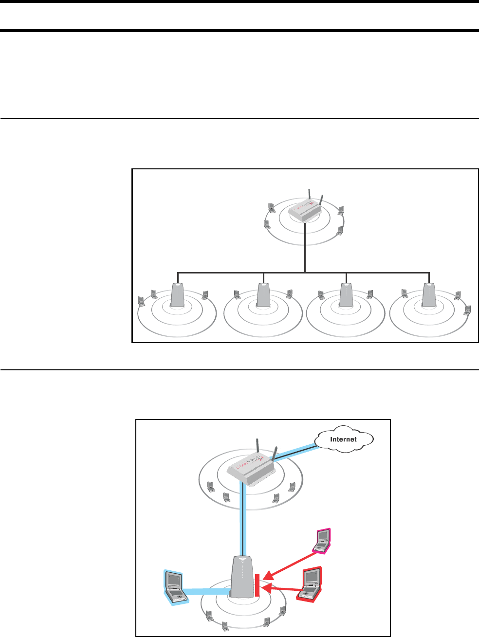
Scalable solution To service large locations or areas with many customers, you can deploy multiple
CN3200s or use CN300 satellite stations to extend the reach of the wireless
network.
Secure
infrastructure
The CN3200 and the CN300s provide the wireless cells which customers use to
connect their mobile computers. Intelligent bridging software on the CN300s
restricts customer traffic so that it can only flow to and from the CN3200.
Generally, the CN3200 is configured to provide a ‘public’ area on the network that
is freely available to customers without logging in. However, to gain access to the
Internet (or restricted resources on the local network) customers are usually
required to login. This secures the network and enables billing to take place.
P
U
B
L
I
C
W
L
A
N
P
U
B
L
I
C
W
L
A
N
P
U
B
L
I
C
W
L
A
N
P
U
B
L
I
C
W
L
A
N
P
U
B
L
I
C
W
L
A
N
CN3200
CN300CN300CN300 CN300
P
U
B
L
I
C
W
L
A
N
CN3200
P
U
B
L
I
C
W
L
A
N
Hacker
Unauthenticated
customer
Authenticated
customer
CN300
Chapter 1: Introduction 9
DRAFT
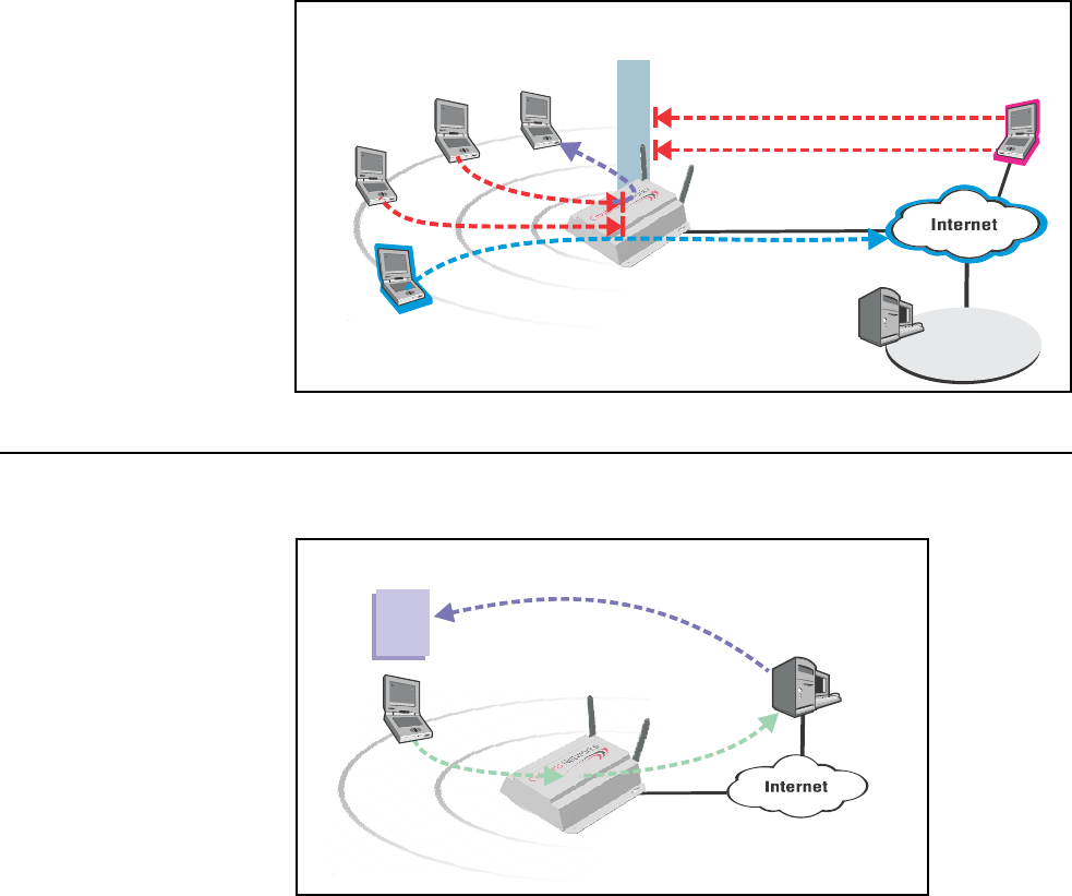
For added security, the CN3200 is protected from malicious Internet traffic by its
integrated firewall.
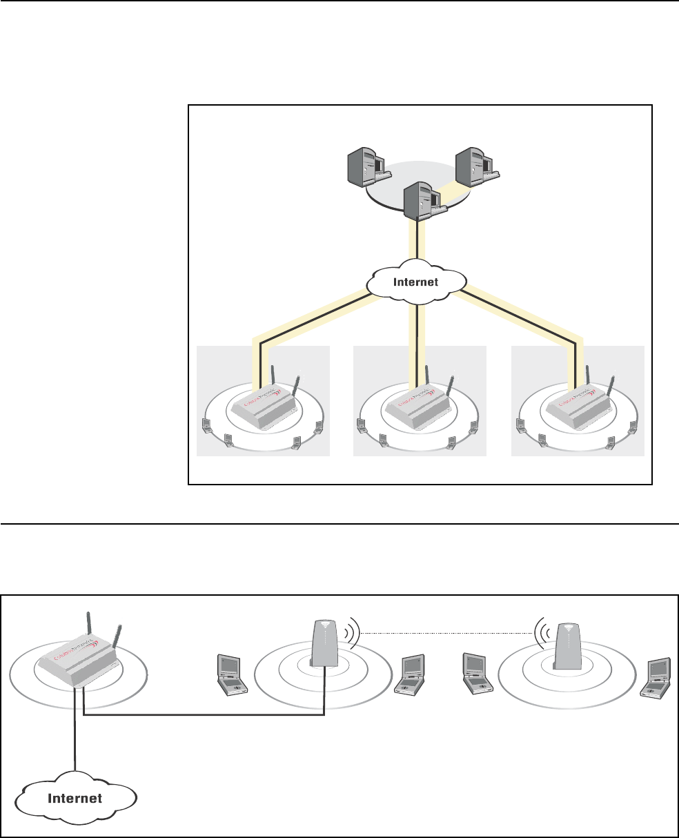
Enhanced user
experience
The CN3200 makes it easy to deliver a completely customized experience for
your customers.
At login time, customers are authenticated and their location within the network is
identified. This information is forwarded to an external web server, enabling it to
generate a custom experience for each location or even every customer.
Authenticated
Customer
Unauthenticated
Customer
syn attack
telnet
Integrated
Firewall
Hacker
Network
Operating Center
RADIUS
server
Stations cannot
exchange data
Customized
Web Page Custom page
is built based
on Customer ID
and location
Customer location and login
name are forwarded to web server Web server
Chapter 1: Introduction 10
DRAFT
Secure remote
management
Integrated VPN client software (PPTP and IPSec) enables the CN3200 to
establish a secure connection with a remote network operating center. This
provides a secure encrypted tunnel for management and accounting traffic,
enabling you to establish a centralized location from which to manage one or
more CN3200s.
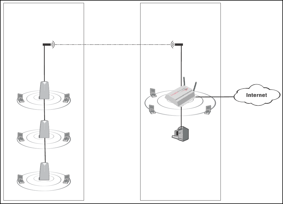
Wireless bridging The CN3200s wireless bridging feature enables you to use the wireless radio to
create point-to-point wireless links to other access points. This feature can be
used locally to extend the reach of a network without laying cable. For example:
Site #1 Site #2 Site #3
Secure tunnels protected
by IPSec or PPTP.
RADIUS
server
VPN
server
Management
station
Network
Operating
Center
CN3200
P
U
B
L
I
C
W
L
A
N
P
U
B
L
I
C
W
L
A
N
P
U
B
L
I
C
W
L
A
N
CN3200 CN3200
P
U
B
L
I
C
W
L
A
N
P
U
B
L
I
C
W
L
A
N
P
U
B
L
I
C
W
L
A
N
CN3200
Backbone LAN
CN300 CN300
wireless bridge
Chapter 1: Introduction 11
DRAFT
Or, it can be used to create point-to-point links over longer distances, such as
between two buildings (as illustrated below). This requires that the appropriate
external antenna be installed on each unit (not included).
P
U
B
L
I
C
W
L
A
N
CN3200
P
U
B
L
I
C
W
L
A
N
CN300
wireless bridge
P
U
B
L
I
C
W
L
A
N
CN300
P
U
B
L
I
C
W
L
A
N
CN300
antenna antenna
Building A Building B
RADIUS
server
Chapter 1: Introduction 12
DRAFT
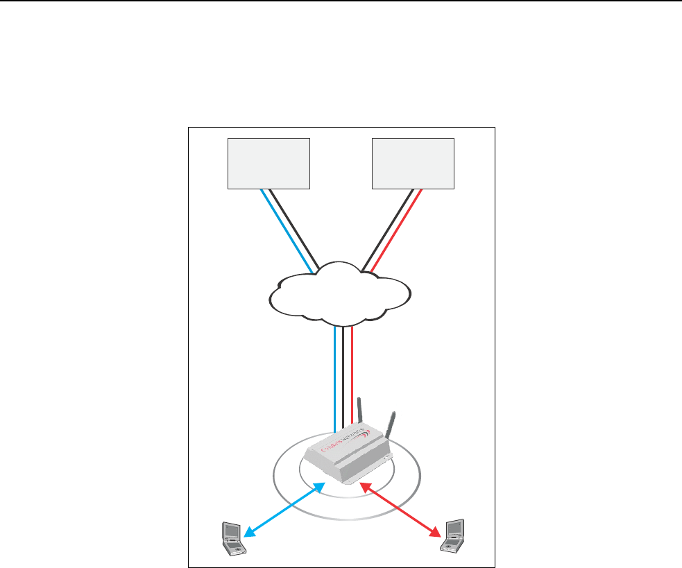
Multiple SSID
support
The CN3200 provides support for multiple SSIDs. This permits the wireless
network to be split into multiple distinct entities, each with its own SSID and
configuration settings.
By combining multiple SSIDs and IPSec VPNs, several WISPs (wireless Internet
service providers) can effectively share wireless access points in one or more
locations.
In this scenario, the CN3200 controls access to the Internet. However, it validates
customer logins and records accounting information using the RADIUS server in
each NOC. The CN3200 knows which RADIUS server to communicate with for a
particular customer based on the SSID the customer is associated with. IPSec
VPN tunnels provide full protection for all data transfers with the NOC.
Custom login pages can be hosted by each WISP, enabling the shared access
point to provide a distinct online experience for each WISP’s customers.
P
U
B
L
I
C
W
L
A
N
SSID #1
SSID #2
IPSec VPN #2
IPSec VPN #1
WISP #1
NOC
Internet
WISP #2
NOC
IPSec VPN #1 IPSec VPN #2

Chapter 1: Introduction 13
DRAFT
Feature summary
Wireless radio The CN3200’s dual-band mini-PCI radio module is software configurable to
operate either in the 2.4GHz band (802.11b and 802.11g) or the 5GHz band
(802.11a).
Note: Customers are responsible for verifying approval and to identify the
regulatory domain that corresponds to a particular country. Not all regulatory
domains have been approved. Please consult the Colubris Networks web site
(www.colubris.com/certifications) for an up-to-date list.
802.11a
The following features apply when the radio is operating as IEEE 802.11a (5 Ghz
Unlicensed ISM radio band).
Data rates
• 6, 9, 12, 18, 24, 36, 48, 54 Mbps
Frequency band
• North America: 5.150-5.350 GHz and 5.725 -5.825 GHz
• Europe: 5.150-5.350 GHz and 5.470-5.725 GHz and 5.725-5.825 GHz
• Japan: 5.150-5.250 GHz
Operating channels (non-overlapping)
• North America: 12
• Europe: 19
• Japan: 4
Modulation technique
Orthogonal Frequency Division Multiplexing (OFDM)
• BPSK @ 6 and 9 Mbps
• QPSK @ 12 and 18 Mbps
• 16-QAM @ 24 and 36 Mbps
• 64-QAM @ 48 and 54 Mbps
Media Access Protocol
• Carrier Sense Multiple Access with Collision Avoidance (CSMA/CA)
Receive sensitivity
• 6 Mbps: -85 dBm
• 54 Mbps: -65 dBm
Available Transmit Power Settings
• 6-24 Mbps: 17.5dBm +/- 2
• 54 Mbps: 12 dBm +/- 2
Note: Maximum power setting varies according to individual country regulations.
Standards compliance
Safety
• IEC 60950
• EN 60950

Chapter 1: Introduction 14
DRAFT
Radio Approvals
•Wi-Fi
• FCC Part 15.401-15.407
• RSS-210 (Canada)
• EN 300 440 (Europe)
• ARIB STD-T71 (Japan)
EMI and Susceptibility (Class B)
• FCC Part 15.107 and 15.109
• ICES-003 (Canada)
• VCCI (Japan)
• EN 301.489-1 and -17 (Europe)
Other
• IEEE 802.11a
• FCC Bulletin OET-65C
• RSS-102
IEEE 802.11h Support
• Dynamic Frequency Selection (DFS) and Transmit Power Control (TPC) are
supported as per the current draft of the IEEE 802.11h specification
Antenna
Two SMA (Female) connectors for use with external antenna (sold separately).
Security architecture client authentication
• SSL protected WEB-based Authentication
• 802.1X support including: PEAP, EAP-TLS, EAP-TTLS, and EAP-SIM to yield
mutual authentication
• Wi-Fi Protected Access (WPA) with AES support in HW (ready for WPA-2)·
Support for static and dynamic IEEE 802.11 WEP keys of 40 bits and 128 bits
802.11b/g
The following features apply when the radio is operating as IEEE 802.11b and
802.11g (2.4 Ghz Unlicensed ISM radio band).
Data rates
• IEEE 802.11b: 1, 2, 5.5, and 11 Mbps
• IEEE 802.11g (OFDM only): 6, 9, 12, 18, 24, 36, 48, 54Mbps
Frequency band
• North America: 2.412 to 2.462 GHz
• Europe: 2.412 to 2.472 GHz
• Japan: 2.412 to 2.484 GHz
Operating channels
• North America/China: 1
• Europe: 13
• Japan: 14
Non-overlapping operating channels
• Worldwide: 3
Chapter 1: Introduction 15
DRAFT
Modulation technique
IEEE 802.11b: Direct sequence spread spectrum (DSSS)
• DBPSK @ 1 Mbps
• DQPSK @ 2 Mbps
• CCK @ 5.5 and 11 Mbps
IEEE 802.11g: Orthogonal Frequency Division Multiplexing (OFDM)
• BPSK @ 6 and 9 Mbps
• QPSK @ 12 and 18 Mbps
• 16-QAM @ 24 and 36 Mbps
• 64-QAM @ 48 and 54 Mbps
Media Access Protocol
• Carrier Sense Multiple Access with Collision Avoidance (CSMA/CA)
Receive sensitivity
IEEE 802.11b
• 11 Mbps: -86 dBm
IEEE 802.11g:
• 6 Mbps: -85 dBm
• 54 Mbps: -65 dBm
Available Transmit Power Settings
IEEE 802.11b
• 1-11 Mbps: 18 dBm +/- 2
IEEE 802.11g:
• 6-24 Mbps: 17 dBm +/- 2
• 54 Mbps: 11.5 dBm +/- 2
Note: Maximum power setting varies according to individual country regulations.
Standards compliance
Safety
• IEC 60950
• EN 60950
Radio Approvals
•Wi-Fi
• FCC Part 15.247
• RSS-139-1, RSS-210 (Canada)
• EN 300.328 (Europe)
• TELEC 33B (Japan)
EMI and Susceptibility (Class B)
• FCC Part 15.107 and 15.109
• ICES-003 (Canada)
• VCCI (Japan)
• EN 301.489-1 and -17 (Europe)
Other
• IEEE 802.11a
• FCC Bulletin OET-65C
• RSS-102

Chapter 1: Introduction 16
DRAFT
Antenna
Two SMA (Female) connectors for use with external antenna (sold separately).
Security architecture client authentication
• SSL protected WEB-based Authentication
• 802.1x support including: PEAP, EAP-TLS, EAP-TTLS, and EAP-SIM to yield
mutual authentication
• Wi-Fi Protected Access (WPA) with AES support in HW (ready for WPA-2)·
Support for static and dynamic IEEE 802.11 WEP keys of 40 bits and 128 bits
Hardware Status LEDs
Provide status of wireless port, LAN ports, and power
Uplink ports
Two auto-sensing 802.3 10/100BASE-T Ethernet ports
Memory
• 32 Mbytes RAM
• 16 Mbytes FLASH
Input power requirements
• 90 to 240 VAC +/- 10% (power supply)
• IEEE 802.3af 48 VDC +/- 10%(device)
Power draw
8 watts
Dimensions
• Length: 165.7 mm
• Width: 162.5 mm
• Height: 48 mm
Temperature range
• Operating: 0°C to 60°C
• Storage: -40°C to 70°C
Humidity
5% to 95% typical (non-condensing)
Warranty
One year
Networking • IEEE 802.1d compliant bridging
• GRE (RFC 2784)
• DHCP Server (RFC 2131)
• DHCP Client
• DHCP Relay
• DHCP Option 82 (RFC 3046)
• PPPoE Client (RFC 2516)
• DNS Relay
• Static IP Routing
• Network Address Translation (RFC 1631)
• One-to-one NAT for VPN support

Chapter 1: Introduction 17
DRAFT
• RIP v1 (RFC 1058) and v2 (RFC 1723)
• SMTP (e-mail) redirection
• ICMP (RFC 792)
• ARP (RFC 826)
• CIDR (RFC 1519)
Network
management
• SNMP v1 and v2
• MIB-II with TRAPS
• Colubris Hot Spot MIB for user session control and downstream AP
management
• RADIUS Authentication MIB (RFC 2618)
• RIP v2 extension MIB (RFC 1724)
• Secure access (SSL and VPN) to embedded HTML Management Tool
• Scheduled configuration and firmware upgrades from central server
• Real-time status, information and protocol traces (layer 2 and 3)
Access controller
functions
• Secure HTML login page
• Support for centralized WEB Portal
• WEB-Proxy server
• Fixed-IP address spoofing
• Location-aware user authentication
• Support for 802.1x using EAP-SIM, EAP-TLS, EAP-TTLS and PEAP
• MAC-level authentication for non-HTTP or 802.1x devices
• RADIUS AAA using EAP-MD5, PAP, CHAP, MSCHAP v2
• Provides detailed accounting based on session duration and/or volume of data
• Flexible support for pre-paid subscription
• Support up to 100 concurrent users at location
Security • RADIUS Client (RFC 2865 and 2866)
• Layer-2 Wireless Isolation
• Integrated VPN client (IPSec or PPTP) for secure connection to central
RADIUS Server
• Per-user customizable firewall
RF Tools • Rogue AP detection
• Embedded Site Survey tools
Compatibility • Communicates with all Wi-Fi certified wireless adapters
• Supports all operating systems

Chapter 1: Introduction 18
DRAFT
Authentication and
accounting
• Secure HTML login page
• Support for 802.1x using EAP-MD5, EAP-TLS, EAP-TTLS, PEAP
• RADIUS AAA supporting EAP-MD5, PAP, CHAP, MSCHAP v2, MSCHAP v1
• MAC-level authentication for non-HTTP devices
• Supports up to 100 concurrent users
• Provides accounting by time used or data transferred/received by customers
• Traffic quotas
Management • Web-based management tool
• Secure local and remote management via HTTPS and VPN
• Scheduled configuration upgrades from a central server
• Remote Syslog
• Web-based firmware upgrades
• Real-time status and information protocol traces
• Site survey and monitoring tool
• SNMP V1, V2 MIB-II with traps and Colubris MIB
• RADIUS Authentication Client MIB (RFC 2618)
Interfaces • IEEE 802.11b wireless port
• 10/100BaseTX Ethernet port
• 10BaseT Ethernet port
Operating
Environment
• Temperature: 0ºC to 55ºC
• Humidity: 15% to 95% non-condensing
Regulatory
Approvals
• FCC Part 15, CSA NRTL (C22.2 No 950, UL 1950)
• CE Mark (EN55022, EN55024, IEC 60950)
• Wi-Fi Certified
Chapter 1: Introduction 19
DRAFT
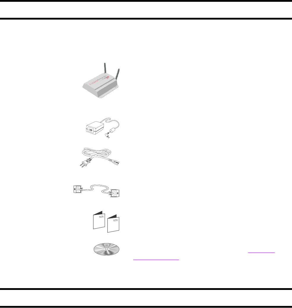
Package contents
Make sure that your package contains the following items. If an item is missing,
contact your reseller.
Technical support
To obtain technical support, contact your reseller.
Information about Colubris Networks products and services, including
documentation and software updates, is available on our web site at
www.colubris.com.
CN3200 Wireless Access Controller
Power supply (optional)
Power cord (optional)
CD-ROM
Cross-over Ethernet cable (yellow)
CN3200 warranty, license, and registration cards
Contains the CN3200 Administrator’s Guide, Colubris
Backend Archive, and the Colubris Enterprise MIB.

Chapter 1: Introduction 20
DRAFT
Syntax conventions
This manual uses the following formatting conventions.
Example Description
Network When referring to the management tool
web interface, items in bold type identify
menu commands or input fields. They are
presented exactly as they appear on
screen.
Network > Ports When referring to the management tool
web interface, submenus are indicated
using the ‘>’ sign. The example refers to
the Ports submenu, which is found under
the Network menu.
ip_address Items in italics are parameters that you
must supply a value for.
use-access-list=usename Monospaced text is used to present
command line output, program listings, or
commands that are entered into
configuration files or profiles.
ssl-certificate=URL [%s] [%n] Items enclosed in square brackets are
optional. You can either include them or
not. Do not type the brackets.

Chapter 2: Important concepts 21
DRAFT
Chapter 2: Important concepts
Chapter 2
Important concepts
This chapter covers important topics that will help to understand how
to install, deploy, and manage a wireless public access network.
Chapter 2: Important concepts 22
DRAFT
Networking areas
Wireless cells Each wireless networking area is created by installing a CN3200, and if needed,
one or more CN300s. For example:
Coverage
As a starting point for planning your setup, you can assume that the CN3200
provides a wireless cell of up to 300 feet (100 meters) in diameter at high power.
Before creating a permanent installation, you should always perform a live test of
the coverage provided by each access point to determine its optimum settings
and location.
Coverage provided by an access point will be affected by all of the following
factors.
Transmission power of the radio
More power means better signal quality and bigger wireless cells. However, cell
size should generally not exceed the range of transmission supported by your
client stations. If it does, client stations will be able to receive signals from the
access point, but they will not be able to reply. Another limiting factor is proximity
of other access points in a multi-cell setup. In this case signal strength should be
adjusted to avoid interference between adjacent cells.
Note: Governmental regulations in different parts of the world determine the
maximum power output of the CN3200’s radio.
Antenna configuration
Antennas play a large roll in determining shape of the wireless cell and
transmission distance. Internal antennas are general omni-directional and
provide the same type of coverage in all directions around the access point.
Consult the specifications for the antenna to determine how it affects wireless
coverage.
Interference
Another limiting factor is interference from other access points or devices that
operate in the same frequency band.
Protected network resources
P
U
B
L
I
C
W
L
A
N
P
U
B
L
I
C
W
L
A
N
CN300CN300
P
U
B
L
I
C
W
L
A
N

Chapter 2: Important concepts 23
DRAFT
Access points operating in the 2.4 Ghz band may experience interference from
2.4 Ghz cordless phones and microwave ovens.
Physical characteristics of the location
To maximize coverage of the wireless cell, the wireless access points are best
installed in an open area with as few obstructions as possible. Try to choose a
location that is central to the area being served.
Radio waves cannot penetrate metal, instead they are reflected. This means that
the wireless access points are able to transmit through wood or plaster walls, and
closed windows. However, the steel reinforcing found in concrete walls and floors
may block transmissions, or reduce signal quality by creating reflections. This
can make it difficult for a single unit to serve users on different floors in a concrete
building. Such installations will require a separate wireless access points on each
floor.
Authentication and accounting
The CN3200 provides user authentication and accounting support for the
wireless customers and manages the security of the network. This means
ensuring that only authorized traffic is permitted to reach the protected network
resources.
Multiple SSIDs
The CN3200 supports the creation of multiple virtual wireless networks, all
sharing the same wireless port. Each virtual network has its own SSID, MAC
address, and configuration settings.
Security
To preserve network security, the CN3200 and the CN300 block all
communications between wireless client stations. If required, you can disable this
feature.
Protected network resources
All resources connected to the CN3200’s Internet port are protected. This means
that access to them is controlled by configuration settings on the CN3200. By
default, these settings are:
•unauthenticated customers cannot access any protected network resources
•authenticated customers can access all protected network resources
While this type of configuration may be suitable for a simple wireless hotspot that
provides access to the Internet, more complex setups will need more fine-grained
control of the protected network resources. To support this, the CN3200 provides
a fully-configurable access list mechanism, which has the following benefits:
•The ability to make specific protected resources available to unauthenticated
users. For example, when you want to have public web pages available to
customers before they log in, but locate the web server on a protected network.
•The ability to define a list of accessible resources for a single customer or a an
entire group. For example, if you have several customer groups (teachers,
students, visitors), each can be given access to specific network resources.
•The ability to block specific addresses for a single customer or entire group. For
example, you could disallow traffic to file swapping Internet sites to cut down on
bandwidth usage.

Chapter 2: Important concepts 24
DRAFT
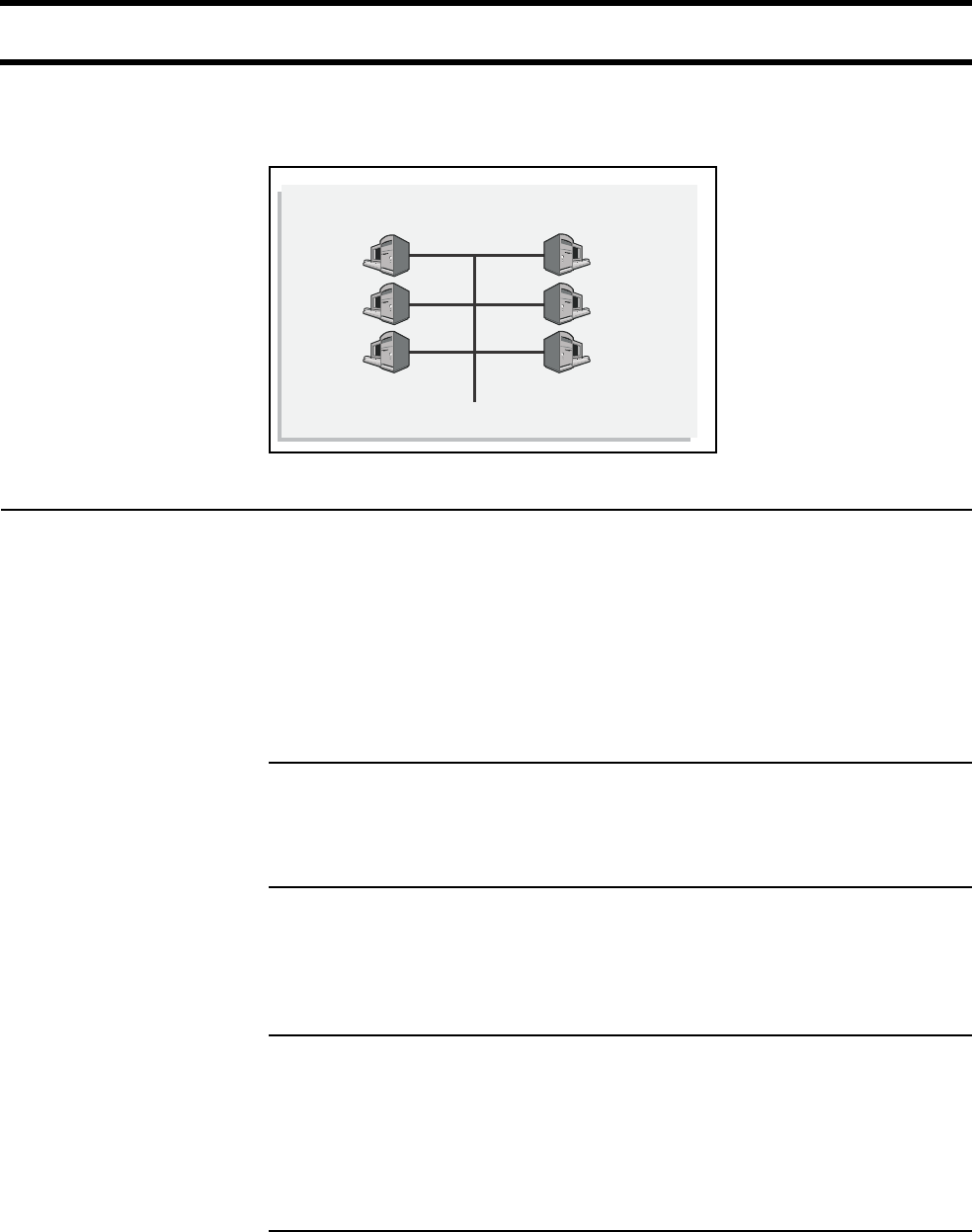
Attaching to a wired
LAN
The CN3200 can be attached to a wired LAN. Computers on an attached wired
LAN are treated just like those on the wireless LAN. Each computer must be
authenticated before it can gain access to protected network resources.
To maintain network security, the wireless LAN and wired LAN are distinct. Traffic
is not forwarded between them.
Chapter 2: Important concepts 25
DRAFT
Network operating center (NOC)
The NOC is where the RADIUS, Web, SMTP, FTP, DHCP, DNS, VPN servers and
the management station are installed.
NOC components RADIUS server
The RADIUS server is used to authenticate customers when they log onto the
network and record accounting information for each session. It is also used to
store configuration settings for the CN3200 and customers. Before the CN3200
activates the public network, it must authenticate itself to the RADIUS server and
retrieve its configuration information.
The CN3200 is compliant with RFC 2865 and RFC 2866 and will work with a
variety of RADIUS servers.
Web/FTP server
If you intend to customize the look and feel of the public access interface, you will
need a Web or FTP server to store your customized pages.
SMTP server
The CN3200 provides an e-mail redirection feature which enables customers to
send e-mail using a SMTP server that you supply. If you intend to support this
feature, you must install an SMTP server to handle redirected outgoing mail.
VPN server
The CN3200 can use its integrated VPN client (PPTP, IPSec) to create an
encrypted connection to a VPN server. This is useful if the CN3200 is connected
to a NOC via the Internet. The tunnel ensures the security of authentication traffic
and remote management activities and enables you to manage all your CN3200s
from a single remote site without security concerns.
DNS/DHCP server
The CN3200 can be configured to relay DHCP requests to an external server.
This enables you to control address allocation for all wireless cells from a central
location.
VPN
server
RADIUS
server
Web/FTP
server
SMTP
server
Management
station
DNS/DHCP
server
Network Operating Center

Chapter 2: Important concepts 26
DRAFT
Management station
This station is used to control and configure the CN3200 and any satellite
CN300s. Control can occur via an SNMP console or through the CN3200’s web-
based management tool.
Sending traffic to
the NOC
For secure transmission of traffic between the CN3200 and the NOC, the
CN3200 features both PPTP and IPSec clients. Chapter 10 explains how to
configure secure remote connections.

Chapter 2: Important concepts 27
DRAFT
The public access interface
The public access interface is the sequence of web pages that customers use to
login to the wireless network and to manage their accounts.
The CN3200 ships with a default public access interface that you can customize
to meet the needs of your installation. However, before you do this, you should
initialize the default setup and test it with your network as described in Chapter 9.
Once the default interface is working, you can make changes to it as described in
Chapter 15.
Important: The CN3200 public access interface is not functional until the
CN3200 can successfully connect to a RADIUS server and authenticate itself.
This means that the login page for the public access interface will appear, but
customers will get an error when they try to log in. This occurs regardless of the
method you are using to authenticate customers.
Important: Customers using PDAs that only support a single browser window
will have difficulty using the public access interface in its standard configuration.
To solve this problem, see “Supporting PDAs” on page 172.

Chapter 2: Important concepts 28
DRAFT
Connecting to and using the wireless network
In order to access protected network resources, customers must:
• successfully connect to the wireless network
• open the login page in their web browser and supply a valid username and
password OR login with an 802.1x or WPA client (if this feature is enabled on
the CN3200)
The CN3200 provides several features that make it easy for customers to
accomplish these tasks.
Broadcast IP
address
This feature enables the CN3200 to broadcast its wireless network name (SSID)
to all client stations. Most wireless adapter cards have a setting that enables
them to automatically discover access points that broadcast their names and
automatically connect to the one with the strongest signal.
This feature is enabled by default. To disable it go to the Network > Wireless
page in the CN3200 management tool. If you disable this feature, customers
must manually specify the SSID you define for the wireless network.
Allow any IP
address
This feature enables the CN3200 to connect with wireless client stations that are
using a static IP address that is not on the same segment as the wireless
network. This permits customers to access the wireless network without
reconfiguring their network settings.
For example, by default the CN3200 assigns creates the wireless network on the
subnet 192.168.1.0. If a client station is pre-configured with the address
10.10.4.99, it will still be able to connect to the CN3200 without changing its
address, or settings for DNS server and default gateway.
This feature is enabled by default. To disable it go to the Security >
Authentication > Advanced Settings page in the CN3200 management tool.
WPA/802.1x clients The CN3200 provides complete support for these clients. User accounts are
managed remotely on a RADIUS server.
Proxy server
support
This feature enables the CN3200 to support client stations that are configured to
use a proxy server for HTTP and HTTPS, without requiring customers to
reconfigure their systems.
This feature is disabled by default. To enable it, go to the Client station settings
box on the Security > Authentication > Advanced Settings page.
For this feature to work, client stations:
• must not be using a proxy server on port 21, 23, 25, 110, 443, 8080, or 8090.
To support ports 8080 and 8090 change the settings for Security >
Authentication > Advanced Settings > Access controller ports.
• must be using the same proxy server address and port number for both HTTP
and HTTPS.
• must not be using 802.1x.
Enabling this feature reduces the maximum number of supported wireless
customers to 50.

Chapter 2: Important concepts 29
DRAFT
The RADIUS server
Main tasks The RADIUS server is a key component of the public access infrastructure. It is
used to perform a variety of tasks, including:
• authenticating the CN3200
• authenticating administrator logins
• authenticating customer logins
• storing accounting information for each customer
• storing customization information for the public access interface
Authenticating the CN3200 and storing config information
The CN3200 authenticates itself to a RADIUS server each time:
• it is powered up
• it is restarted
• the authentication interval expires (configured via the management tool)
At each authentication, the following configuration information is retrieved if
defined in the RADIUS profile for the CN3200:
• Access list defining the resources unauthenticated customers can access.
• URLs specifying the location of customized Web pages and supporting files.
• A URL specifying the location of a custom security certificate.
• A URL specifying the location of a configuration file.
• The MAC addresses of devices to authenticate.
• The default idle timeout for customer sessions.
• The default address for the SMTP redirection
When you set up a profile for the CN3200 on the RADIUS server you define this
information in the form of a Colubris Networks vendor-specific attribute. For
details see page 214.
Authenticating customers and storing accounting information
See page 30 for details.
Authenticating administrator logins
The RADIUS server can also be used to authenticate administrator logins. This
enables you to have multiple administrators, each with their own username and
password, instead of the single account controlled on the Management >
Management tool page.
More information For information on configuring the RADIUS server, see:
•Chapter 16, which explains all the settings you can define on the RADIUS
server for your customer accounts and network operation.
•Chapter 18, which provides a walkthrough of a sample RADIUS configuration
using Steel-belted Radius.
•Chapter 19, which provides a walkthrough of a sample RADIUS configuration
using Microsoft's RADIUS server: Internet Authentication Service.

Chapter 2: Important concepts 30
DRAFT
Customer authentication
This manual uses the term customer to refer to any person or device that logs
into the public access network created by the CN3200.
Customers can be authenticated in several ways.
RADIUS server This method enables you to use the services of a RADIUS server to manage
your customers, track and manage connection time, and generate billing
information.
Once the customer is authenticated, configuration information is retrieved for the
customer. This includes settings for:
• Connection time limit for the customer’s session.
• Idle time limit for the customer’s session.
• Access list for the customer.
• Address of the e-mail server to use for redirection of the customer’s e-mail.
• URLs specifying the location of customized Welcome and Goodbye pages for
the customer.
When you define a profile for each customer on the RADIUS server you define
this information in the form of regular RADIUS attributes and a Colubris Network
vendor-specific attribute. See “Creating customer profiles on the RADIUS server”
on page 225 for more information.
Local user list The CN3200 enables you to create local accounts that bypass RADIUS
authentication and accounting. To login, customers use the public access
interface, but instead of using the RADIUS server, authentication is handled
directly by the CN3200 and no RADIUS accounting information is logged. These
accounts are useful for system administrators and management personnel.
Note: Local users can must use HTML to login. WPA/802.1x users must be
authenticated via RADIUS.
To setup these accounts, login to the management tool and open the Security >
User List page.
MAC-based
authentication
The CN3200 can authenticate devices based on their MAC address. This is
useful for authenticating devices that do not have a web browser (cash registers,
for example). These devices do not log in through the public access interface,
rather, as soon as the CN3200 sees their MAC address appear on the network,
the CN3200 attempts to authenticate them. To setup these accounts, see page
223.
WPA/802.1x The CN3200 provides full support for users with 802.1x or WPA client software.
The CN3200 terminates the session and authenticates users via an external
RADIUS server or by using preshared keys (WPA only).
The CN3200 supports 802.1x client software that uses EAP-TLS, EAP-TTLS,
and PEAP. Dynamic key rotation is supported.

Chapter 3: Planning your installation 31
DRAFT
Chapter 3: Planning your installation
Chapter 3
Planning your installation
This chapter provides sample deployment strategies for two common
scenarios. These scenarios will give you a good idea on how to approach
your installation.
Chapter 3: Planning your installation 32
DRAFT
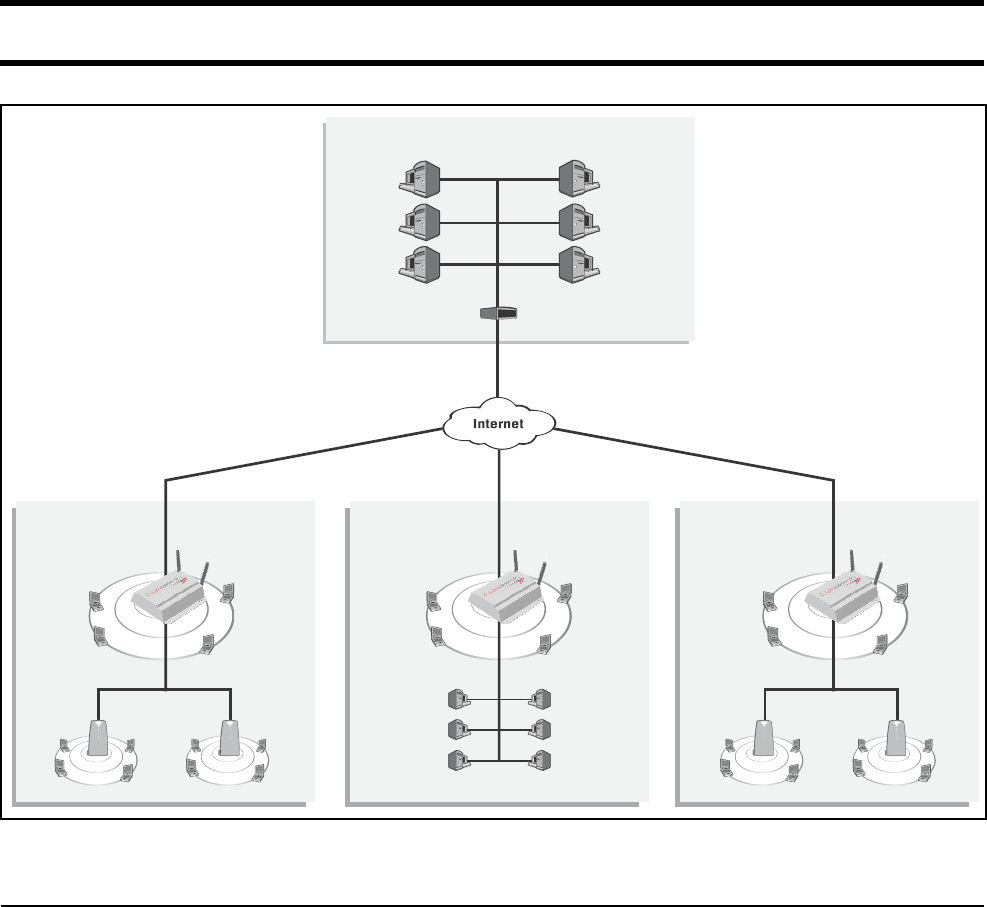
Multi-site installation
About this
installation
• A single CN3200 is installed along with one or more CN300 satellites at sites
#1 and #3.
• At site #2, the CN3200 provides a wireless network and is also connected to a
LAN to enable a number of wired computers to act as public access stations.
• Each CN3200 is connected to the Internet via a broadband modem. The
Internet connection is protected by the CN3200’s firewall.
• A VPN connection is established between each CN3200 and the VPN server at
the NOC. This protects all management traffic exchanged between the
CN3200s and the NOC, which includes:
• RADIUS authentication and accounting data.
• Management session used to control CN3200 configuration and firmware
updates.
• Centralized management of customer profiles on the RADIUS server enables
customers to login at any location.
VPN
server
RADIUS
server
Web/FTP
server
SMTP
server
Management
station
DNS/DHCP
server
Network Operating Center
Site #1 Site #2 Site #3
Router/Firewall
CN3200
CN300 CN300CN300 CN300
P
U
B
L
I
C
W
L
A
N
P
U
B
L
I
C
W
L
A
N
P
U
B
L
I
C
W
L
A
N
P
U
B
L
I
C
W
L
A
N
P
U
B
L
I
C
W
L
A
N
CN3200
P
U
B
L
I
C
W
L
A
N
CN3200
P
U
B
L
I
C
W
L
A
N

Chapter 3: Planning your installation 33
DRAFT
Installation strategy General configuration tasks
Site #1 and #3
Site #2
Step Description See
1 Setup and configure profiles on the RADIUS server(s). Pages 213 to 232
2 Create custom web pages for the public access
interface. (optional)
Chapter 15
3 Create custom certificates. (optional) Chapter 14
Step Description See
1 Setup the CN3200. Chapter 4
2 Establish a connection to the management tool. Pages 44 and 46
3 Define management tool security settings. Page 49
4 Configure and deploy the multi-cell wireless network
with the CN300s.
Chapter 6
5 Configure the Internet connection and firewall. Chapter 8
6 Start the public access interface. Chapter 9
7 Configure a VPN connection to the NOC. Chapter 10
Step Description See
1 Setup the CN3200. Chapter 4
2 Establish a connection to the management tool. Pages 44 and 46
3 Define management tool security settings. Page 49
4 Configure the wireless network. Chapter 6
5 Connect the CN3200 to the local wired LAN. Chapter 7
6 Configure the Internet connection and firewall. Chapter 8
7 Start the public access interface. Chapter 9
8 Configure a VPN connection to the NOC. Chapter 10
Chapter 3: Planning your installation 34
DRAFT
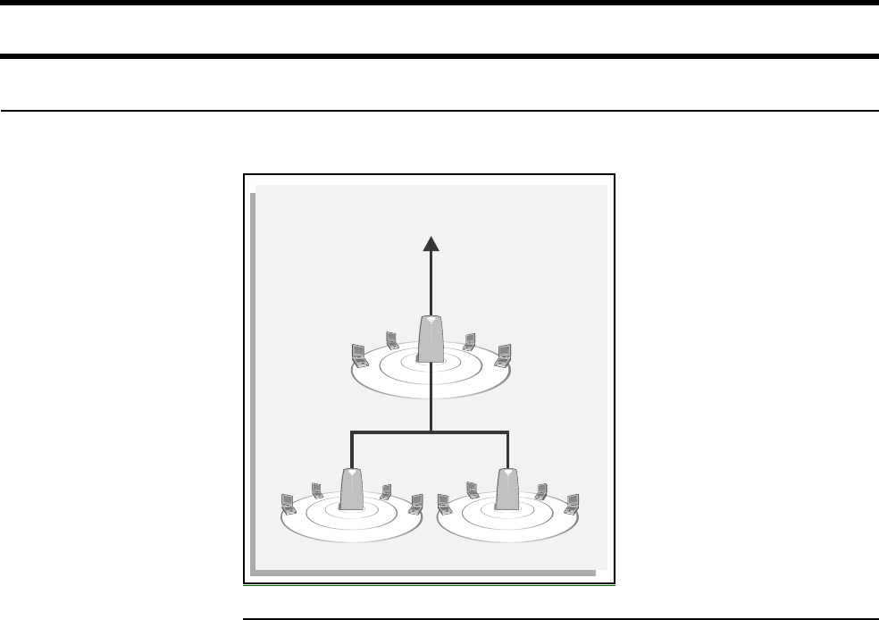
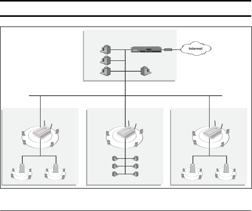
Multi-area installation
About this
installation
• A single CN3200 is installed along with one or more CN300 satellites at areas
#1 and #3.
• At area #2, the CN3200 provides a wireless network and is also connected to a
LAN to enable a number of wired computers to act as public access stations.
• Each CN3200 is connected to the NOC via the backbone LAN.
• Centralized management of customer profiles on the RADIUS server enables
customers to login to the wireless network in any area.
Backbone LAN
Area #1 Area #2 Area #3
RADIUS
server
Web/FTP
server
SMTP
server
Management
station
Network Operating Center
12345678
HDD PWR
Reset
GPIO
CN1500
modem
CN300CN300
P
U
B
L
I
C
W
L
A
N
P
U
B
L
I
C
W
L
A
N
CN3200
P
U
B
L
I
C
W
L
A
N
CN300CN300
P
U
B
L
I
C
W
L
A
N
P
U
B
L
I
C
W
L
A
N
CN3200
P
U
B
L
I
C
W
L
A
N
CN3200
P
U
B
L
I
C
W
L
A
N

Chapter 3: Planning your installation 35
DRAFT
Installation strategy General configuration tasks
Area #1 and #3
Area #2
Step Description See
1 Setup and configure profiles on the RADIUS server(s). Pages 213 to 232
2 Create custom web pages for the public access
interface. (optional)
Chapter 15
3 Create and install a custom certificate (optional). Chapter 14
Step Description See
1 Install the CN3200. Chapter 4
2 Establish a connection to the management tool. Pages 44 and 46
3 Define management tool security settings. Page 49
4 Configure and deploy the multi-cell wireless network
with the CN300s.
Chapter 6
5 Connect the Internet port to the backbone LAN and
configure IP addressing.
Page 79
6 Start the public access interface. Chapter 9
Step Description See
1 Install the CN3200. Chapter 4
2 Establish a connection to the management tool. Pages 44 and 46
3 Define management tool security settings. Page 49
4 Configure the wireless network. Chapter 6
5 Connect the CN3200 to the local wired LAN. Chapter 7
6 Connect the Internet port to the backbone LAN and
configure IP addressing.
Page 79
7 Start the public access interface. Chapter 9
Chapter 3: Planning your installation 36
DRAFT

Chapter 4: Installation 37
DRAFT
Chapter 4: Installation
Chapter 4
Installation
This chapter provides an overview of the CN3200 hardware and explains
how to install it.
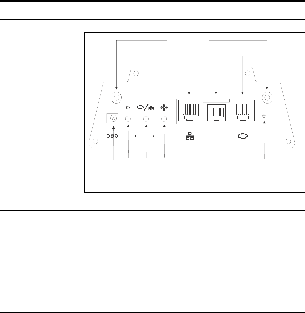
Chapter 4: Installation 38
DRAFT
Anatomy
Antenna
connectors
The CN3200 has two antenna connectors. Both can transmit and receive. If a
single antenna is used it can be attached to either connector.
The connectors are SMA male with reverse polarity. This means antennas or cable
connectors must be SMA female with reverse polarity. Antennas should be 2 dBi or less
and can be either directly attached or attached via a coax cable.
Antenna diversity
The CN3200 supports antenna diversity. One benefit of this feature is that for a
given client station connection, the CN3200 always transmits on the antenna it
receives.
If transmission fails, the CN3200 automatically switches antennas and retries.
Ports The CN3200 has three ports:
LAN port
The CN3200 has two antenna connectors. Both can transmit and receive. If a
single antenna is used it can be attached to either connector. The connectors are
SMA male with reverse polarity. This means antennas or cable connectors must
be SMA female with reverse polarity. Antennas should be 2 dBi or less and can
be either directly attached or attached via a coax cable.
Serial port
For future use. Do not connect this port to telecommunications equipment or a phone line.
Internet port
10/100 mbps Ethernet port with RJ-45 connector. Do not connect this port directly to a
metropolitan area network (MAN) or wide area network (WAN).
Antenna Connectors
Reset button
LAN port Internet port
Power
light
Wireless
light
Ethernet
light
Power
connector
Serial port

Chapter 4: Installation 39
DRAFT
Powering the
CN3200
There are two ways to power the CN3200: DC adapter or PoE.
DC power adapter
The supplied DC power adaptor provides 2A at 5V.
Important: The power adapter is not rated for use in plenum installations.
Power over Ethernet (PoE)
The CN3200 supports PoE on the LAN port and can be used with any IEEE
802.3af-compliant power injector.
Important: Cisco PoE injectors are not compliant with IEEE 802.3af and cannot
be used with the CN3200.
Status lights The status lights provide the following operational information.
Power
on The CN3200 is fully operational.
flashing The CN3200 is starting up.
off Power is off.
Ethernet
on LED comes on for a short period when the link is established.
flashing Indicates that either port is transmitting or receiving.
off Ports are not connected or there is no activity.
Wireless
flashing Wireless port is receiving data.
Startup behavior
When power is applied to the CN3200, the power light will start flashing. When
the power light stops flashing, initialization is complete and the CN3200 is fully
operational.
Radio The CN3200 provides support for IEEE 802.11a and 802.11b/g technologies in a
single radio which can be configured in real-time for complete flexibility of
operation.
• When operating in 802.11a mode, the radio supports data rates of up to 54
Mbps and eight non-overlapping channels.
• When operating in 802.11b/g mode, the radio provides data rates up to 54
Mbps and three non-overlapping channels to support both 802.11b and
802.11/g client stations.

Chapter 4: Installation 40
DRAFT
Reset button The reset button is located on the rear of the CN3200. Use the end of a paper
clip or another pointy object to press the button.
Restarting
Press and release the button quickly to restart the CN3200. This is equivalent to
disconnecting and reconnecting the power. The CN3200 will restart immediately.
Resetting to factory defaults
To reset the CN3200 to its factory default settings, do the following:
1. Press and hold the reset button. All the lights on the CN3200 front panel will
light up.
2. When the lights begin to flash (after about five seconds), immediately release
the button.
3. The CN3200 will restart with factory default settings. When the power light
stops flashing, the CN3200 is fully operational.
Important: Resetting the CN3200 deletes all your configuration settings, resets
the Administrator username and password to ‘admin’, and sets the Wireless port
IP address to 192.168.1.1 and the LAN port IP address 192.168.4.1.
The management tool can also be used to reset the CN3200 to its factory
defaults. See “Configuration management” on page 53 for details.

Chapter 4: Installation 41
DRAFT
Installing the CN3200
Important: Installation must be performed by a professional installer familiar with
local regulations governing wireless devices.
Mounting the
CN3200
When mounting the CN3200 on a wall, ceiling or other surface, make sure that:
• the surface you attach the CN3200 to and the fasteners you use are able to
support at least 5.1 kg (11.25 pounds)
• cable pull (accidental or otherwise), must not make the unit exceed the 5.1 kg
(11.25 pound) limit
Plenum installations
Plenum rated cables and attachment hardware must be used if the CN3200 is
installed in a plenum. Since the power adapter is not rated for plenum
installations, only the CN3200 and appropriate cabling can be located in the
plenum.
Note: If Colubris Networks supplied PoE injectors are used in a plenum
installation, they must be located outside the plenum.
Configuring the
CN3200
Before attaching the CN3200 to your network, it is recommended that you start
the management tool and define basic configuration settings as described in
Chapter 5.
By default, the CN3200 is configured to operate as a DHCP server with a
network address of 192.168.1.1 on the wireless and 192.168.4.1 on the LAN
port.
The Internet port is configured to operate as a DCHP client.
Refer to Chapter 7 for complete instructions on how to attach the CN3200 to your
network.
Chapter 4: Installation 42
DRAFT

Chapter 5: The management tool 43
Chapter 5: The management tool
Chapter 5
The management tool
This chapter provides an overview of the Web-based management tool
and explains how to use it to perform management and configuration
tasks.

Chapter 5: The management tool 44
Overview
The management tool is a Web-based interface to the CN3200 that provides
easy access to all configuration functions.
Important: Only one administrator can be logged into the management tool at a
given time. If a second administrator logs in while the first is connected, the first
administrator is logged out.
Management
station
The management station is the computer that you use to connect to the
management tool. To act as a management station, a computer must:
• have a JavaScript-enabled Web browser installed (Netscape 4.04 or higher, or
Internet Explorer 5.0 or higher).
• be able to establish an IP connection with the CN3200
Configuring the management station for wireless access
Install and configure the wireless adapter in the management station according
to the directions that came with it. During installation make sure that:
•encryption is disabled
•TCP/IP is installed and configured. IP addressing can be either static or DHCP.
A unique feature of the CN3500 is its ability to support connections from client
stations that have a preconfigured static IP address.
•Set the SSID to be “Colubris Networks”.
Configuring the management station for wired access
Install and configure a network adapter in the management station according to
the directions that came with it. During installation make sure that:
• TCP/IP is installed and configured. IP addressing can be either static or DHCP.
A unique feature of the CN3500 is its ability to support connections from client
stations that have a preconfigured static IP address.
Management
scenarios
The CN3200 can be managed both locally and remotely for complete flexibility.
The following management scenarios are supported:
Local Management
Remote management
Default settings The following are some important default settings
Wireless port
•IP address: 192.168.1.1
•Wireless network name: Colubris Networks
•Operating frequency: Channel 10
•ESSID broadcast: On

Chapter 5: The management tool 45
•Relay between wireless station: Off
•Security: None
LAN port
• IP address: 192.168.1.1
•DHCP server: On
Internet port
• IP address: (DHCP client is active)
• Firewall: High security
Management tool
• Allow access via LAN port and port
• Login name: admin
• Password: admin
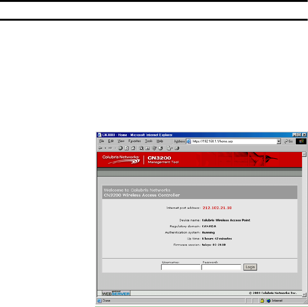
Chapter 5: The management tool 46
Starting the management tool
1. Start your Web browser.
2. Press Enter. You will be prompted to accept a Colubris Networks security
certificate. Do so to continue. (To eliminate this warning message you can
install your own certificate as described in Chapter 14.)
To safeguard the security of the CN3200, access to the management tool
must occur via a secure connection. Before this connection can be
established, you must accept a Colubris Networks security certificate. The
procedure for accepting the certificate varies depending on the browser you
are using.
3. After you accept the Colubris Networks certificate, the management tool
home page opens.
By default, the username and password are both set to admin.
Chapter 5: The management tool 47
Menu summary
The following is a brief overview of the management tool menu options. For
detailed information on each option and its parameters, consult the online
help, which is available by clicking the help icon that appears in the top right
corner of most boxes:
Home Displays basic status information on the operation of the CN3200. For a
description of the information on the home page, see page 14.
Wireless Wireless overview
Provides a summary of important wireless settings.
Wi-Fi
Use this page to configure the operating characteristics of the wireless network.
WLAN profiles
Use this page to define multiple SSIDs.
Wireless links
Use this page to define point-to-point links to other access points.
Neighborhood
Use this page to do s site survey and discover other wireless access points that
are operating nearby.
Network Address allocation
Lets you configure the CN3200 to act as a DHCP server or DHCP relay agent,
and also to setup bandwidth management.
IP routes
Lets you define routes to send traffic to the appropriate destination. This is useful
when the CN3200 is connected to a wired LAN which provides access to other
networks.
DNS
Enables you to override the default DNS servers assigned to the CN3200.
GRE
Lets you define GRE tunnels.
NAT
Lets you define static IP routes to make computers on the internal network
(WLAN or a connected wired LAN) visible to external computers. For example,
this can be used to run an FTP or Web server on the internal network.
RIP
Configures support for RIP.
Security The security menu lets you define all security-related settings.

Chapter 5: The management tool 48
RADIUS
This is where you define the settings the CN3200 uses to communicate with
external RADIUS servers.
Firewall
Configures the settings for the built-in firewall that protects the Internet port.
PPTP client
Configures the settings for the PPTP client which enables the CN3200 to
establish a secure connection to a remote PPTP server via the Internet port.
IPSec
Configures the settings for the IPSec client which enables the CN3200 to
establish a secure connection to an IPSec peer via the Internet port.
Certificates
Use this option to manage the SSL certificates used by the CN3200.
Users
This is where you define user accounts when customer authentication is handled
directly by the CN3200, rather than using a RADIUS server.
Management The management menu enables you to configure the operation of the
management tool and its SNMP implementation.
Management tool
Use this page to set the admin name and password, and define security
parameters that control access to the management tool.
SNMP
Configures SNMP properties and security settings.
System time
Configures system time.
Lets you view the status of other active Colubris access points.
Status Use this option to view the status of the various components on the CN3200.
Tools Provides diagnostic tools that can be used to investigate anomalies. Generally,
you will use these only under the direction of your reseller. These tools also
enable you to view the system log. The system log contains a record of all
significant events that occur on the CN3200. This information is useful when
troubleshooting the CN3200 with the assistance of your reseller. If needed, the
system log can be configured to forward entries to a remote syslog server on the
LAN or via the Internet.
Maintenance Lets you manage configuration and firmware files and save system information
for troubleshooting purposes.

Chapter 5: The management tool 49
Management tool security
The management tool is protected by the following security features.
Administrator
password
Access to the CN3200 management tool is protected by a username and
password to safeguard configuration settings. The factory default setting for both
is admin. It is recommended that you change both.
To change the username and/or password, do the following:
1. On the main menu, click Management. The Management tool configuration
page opens.
2. In the Administrator authentication box, enter the new username, current
password, the new password, and then repeat the new password for
confirmation.
3. Click Save when you are done.
Validating administrator logins using a RADIUS server
You can use a RADIUS server to authenticate logins to the management tool.
One advantage of this is that it enables you to create several administrator
accounts, each with its own username and password.
Important: Make sure that the RADIUS profile you select is configured and that
the administrator account is defined on a functioning RADIUS server. If not, you
will not be able to log back into the CN3200 because the administrator password
cannot be authenticated.
To setup RADIUS authentication, do the following:
1. On the main menu, click Security then click RADIUS.
2. Click Add a New Profile.
3. Define the settings for the RADIUS profile you want to use to validate
administrator logins. Either use an existing profile or add a new profile.
4. Click Save.
5. On the main menu, click Management.
6. Click Management tool.
7. In the Administrator authentication box, select the RADIUS server you
defined in step 2.
8. Click Save.
If you forget the administrator password
The only way to gain access to the management tool if you forget the
administrator password is to reset the CN3200 to factory default settings.
“Resetting to factory defaults” on page 40
Connection
security
To maintain the integrity of the configuration settings, only one user can be
connected to the management tool at a given time. To prevent the management
tool from being locked up by an idle user two mechanisms are in place:
• If a user’s connection to the management tool remains idle for more than ten
minutes, the CN3200 automatically logs the user out.

Chapter 5: The management tool 50
• If a second user connects to the management tool and logs in with the correct
username and password, the first user’s session is terminated.
HTTPS
Communications between the management station and the CN3200 occurs via
HTTPS. Before logging onto the management tool, users must accept a Colubris
Networks certificate. You can replace this certificate with your own. For more
information see, Chapter 14.
Remote management security
Secure remote management is possible using the integrated PPTP and IPSec
client software. This enables the CN3200 to create a secure tunnel to a remote
server using a public network (Internet). This can also be used to secure
automatic configuration updates and communications with a remote RADIUS
server or Web server. For details, see Chapter 10.
Security settings The CN3200 can be managed both locally and remotely for complete flexibility.
Management occurs via the Web-based management tool which resides on the
CN3200. For details see “Management scenarios” on page 44.
To configure security options
1. On the main menu, click Management. The Management tool configuration
page opens.
2. In the Security box, enable the management options you require. The
options are described in the section that follows.
3. Click Save.
Security options
Allowed addresses
Lets you define a list of IP address from which access to the management tool is
permitted. To add an entry, specify the IP address and appropriate mask and
click Add.
When the list is empty, access is permitted from any IP address.
Active interfaces
Choose the interfaces through which client stations will be able to access the
management tool.
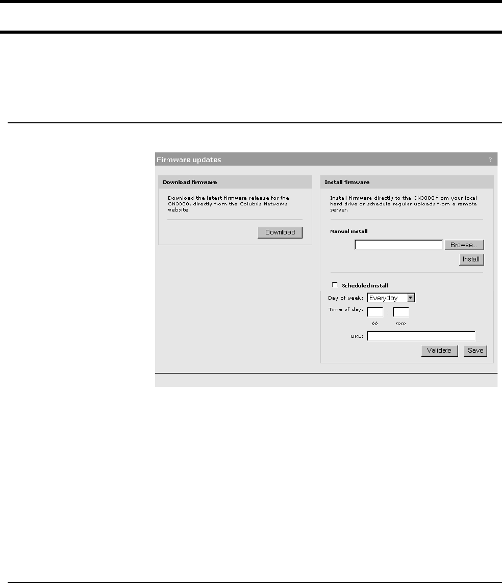
Chapter 5: The management tool 51
Firmware management
The firmware is special software that controls the operation of the CN3200.
Periodically, Colubris Networks will make new versions of the firmware available.
Firmware updates can be handled manually, automatically, or with a tool like
cURL.
Manual update 1. On the Maintenance menu, click Firmware updates.
2. In the Download firmware box, click the Download button to retrieve the
latest firmware from the Colubris Networks web site and save it to your
computer’s hard drive.
3. Unzip the file.
4. In the Install firmware box, click the Browse button and select the *.cim file
you just unzipped.
5. Click Install.
Note: The CN3200 will automatically restart after the firmware has been installed
to activate it. This will disconnect all client stations. Once the CN3200 resumes
operation, all client stations will have to reconnect.
Note: Configuration settings are preserved during firmware upgrades.
Scheduled install The CN3200 can automatically retrieve and install firmware from a local or
remote URL. By placing CN3200 firmware on a web or ftp server, you can
automate the update process for multiple units.
When the update process is triggered, the CN3200 retrieves the first few bytes of
the firmware file to determine if it is different than the active version. If different,
the firmware is download and installed. Configuration settings are preserved.
However, all connections will be terminated forcing customers to log in again.

Chapter 5: The management tool 52
Using cURL It is possible to automate management tasks using a tool like cURL. cURL is a
software client that can be used to get/send files to/from a server using a number
of different protocols (HTTP, HTTPS, FTP, GOPHER, DICT, TELNET, LDAP or
FILE).
cURL is designed to work without user interaction or any kind of interactivity. It is
available for Windows and LINUX at: http://curl.haxx.se/. You must use version
7.9.8 or higher.
The following cURL commands illustrate how to update the firmware. The
following setup is assumed:
• IP address of the CN3200’s Internet port is 24.28.15.22.
• Management access via the Internet port is enabled.
• Firmware is located in the file: CN3200.CIM
Login to the management interface.
curl --dump-header cookie.txt -s -m 60 "https://24.28.15.22/
goform/Logout?username=admin&pw=admin"
Prepare the CN3200 to receive the firmware update.
curl --cookie cookie.txt -m 60 "https://24.28.15.22/script/
firmware_init.asp"
Upload the firmware. Once the upload is complete the CN3200 will automatically
restart.
curl --cookie cookie.txt -s -m 600 -F firmware=@CN3200.cim -F
backup=Install "https://24.28.15.22/goform/ScriptUploadFirmware"
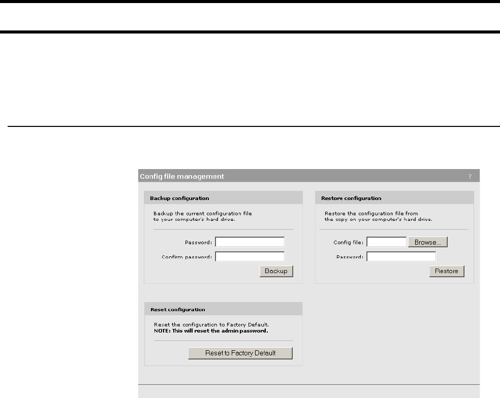
Chapter 5: The management tool 53
Configuration management
The configuration file contains all the settings that customize the operation of the
CN3200.
You can save and restore the configuration file manually, automatically, or with a
tool like cURL.
Manual
management
Use the Config file management option on the Maintenance menu to manage
your configuration file.
The following three options are available:
Backup configuration file
This option enables you to backup your configuration settings so they can be
easily restored in case of failure. This option is also used when you want to
directly edit the configuration file. See Chapter 21 for details.
Reset configuration
Use this option to return the configuration of the CN3200 to its factory default
settings.
Note: Resetting sets the administrator password to ‘admin’ and resets all
configuration settings.
Restore configuration file
Enables you to restore a configuration from a previously saved backup.
This feature enables you to maintain several configuration files with different
settings, which can be useful if you frequently need to alter the configuration of
the CN3200, or if you are managing several CN3200s from a central site.

Chapter 5: The management tool 54
Using cURL It is possible to automate management tasks using a tool like cURL. cURL is a
software client that can be used to get/send files to/from a server using a number
of different protocols (HTTP, HTTPS, FTP, GOPHER, DICT, TELNET, LDAP or
FILE).
cURL is designed to work without user interaction or any kind of interactivity. It is
available for Windows and LINUX at: http://curl.haxx.se/. You must use version
7.9.8 or higher.
The following cURL commands illustrate how to manage the configuration file.
The following setup is assumed:
• IP address of the CN3200’s Internet port is 24.28.15.22.
• Management access to the Internet port is enabled.
• Configuration file is located in CN3200.CFG.
Uploading the configuration file
1. Login to the management interface.
curl --dump-header cookie.txt -s -m 60 "https://24.28.15.22/goform/
Logout?username=admin&pw=admin"
2. Prepare the CN3200 to receive the configuration update.
curl --cookie cookie.txt -m 60 "https://24.28.15.22/script/
config_init.asp"
3. Upload the configuration file.
curl --cookie cookie.txt -s -m 600 -F config=@CN3200.cfg -F backup=Restore
"https://24.28.15.22/goform/ScriptUploadConfig"
4. Reset the CN3200 to activate the new configuration.
curl --cookie cookie.txt -s -m 60 "https://24.28.15.22/script/reset.asp"
Downloading the configuration file
1. Login to the management interface.
curl --dump-header cookie.txt -s -m 60 "https://24.28.15.22/
goform/Logout?username=admin&pw=admin"
2. Download the configuration file.
curl --cookie cookie.txt "https://24.28.15.22/download/config.cfg"
-o config.cfg
3. Logout.
curl --cookie cookie.txt -s -m 4 "https://24.28.15.22/goform/
Logout?logout=Logout"
Resetting the configuration to factory defaults
1. Login to the management interface.
curl --dump-header cookie.txt -s -m 60 "https://24.28.15.22/
goform/Logout?username=admin&pw=admin"
2. Reset configuration to factory defaults.
Chapter 5: The management tool 55
curl --cookie cookie.txt -m 5 "https://24.28.15.22/goform/
ScriptResetFactory?reset=Reset+to+Factory+Default"
3. Reset the CN3200 to activate the new configuration.
curl --cookie cookie.txt -s -m 60 "https://24.28.15.22/script/
reset.asp"
Chapter 5: The management tool 56

Chapter 6: WLAN configuration 57
Chapter 6: WLAN configuration:
Chapter 6
WLAN configuration
This chapter explains how to setup a wireless network with the CN3200.
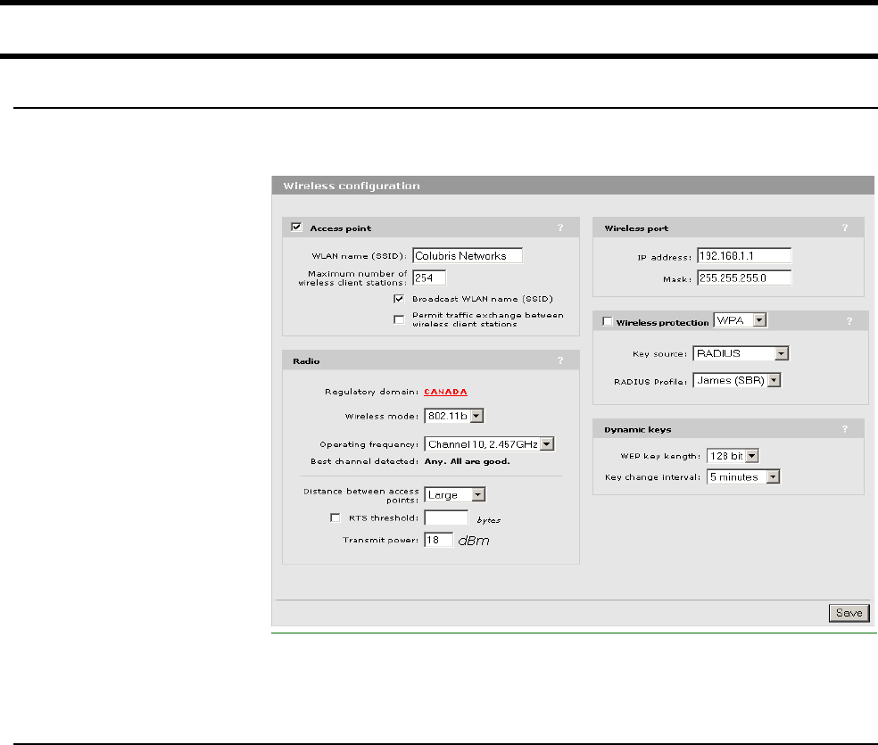
Chapter 6: WLAN configuration 58
Setting up the wireless LAN
Configuration
procedure
1. On the main menu, click Wireless, and then click Wi-Fi. The Wireless
configuration page opens.
2. Configure the parameters as described in the sections that follow.
3. Click Save when you are done.
Access point Enable this option to activate the wireless access point. When this option is
disabled, wireless client stations will not be able to connect.
WLAN name (SSID)
Specify a name to uniquely identify your wireless network. Each client computer
that wants to connect to the CN3200 must use this name. The name is case-
sensitive.
Maximum number of wireless client stations
Specify the maximum number of wireless client stations that can be connected to
the CN3200 at the same time.
Important: The total number of wireless connections that can be active at any
given time across all WLAN profiles is 100.
Broadcast WLAN name (SSID)
When this option is enabled, the CN3200 will broadcast its wireless network
name (SSID) to all client stations. Most wireless adapter cards have a setting that
enables them to automatically discover access points that broadcast their names
and automatically connect to the one with the strongest signal.
If you disable this option, client stations will have to specify the network name you
enter for WLAN name when they connect.

Chapter 6: WLAN configuration 59
Radio Regulatory domain
This parameter is not supported for all wireless cards. It will only appear when
the appropriate wireless card is installed in the CN3200.
Choose your country. This changes the available operating frequencies
according to the regulatory standards in your country.
Wireless mode
Choose the mode the radio will operate in.
Operating frequency
Select the frequency the CN3200 will operate at. The frequencies that are
available are determined by the radio installed in your CN3200 and the
regulations that apply in your country.
For optimum performance, choose a frequency that differs from other wireless
access points operating in neighboring cells by at least 25 MHz. For more
information see “Configuring overlapping wireless cells” on page 66. Consult the
Wireless > Neighborhood page to view a list of access points currently
operating in your area. (If this option is not visible, it is not supported by the radio
installed in the CN3200.)
Best channel detected
The CN3200 automatically scans all available channels and lists the channel with
the best signal quality. Use this as a guide to select the best operating frequency.
Distance between access points
Use this parameter to adjust the receiver sensitivity of the CN3200. This
parameter should only be changed if:
• you have more than one wireless access point installed in your location
• you are experiencing throughput problems
In all other cases, use the default setting of Large.
If you have installed multiple CN3200s, reducing the receiver sensitivity of the
CN3200 from its maximum will help to reduce the amount of crosstalk between
the wireless stations to better support roaming clients. By reducing the receiver
sensitivity, client stations will be more likely to connect with the nearest access
point.
RTS threshold
Use this parameter to control collisions on the link that can reduce throughput. If
the Status -> Wireless page shows increasing values for Tx multiple retry
frames or Tx single retry frames, you should adjust this value until the errors
clear up. Start with the largest value and slowly decrease until errors are
minimized. Note that using a small value for RTS threshold can affect
throughput.
How it works
If a packet is larger than the threshold, the local CN3200 will hold it and issue a
request to send (RTS) message to the remote CN3200. Only when the remote
CN3200 replies with a clear to send (CTS) message will the local CN3200 send
the packet. Packets smaller than the threshold are transmitted without this
handshake.
Transmit power
This parameter is not supported for all wireless cards. It will only appear when
the appropriate wireless card is installed in the CN3200.
Use this parameter to set the transmission power of the wireless radio.
Depending on the card you may have the option of selecting values from a list or
by directly specifying power in dBM.

Chapter 6: WLAN configuration 60
Important: Regardless of the power value you set, the maximum power output
will be adjusted internally based on the selected regulatory domain (if supported)
and operating frequency.
List values
• HIGH: Sets the maximum transmission power the wireless card is capable of. It
will be either 100mW (20dBm) or 200mW for North America (23dBm).
• MEDIUM - 17dBm (17 dBm)
• LOW - 13dBm (13 (dBm)
Wireless port IP address
Specify the IP address you want to assign to the wireless port. By default, this is
192.168.1.1.
Note: Changing the IP address of the wireless port will cause you to lose contact
with the management tool. To reconnect, restart your computer or release/renew
your IP address, and enter the new address into your browser.
Note: If wireless client stations are currently using the CN3200, changing the IP
address will cause them to lose their connections. To reconnect, each client must
reboot or release/renew its IP address.
Mask
Specify the appropriate subnet mask for the IP address you specified.
Wireless
protection
Select the type of protection you want to use for the wireless network.
WPA
This option enables support for users with WPA client software.
Key transmission protection
This option determines how the TKIP keys are generated.
• RADIUS: The CN3200 obtains the MPPE key from the RADIUS server. This is
a dynamic key that changes each time the user logins in and is authenticated.
The MPPE key is used to generate the TKIP keys that encrypt the wireless
data stream.
• Preshared Key: The CN3200 uses the key you specify to generate the TKIP
keys that encrypt the wireless data stream. Since this is a static key, it is not as
secure as the RADIUS option.
Key/Confirm key
Specify a key that is between 8 and 64 characters in length.
802.1x
This option enables support for users with 802.1x client software. The CN3200
supports 802.1x client software that uses EAP-TLS, EAP-TTLS, and PEAP.
RADIUS profile
Select the RADIUS profile the CN3200 will use to validate user logins.

Chapter 6: WLAN configuration 61
Dynamic WEP encryption
Enable the use of dynamic WEP keys for all 802.1x sessions. Dynamic key
rotation occurs on key 1, which is the broadcast key. Key 0 is the pairwise key. It
is automatically generated by the CN3200.
WEP
Key 1, 2, 3, 4
The number of characters you specify for a key determines the level of encryption
the CN3200 will provide.
• For 40-bit encryption, specify 5 ASCII characters or 10 HEX digits.
• For 128-bit encryption, specify 13 ASCII characters or 26 HEX digits.
When encryption is enabled, wireless stations that do not support encryption
cannot communicate with the CN3200. The definition for each encryption key
must be the same on the CN3200 and all client stations. Keys must also be in the
same position. For example, if you are using key 3 to encrypt transmissions, then
each client station must also define key 3 to communicate with the CN3200.
Transmission key
Select the key the CN3200 will use to encrypt transmitted data. All four keys are
used to decrypt received data.
Key format
Select the format you used to specify the encryption keys:
ASCII
ASCII keys are much weaker than carefully chosen HEX keys. You can include
ASCII characters between 32 and 126, inclusive, in the key. However, note that
not all client stations support non-alphanumeric characters such as spaces,
punctuation, or special symbols in the key.
HEX
Your keys should only include the following digits: 0-9, a-f, A-F
Dynamic keys WEP key length
This setting determines the level of encryption the CN3200 will provide for 802.1x
and WPA.
Key change interval
Specifies how often key rotation occurs for 802.1x and WPA.
Addresses
If the LAN and wireless ports are not bridged (Network > Ports > LAN port
page), the CN3200 provides a separate DHCP server on each port. Use the
check box to enable/disable each one.
The CN3200 provides its own IP address as the DNS server address. The
CN3200 acts as a DNS relay and redirects all DNS requests to the DNS servers
specified on the DNS/WINS page.
If a WINS server is defined on the DNS/WINS page, its address is provided to
DHCP clients as well.

Chapter 6: WLAN configuration 62
Start / End
Specify the starting and ending IP addresses that define the range of addresses
the DHCP server can assign to client stations.
Gateway
Specify the IP address of the default gateway the CN3200 will return to DHCP
clients.
Address/mask
Shows the current settings for the port.
The host name in the currently installed SSL certificate is automatically assigned
as the domain name of the CN3200. The factory default SSL certificate that is
installed on the CN3200 has the host name wireless.colubris.com.
You do not have to add this name to your DNS server for it to be resolved. The
CNx intercepts all DNS requests it receives on the wireless or LAN ports. It
resolves any request that matches the certificate host name by returning the IP
address assigned to the Internet port. All other DNS requests are forwarded to
the appropriate DNS servers as configured on the Network > DNS/WINS page.
To summarize, this means that by default, any DNS request by a client station on
the wireless or LAN ports that matches wireless.colubris.com will return the IP
address of the CN3200’s Internet port.
4.
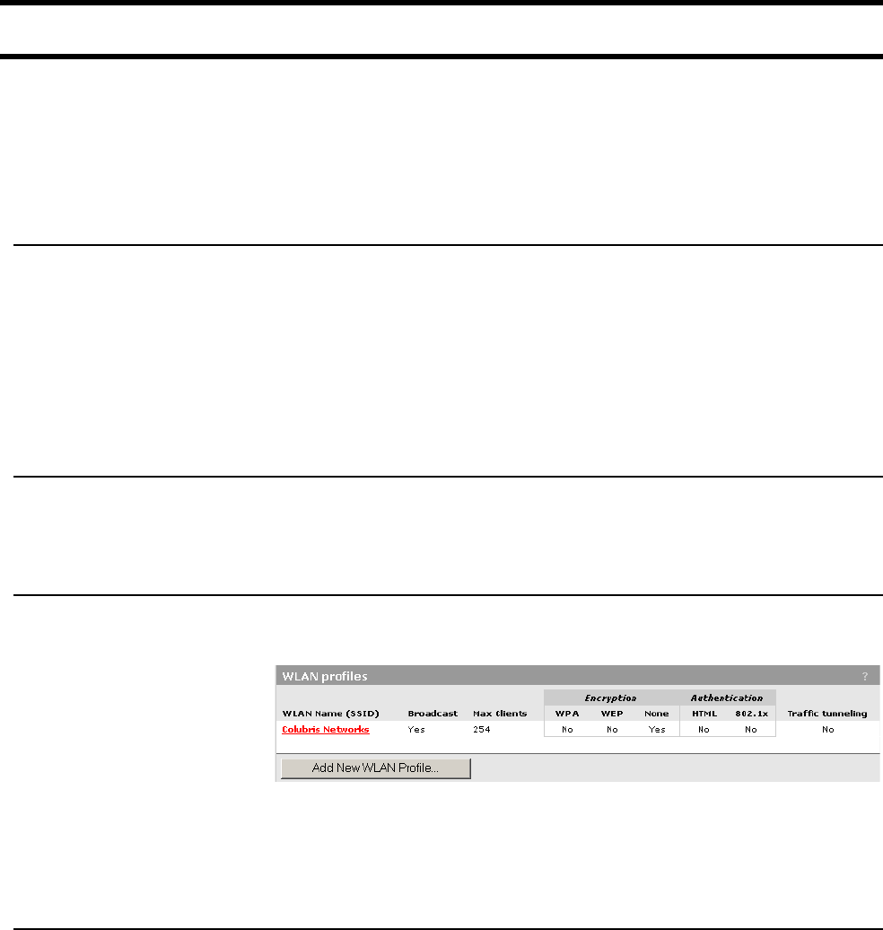
Chapter 6: WLAN configuration 63
Wireless profiles
The CN3200 enables you to create multiple wireless networks (also knows as
virtual access points) all sharing the same wireless port. Each network has its
own SSID (network name), BSSID (MAC address), and configuration settings
that are defined in a profile. Up to 16 profiles can be created.
All profiles shared basic settings defined in the Default profile (see below).
Default profile The default profile (named “Colubris Networks”) controls the settings for the
parameters that are shared by all profiles. This includes:
• radio settings (operating frequency, distance between access points, transmit
power)
• wireless port address and mask
• dynamic key length and key change interval for 802.1x/WPA
Configure this profile on the Wireless > Wi-Fi page.
Configuration
considerations
Up to 16 profiles can be defined. Since all profiles share the same radio,
bandwidth is also shared. To manage the load on the network, each profile can
should be configured to limit the maximum number of wireless client stations.
To create a
wireless profile
1. On the main menu, click Wireless, and then click WLAN profiles. The WLAN
profiles page opens. Initially, it displays the default WLAN profile.
2. Click Add New Profile.
3. Specify the settings for the profile. Refer to the sections that follow for details.
4. Click Save when you are done.
Access point Enable this option to activate the wireless access point. When this option is
disabled, wireless client stations will not be able to connect.
WLAN name (SSID)
Specify a name to uniquely identify your wireless network. Each client computer
that wants to connect to this profile must use this name. The name is case-
sensitive.
Maximum number of wireless client stations
Specify the maximum number of wireless client stations that can be associated
with this SSID at the same time.
Important: The total number of wireless connections that can be active at any
given time across all WLAN profiles is 100.

Chapter 6: WLAN configuration 64
Broadcast WLAN name (SSID)
When this option is enabled, the CN3200 will broadcast its wireless network
name (SSID) of this profile to all client stations. Most wireless adapter cards have
a setting that enables them to automatically discover access points that
broadcast their names and automatically connect to the one with the strongest
signal.
If you disable this option, client stations will have to specify the network name you
enter for WLAN name when they connect.
RADIUS
accounting
Enable this option to have the CN3200 generate a RADIUS accounting request
ON/OFF for each user authentication. The CN3200 respects the RADIUS
interim-update-interval attribute if present inside the RADIUS access accept of
the authentication.
Wireless
protection
Select the type of protection you want to use for the wireless network.
WPA
This option enables support for users with WPA client software.
Key transmission protection
This option determines how the TKIP keys are generated.
• RADIUS: The CN3200 obtains the MPPE key from the RADIUS server. This is
a dynamic key that changes each time the user logins in and is authenticated.
The MPPE key is used to generate the TKIP keys that encrypt the wireless
data stream.
• Preshared Key: The CN3200 uses the key you specify to generate the TKIP
keys that encrypt the wireless data stream. Since this is a static key, it is not as
secure as the RADIUS option.
Key/Confirm key
Specify a key that is between 8 and 64 characters in length.
802.1x
This option enables support for users with 802.1x client software. The CN3200
supports 802.1x client software that uses EAP-TLS, EAP-TTLS, and PEAP.
RADIUS profile
Select the RADIUS profile the CN3200 will use to validate user logins.
Dynamic WEP encryption
Enable the use of dynamic WEP keys for all 802.1x sessions. Dynamic key
rotation occurs on key 1, which is the broadcast key. Key 0 is the pairwise key. It
is automatically generated by the CN3200.
WEP
Key 1, 2, 3, 4
The number of characters you specify for a key determines the level of encryption
the CN3200 will provide.

Chapter 6: WLAN configuration 65
• For 40-bit encryption, specify 5 ASCII characters or 10 HEX digits.
• For 128-bit encryption, specify 13 ASCII characters or 26 HEX digits.
When encryption is enabled, wireless stations that do not support encryption
cannot communicate with the CN3200. The definition for each encryption key
must be the same on the CN3200 and all client stations. Keys must also be in the
same position. For example, if you are using key 3 to encrypt transmissions, then
each client station must also define key 3 to communicate with the CN3200.
Transmission key
Select the key the CN3200 will use to encrypt transmitted data. All four keys are
used to decrypt received data.
Key format
Select the format you used to specify the encryption keys:
ASCII
ASCII keys are much weaker than carefully chosen HEX keys. You can include
ASCII characters between 32 and 126, inclusive, in the key. However, note that
not all client stations support non-alphanumeric characters such as spaces,
punctuation, or special symbols in the key.
HEX
Your keys should only include the following digits: 0-9, a-f, A-F
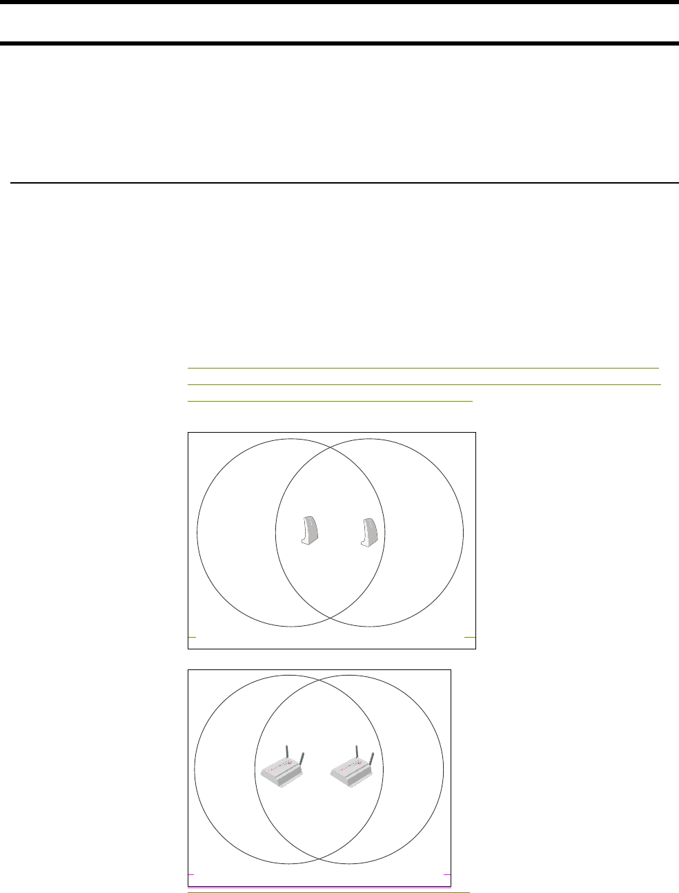
Chapter 6: WLAN configuration 66
Configuring overlapping wireless cells
Overlapping wireless cells are caused when two or more access points are within
transmission range of each other. This may be under your control (when setting
up multiple cells to cover a large location), or out of your control (when your
neighbors set up their own wireless networks). In either case, the problems you
face are similar.
Performance
degradation and
channel
separation
When two wireless cells operating on the same frequency overlap, it can cause a
reduction in throughput in both cells. This occurs because a wireless station that
is attempting to transmit will defer (delay) its transmission if another station is
currently transmitting. On a network with many clients and a lot of traffic, this can
severely affect performance as stations defer multiple times before the channel
becomes available. If a station is forced to delay its transmission too many times,
data may be lost.
Delays and lost transmissions can severely reduce throughput on a network. Use
the Wireless option on the Status menu to view this information on your
network.
The following example shows two overlapping wireless cells operating on the
same frequency. Since both access points are within range of each other, the
number of deferred transmissions will be large.
Overlapping wireless cells can cause transmission delays.
The solution to this problem is to set the two networks to different channels with
as great a separation as possible in their operating frequencies. This reduces
cell 1 cell 2
cell 1 cell 2
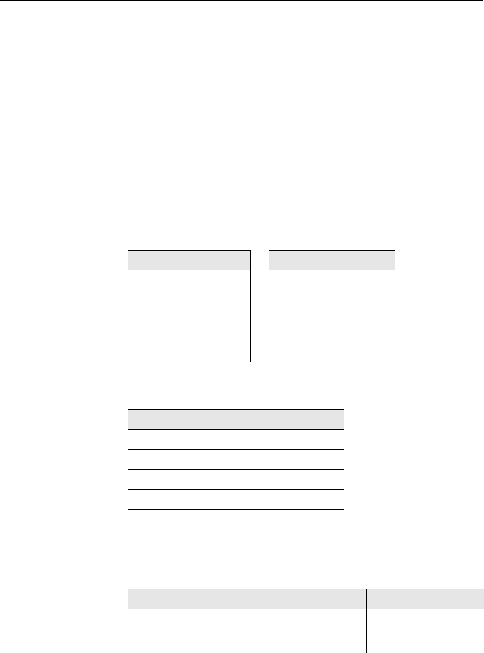
Chapter 6: WLAN configuration 67
cross-talk, and enables client stations connected to each access point to transmit
at the same time.
Choosing
channels
The minimum recommended separation between channels is 25 Mhz. Note
however, that this is the recommended minimum. Two channels with this
separation will always perform worse than two channels using the maximum
separation. So, it is always best to use the greatest separation possible between
overlapping networks.
With the proliferation of wireless networks, it is very possible that the wireless
cells of access points outside your control may overlap your intended area of
coverage. To help you choose the best operating frequency, the CN3200 will
automatically scan all channels and provide a recommendation on the Wireless
> Wi-Fi page. To generate a list of all access points operating near you and view
their operating frequencies, go to Wireless > Neighborhood.
The set of available channels is automatically determined by the CN3200 based
on the Country setting you define on the Wi-Fi page, which means that the
number of non-overlapping channels available to you will also vary. This will
affect how you setup your multi-cell network.
Example
When operating in 802.11b/g mode, the CN3200 supports the following 14
channels in the 2.4 Ghz band:
However, the number of channels available for use in a particular country are
determined by the regulations defined by the local governing body. For example:
Since the minimum recommended separation between overlapping channels is
25 MHz (5 cells), the recommended maximum number of overlapping cells you
can have in most regions is three. For example:
Channel Frequency Channel Frequency
1
2
3
4
5
6
7
2412
2417
2422
2427
2432
2437
2442
8
9
10
11
12
13
14
2447
2452
2457
2462
2467
2472
2477
Region Available channels
North America 1 to 11
Japan 1 to 14
Europe 1 to 13
France 1 to 13
Spain 10 to 13
North America Europe Japan
• cell 1 on channel 1
• cell 2 on channel 6
• cell 3 on channel 11
• cell 1 on channel 1
• cell 2 on channel 7
• cell 3 on channel 13
• cell 1 on channel 1
• cell 2 on channel 7
• cell 3 on channel 14
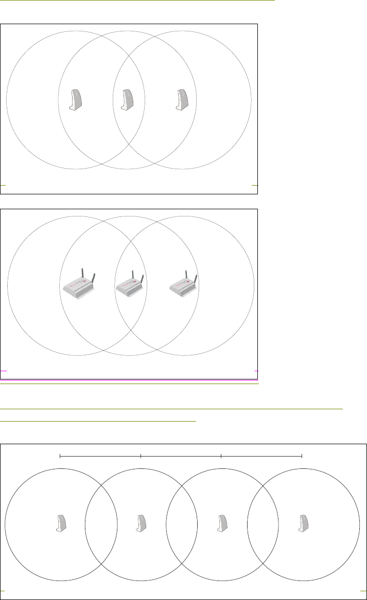
Chapter 6: WLAN configuration 68
In North America, you would create the following installation:
Reducing transmission delays by using different operating frequencies.
However, It is possible to stagger your cells to reduce overlap and increase
channel separation. Consider the following:
cell 1
channel = 1
cell 3
channel = 11
cell 2
channel = 6
cell 1
channel = 1
cell 3
channel = 11
cell 2
channel = 6
cell 1
channel = 1
cell 2
channel = 6
cell 3
channel = 11
cell 4
channel 1
100m 100m 100m
300 feet 300 feet 300 feet
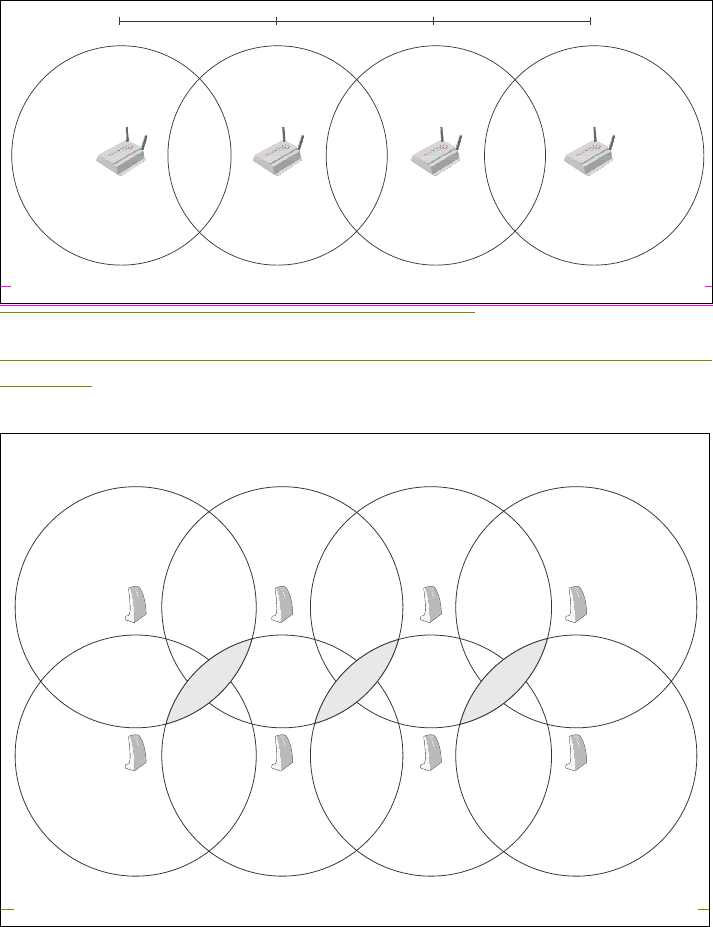
Chapter 6: WLAN configuration 69
Using only three frequencies across multiple cells (North America).
This strategy can be expanded to cover an even larger area using three channels
as follows:
cell 1
channel = 1
cell 2
channel = 6
cell 3
channel = 11
cell 4
channel 1
150m 150m 150m
450 feet 450 feet 450 feet
cell 1
channel = 1
cell 5
channel = 11
cell 2
channel = 6
cell 6
channel = 1
cell 3
channel = 11
cell 7
channel = 6
cell 4
channel 1
cell 8
channel 11
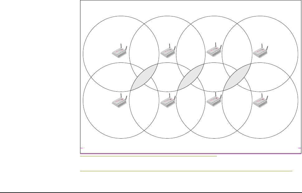
Chapter 6: WLAN configuration 70
Using three frequencies to cover a large area (North America).
The areas in gray indicate where two cells using the same frequency overlap.
Distance between
access points
In environments where the number of wireless frequencies are limited, it can be
beneficial to adjust the receiver sensitivity of the CN3200. To make the
adjustment, open the Wi-Fi page on the Wireless menu.
For most installations, the large setting should be used. However, if you are
installing multiple CN3200s, and the channels available to you do not provide
enough separation, then reducing the receiver sensitivity can help you reduce the
amount of crosstalk between the CN3200s.
Another benefit to using reduced settings is that it will improve roaming
performance. Client stations will switch between CN3200s more frequently.
Note: The distance between access points option provides the best performance
benefit when client stations are equipped with wireless adapters that are
configured with the same setting. However, not all manufacturers support this
setting.
cell 1
channel = 1
cell 5
channel = 11
cell 2
channel = 6
cell 6
channel = 1
cell 3
channel = 11
cell 7
channel = 6
cell 4
channel 1
cell 8
channel 11
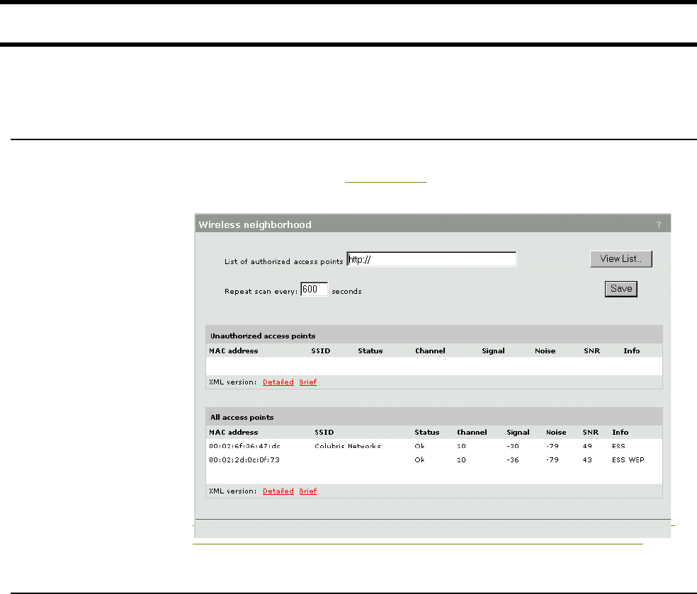
Chapter 6: WLAN configuration 71
Conducting a site survey and finding rouge access points
The integrated site survey tool permits easy detection of currently operating
access points, and lets you automatically flag unauthorized (rouge) units.
Conducting a site
survey
To discover the operating frequencies of other access points in your area, open
the Wireless > Neighborhood page. The CN3200 will automatically scan to find
all active access points. For example:
Note: If an access point is not broadcasting its name, the SSID is blank.
Identifying
unauthorized
access points
Improperly configured wireless access points can seriously compromise the
security of a corporate network. Therefore, it is important that they be identified
as quickly as possible.
The wireless neighborhood feature can be configured to automatically list all non-
authorized access points that are operating nearby.
To identify unauthorized access points, the CN1050 compares the MAC address
of each discovered access point against the list of authorized access points
(which you must define). If the discovered access point does not appear in the
list, it is displayed in the Unauthorized access points list.
List of authorized access points
The format of this file is XML. Each entry in the file is composed of two items:
MAC address and SSID. Each entry should appear on a new line. The easiest
way to create this file is to wait for a scan to complete, then open the list of all
access points in Brief format. Edit this list so that it contains only authorized
access points and save it. Then, specify the address of this file for the List of
authorized access points parameter.
Chapter 6: WLAN configuration 72

Chapter 7: Connecting to a wired LAN 73
DRAFT
Chapter 7: Connecting to a wired LAN
Chapter 7
Connecting to a wired LAN
This chapter explains how to configure a connection to a wired LAN.
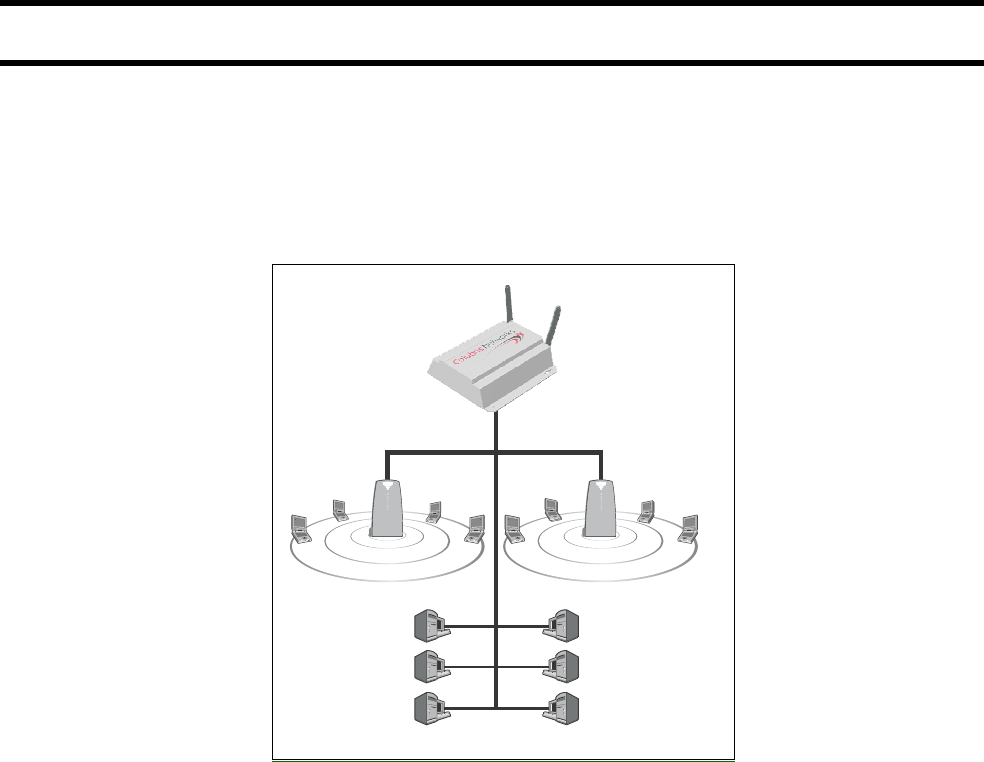
Chapter 7: Connecting to a wired LAN 74
DRAFT
Overview
The CN3200 provides a LAN port for connection to a wired network. Generally,
this is used to:
• connect the CN3200 to one or more CN300s
• connect wired computers to the public access network
For example:
P
U
B
L
I
C
W
L
A
N
P
U
B
L
I
C
W
L
A
N
CN3200
CN300CN300

Chapter 7: Connecting to a wired LAN 75
DRAFT
Addressing issues
Using DHCP To configure the DHCP server
1. Click Network.
2. Click Address Allocation.
3. Select the DHCP server and click Configure.
4. Configure the appropriate settings. Refer to the online help for details.
5. Click Save.
LAN port address
The CN3200 connects to the wired LAN via its LAN port. You must assign a static
IP address to this port because the CN3200 cannot function as a DHCP client on
its LAN port.
To assign a static LAN port address
1. Click Wireless.
2. Click Wi-Fi.
3. Assign the new IP address and associated mask in the Wireless port box.
4. Click Save.
DHCP relay agent
If you have multiple CN3200s on your network, configuring each one to act as a
DHCP relay agent enables you to assign all IP addresses from a single DHCP
server to reduce management overhead.
Take note of the following regarding the DHCP relay option on the CN3200:
• DHCP relay occurs via the CN3200’s Internet port.
• DHCP relay is not supported if PPPoE is active on the Internet port.
• DHCP relay is will not function if the firewall is set to High and NAT is enabled
on the Internet port. The reason for this it that the DCHP server must be able to
ping the assigned address to prevent duplicate assignments.
• Routes must be defined on the remote DHCP server so that it can successfully
send DHCP packets back to the DHCP relay agent running on the CN3200.
These routes must identify the segment assigned to the CN3200’s LAN port.
To activate the DHCP relay agent
1. Click Network.
2. Click Address allocation.
3. Select the DHCP relay agent and click Configure.
4. Specify the address for the primary and secondary DHCP servers.
5. Click Save.
Using static
addressing
If the wired LAN uses static IP addressing, you have two options:
1. Disable the DHCP server on the CN3200 and manually define static IP
addresses for all client stations.
Chapter 7: Connecting to a wired LAN 76
DRAFT
2. Leave the DCHP server on the CN3200 operational and configure it to assign
IP addresses outside the range of the static addresses already in use on the
wired LAN.

Chapter 8: Connecting to the Internet 77
DRAFT
Chapter 8: Connecting to the Internet
Chapter 8
Connecting to the Internet
This chapter explains how to connect the CN3200 to the Internet via a
broadband modem and how to use the security features provided by the
firewall and network address translation

Chapter 8: Connecting to the Internet 78
DRAFT
Connecting cables
Connect cables as follows:
1. Turn off your broadband modem, then turn it back on.
2. Use a standard Ethernet cable to connect the CN3200 Internet port to the
broadband modem.
3. If the CN3200 is already running, press the reset button to restart it.

Chapter 8: Connecting to the Internet 79
DRAFT
Configuring the Internet connection
This section describes how to configure the CN3200 to successfully connect to
the Internet. To create a secure connection to a remote network via the Internet,
see Chapter 10.
The Internet port can also be used to link the CN3200 to a local area network.
Just choose the addressing method that is appropriate for your setup.
Configuration
procedure
1. On the main menu, click Network.
2. Click Ports.
3. In the table, click Internet port. The Internet port configuration page opens.
4. The CN3200 automatically attempts to detect the type of server on the
network. If incorrect, select the correct option and configure the settings
described in the sections that follow.
5. Click Save when you are done.
Assign IP address via
PPPoE client
Point-to-point protocol over Ethernet. Your ISP will automatically assign an IP
address to the CN3200. You need to supply a username and password so the
CN3200 can log on.
DHCP client
Dynamic host configuration protocol. Your ISP’s DHCP server will automatically
assign an address to the CN3200, which functions as a DHCP client.
Static
This option enables you to manually assign an IP address to the CN3200 Internet
port.
Link
The title bar shows the current status of the link.
Speed
• Auto: Lets the CN3200 automatically set port speed based on the type of
equipment it is connected to.
• 10: Forces the port to operate at 10 mbps.
Duplex
• Auto: Lets the CN3200 automatically set duplex mode based on the type of
equipment it is connected to
• Full: Forces the port to operate in full duplex mode.
• Half: Forces the port to operate in half duplex mode.
Network address translation (NAT)
Enable this option to permit all the computers on the wireless network to
simultaneously share the connection to the Internet using a single ISP account. If
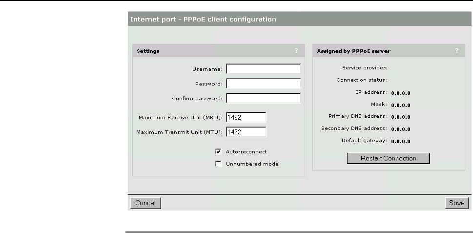
Chapter 8: Connecting to the Internet 80
DRAFT
you disable NAT, client stations will not be able to access the Internet unless their
IP addresses are valid on the Internet.
If the CN3200 is connected to a wired LAN, computers on the wired LAN can
also take advantage of NAT to share the Internet connection.
PPPoE client
Settings
Username
Specify the username assigned to you by your ISP. The CN3200 will use this
username to log on to your ISP when establishing a PPPoE connection.
Password/Confirm password
Specify the password assigned to you by your ISP. The CN3200 will use this
password to log on to your ISP when establishing a PPPoE connection.
Maximum Receive Unit (MRU)
Maximum size (in bytes) of a PPPoE packet when receiving. Changes to this
parameter only should be made according to the recommendations of your ISP.
Incorrectly setting this parameter can reduce the throughput of your Internet
connection.
Maximum Transmit Unit (MTU)
Maximum size (in bytes) of a PPPoE packet when transmitting. Changes to this
parameter should only be made according to the recommendations of your ISP.
Incorrectly setting this parameter can reduce the throughput of your Internet
connection.
Auto-reconnect
The CN3200 will automatically attempt to reconnect if the connection is lost.
Un-numbered mode
This feature is useful when the CN3200 is connected to the Internet and NAT is
not being used. Instead of assigning two IP addresses to the CN3200, one to the
Internet port and one to the LAN port, both ports can share a single IP address.
This is especially useful when a limited number of IP addresses are available to
you.
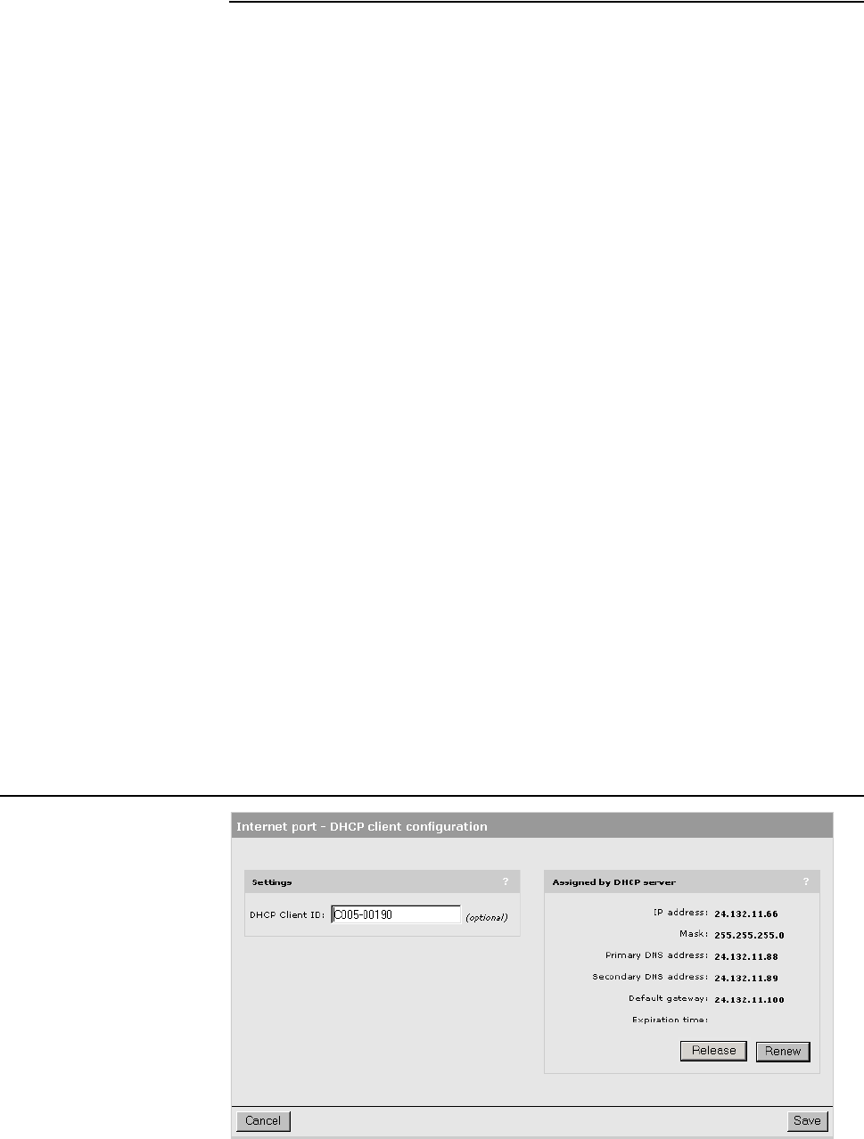
Chapter 8: Connecting to the Internet 81
DRAFT
Assigned by PPPoE server
These settings are assigned to the CN3200 by your ISP’s PPPoE server. The
Internet connection is not active until this occurs.
Service provider
Identifies your Internet service provider. Not all ISPs provide this information.
Connection status
Indicates the state of the PPPoE connection. If the connection is not active, a
message indicates why.
IP address
Identifies the IP address assigned to the CN3200 by the ISP.
Mask
Identifies the subnet mask that corresponds to the assigned IP address.
Primary DNS address
Identifies the IP address of the main DNS server the CN3200 will use to resolve
DNS requests.
Secondary DNS address
Identifies the IP address of the backup server the CN3200 will use to resolve
DNS requests.
Default gateway
Identifies the IP address of the gateway the CN3200 will forward all outbound
traffic to.
Restart Connection button
Click this button to manually establish the PPPoE connection. During normal
operation, you will not need to do this because the CN3200 will automatically
reconnect if the PPPoE connection is interrupted. However, for certain types of
connection failures, the CN3200 may not be able to re-establish the connection,
even after several retries. When this occurs, the cause of the failure is displayed
in the Connection status field and you must click the Restart Connection
button to manually establish the connection.
DHCP client

Chapter 8: Connecting to the Internet 82
DRAFT
Settings
DHCP client ID
Specify an ID to identify the CN3200 to the DHCP server. This parameter is not
required by all ISPs.
Assigned by DHCP server
These settings are assigned to the CN3200 by your ISP’s DHCP server. The
Internet connection is not active until this occurs.
IP address
Identifies the IP address assigned to the CN3200 by the ISP.
Mask
Identifies the subnet mask that corresponds to the assigned IP address.
Primary DNS address
Identifies the IP address of the main DNS server the CN3200 will use to resolve
DNS requests.
Secondary DNS address
Identifies the IP address of the backup server the CN3200 will use to resolve
DNS requests.
Default gateway
Identifies the IP address of the gateway the CN3200 will forward all outbound
traffic to.
Expiration time
Indicates how long the address is valid.
Release
Click to release the CN3200’s IP address.
Renew
Click to renew the CN3200’s IP address.
Static addressing Settings
IP address
Specify the static IP address you want to assign to the port.
Address mask
Select the appropriate mask for the IP address you specified.
Default gateway
Identifies the IP address of the gateway the CN3200 will forward all outbound
traffic to.
Note:
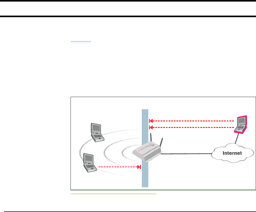
Chapter 8: Connecting to the Internet 83
DRAFT
Firewall
To safeguard your network from intruders, the CN3200 features a customizable
firewall. The firewall stops external computers from gaining access to the
wireless network through the Internet port.
The firewall operates on the traffic streaming through the Internet port. It can be
used to control both incoming and outgoing data.
The CN3200 offers a number of predefined rules to let you achieve the required
security level without going to the trouble of designing your own rules.
If the CN3200 is connected to a wired LAN, the firewall protects the wired LAN as
well.
Blocking unauthorized access with the firewall.
Firewall presets The easiest way to make use of the firewall is to use one of the preset settings.
Three levels of security are provided:
•High: Permits all outgoing traffic. Blocks all externally initiated connections.
•Medium: Same as High except that it permits incoming PPTP and IPSec
connections.
•Low: Permits all incoming and outgoing traffic, except for NetBIOS traffic. Use
this option if you require active FTP sessions.
Important: If you enable access to the Management tool or SNMP interface via
the Internet port (you do this on the Management tool or SNMP pages), the
appropriate rules are automatically added to the firewall to allow this traffic. If you
modify or delete these rules, it will affect remote access.
The following tables indicate how some common applications are affected by the
preset firewall settings.
syn attack
telnet
Integrated
Firewall
ftp
Hacker

Chapter 8: Connecting to the Internet 84
DRAFT
Outgoing traffic
Incoming traffic
1Most Web browsers execute FTP in active mode. Some browsers provide a
configuration setting that enables you to alter this. For example, in Internet
Explorer choose Internet options on the Tools menu, click the Advanced tab,
and then under Browsing enable Use Passive FTP for compatibility with
some firewalls and DSL modems.
Firewall setting
Application Low Medium High
FTP (passive mode)1Passed Passed Passed
FTP (active mode)1Passed Passed Passed
Web (HTTP, HTTPS) Passed Passed Passed
SNMP Passed Passed Passed
Telnet Passed Passed Passed
Windows networking Blocked Blocked Blocked
ping Passed Passed Passed
PPTP from client
station to remote server
Passed Passed Passed
NetMeeting (make call) Passed Passed Passed
IPSec pass-through Passed Passed Blocked
NetBIOS Blocked Blocked Blocked
Firewall setting
Application Low Medium High
FTP (passive mode)1Passed Blocked Blocked
FTP (active mode)1Passed Blocked Blocked
Web (HTTPS) Passed Blocked Blocked
Web (HTTP) Passed Blocked Blocked
Telnet Passed Blocked Blocked
Windows networking Blocked Blocked Blocked
PPTP from remote
client to a server on
the local network
Passed Passed Blocked
ping client on local
network
Passed Blocked Blocked
IPSec pass-through Passed Passed Blocked
NetBIOS Blocked Blocked Blocked
NetMeeting (receive
call)
Passed Blocked Blocked
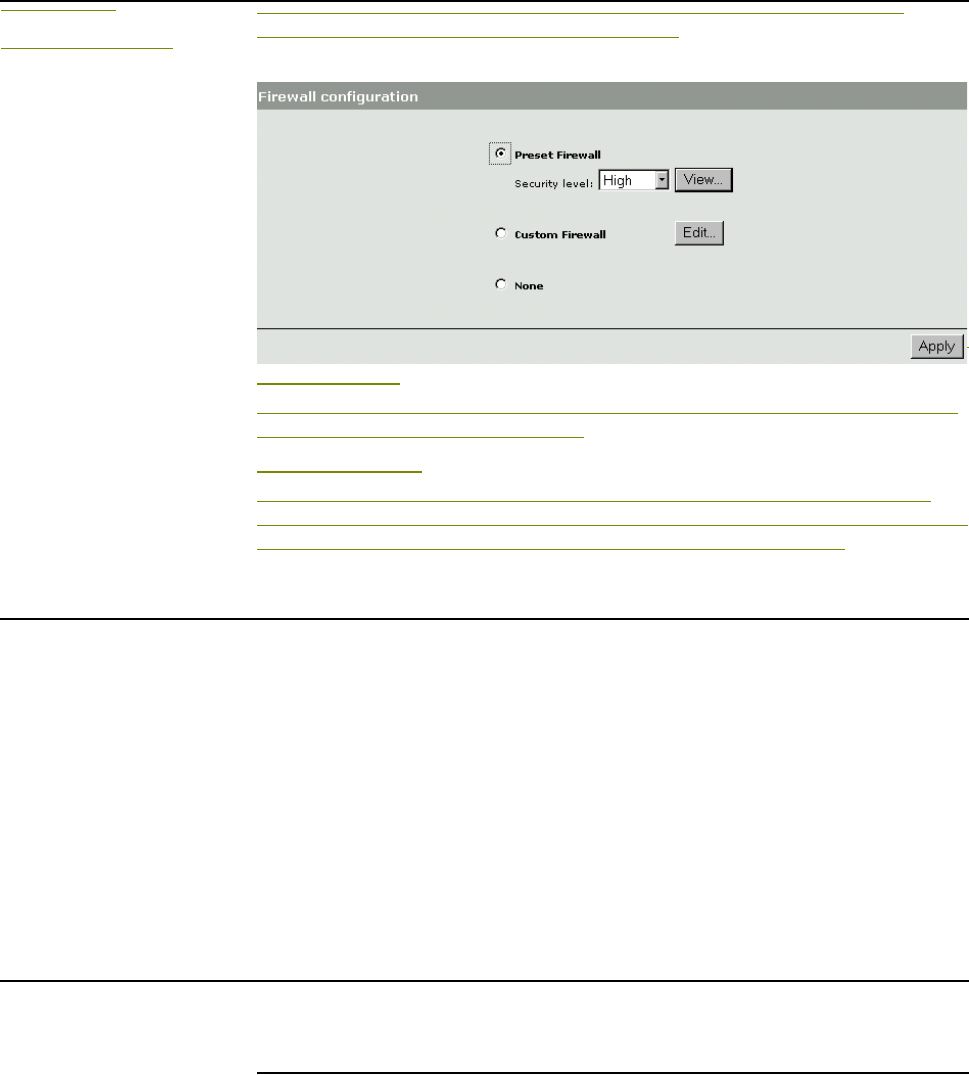
Chapter 8: Connecting to the Internet 85
DRAFT
Firewall
configuration
To configure the firewall, on the main menu, click Security and then click
Firewall. The firewall configuration page opens.
Preset firewall
The easiest way to make use of the firewall is to use one of the preset settings.
Three levels of security are provided:
Custom Firewall
If you have specific security requirements, you may want to create a custom
firewall. This enables you to target specific protocols or ports. See the examples
that follow for applications that require the use of a custom firewall.
Customizing the
firewall
To customize the firewall, you define one or more rules. A rule lets you target a
specific type of data. If the CN3200 finds data that matches the rule, the rule is
triggered, and the data is rejected by the firewall.
Rules operate on IP datagrams (sometimes also called packets). Datagrams are
the individual packages of data that travel on an IP network. Each datagram
contains addressing and control information along with the data it is transporting.
The firewall analyses the addressing and control information to apply the rules
you define.
The CN3200 applies the firewall rules in the order that they appear in the list. An
intelligent mechanism automatically adds the new rules to the list based on their
scope. Rules that target a large amount of data are added at the bottom. Rules
that target specific addresses appear at the top.
Firewall examples The examples in this section will help you understand how to customize the
firewall for several different applications.
Allowing Web traffic
This example illustrates how to create a custom firewall that allows HTTP
requests from the external network (Internet). You would do this if, for example,
you wanted to provide a Web server on the internal network. To run a server on
the internal network also requires static NAT mappings.
1. On the main menu, click Security and then click Firewall.
2. Select Custom Firewall and click the Edit button. The Custom firewall
configuration page opens.
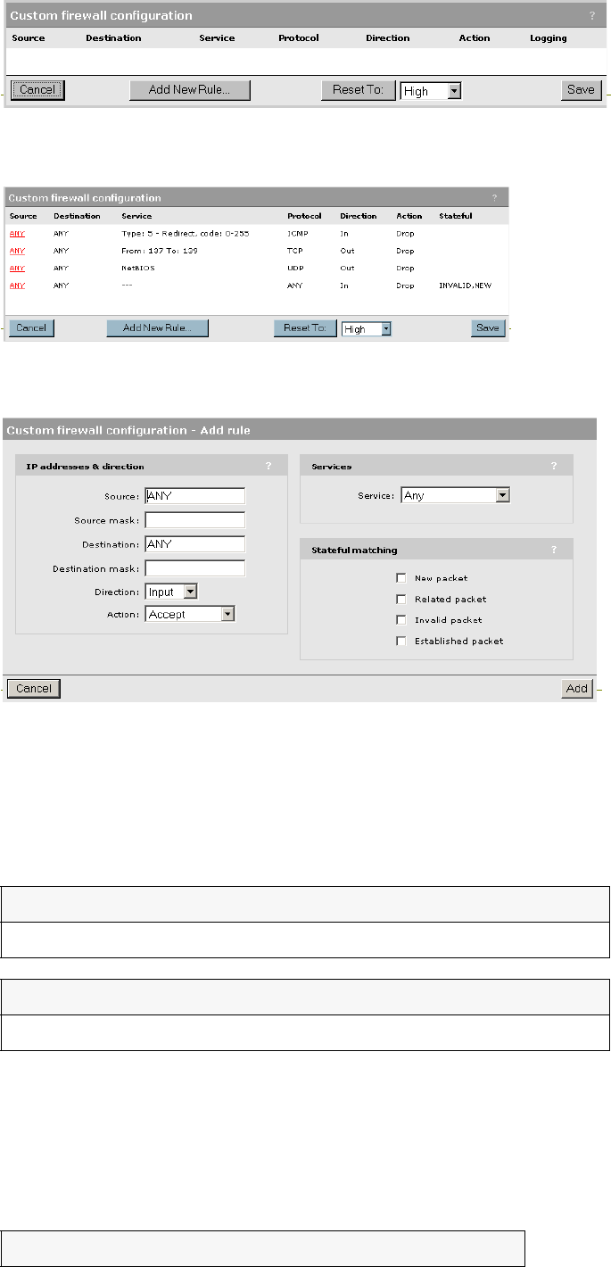
Chapter 8: Connecting to the Internet 86
DRAFT
3. Click Reset To High. This imports all the rules from the predefined high
security firewall.
4. Click the last rule to edit it. The Custom firewall configuration - Edit rule page
opens.
5.
6.
7.
8.
9. Remove the following rule.
10.
11.
To remove a rule, click the Source column to open the Custom firewall
configuration - Edit rule page and click Delete.
12. Add the following rules.
Source Destination Direction Action Service Port
ANY ANY Input Accept Any TCP 0 to 442
Source Destination Direction Action Service Port
ANY ANY Input Accept Any TCP 0 to 442
Source Destination Port Direction Service

Chapter 8: Connecting to the Internet 87
DRAFT
ANY ANY 0 to 79 In Any TCP
ANY ANY 81 to 442 In Any TCP
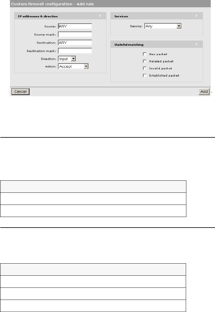
Chapter 8: Connecting to the Internet 88
DRAFT
13. To add a rule, click Add New Rule. The Custom firewall configuration - Add
rule page opens.
14. Fill in the appropriate fields and then click Add to save the rule and return to
the Custom firewall configuration page.
15. When done, click Save to activate the firewall.
Allowing FTP traffic
To run an FTP server on the internal network requires changes to the firewall,
similar to those done in the previous example. Follow the same steps, except in
step 5, add the following rules instead:
Allowing both Web and FTP traffic
If you intend to run both an Web and FTP server, follow the same steps
presented in the Web example, except in step 5, add the following rules instead:
Source Destination Direction Port Protocol
ANY ANY In 0 to 19 Any TCP
ANY ANY In 22 to 442 Any TCP
Source Destination Direction Port Protocol
ANY ANY In 0 to 19 Any TCP
ANY ANY In 22 to 79 Any TCP
ANY ANY In 81 to 442 Any TCP
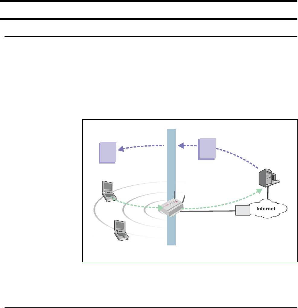
Chapter 8: Connecting to the Internet 89
DRAFT
Network address translation
NAT overview NAT is an address mapping service that enables one set of IP addresses to be
used on an internal network, while a second set is used on an external network.
NAT handles the mapping between the two sets of addresses.
Generally, NAT is used to map all the addresses on a internal network to a single
address for use on an external network like the Internet. The main benefits of this
are:
• It enables multiple devices to share a single connection.
• It effectively hides the IP addresses of all devices on the internal network from
the outside network.
NAT can also be useful in conjunction with VPN software. When two networks
are connected via a VPN tunnel, it may be desirable to obscure the address of
local computers for security reasons. NAT makes this possible.
NAT security and
static mappings
One of the benefits of NAT is that it effectively hides the IP addresses of all
computers on the internal network from the outside network (i.e., the Internet or a
remote site via VPN). While this is great for security, in some cases it is useful to
make a computer on the internal network accessible externally. For example, if
you want to run a Web server or FTP server.
To address this problem, NAT provides the ability to route specific incoming traffic
to an IP address on the internal network, through what is called a static NAT
mapping. For example, to support a Web server, you would define a static NAT
mapping to route traffic on TCP port 80 to an internal computer running a Web
server. Note that this may also require changes to the firewall settings to accept
the incoming traffic.
A limitation of NAT mappings is that they only allow one internal IP address to act
as the destination for a particular protocol (unless you map the protocol to a non-
standard port). This means, for example, that you can only run one Web server
on the internal network.
Web
server
Web Page Web Page
192.168.1.2
NAT
192.168.1.3
ISP
addressed to
192.168.1.2
addressed to
202.125.11.26
Internal addresses are invisible
to computers on the Internet.
All traffic uses the
same external IP
address assigned
by the ISP.
202.125.11.26
HTTP request

Chapter 8: Connecting to the Internet 90
DRAFT
Important: If you use NAT to enable a secure (HTTPS) Web server on the
internal network, remote access to the management tool will no longer be
possible, as all incoming HTTPS requests will be routed to the internal Web
server and not the management tool.
Important: NAT mappings bypass the firewall. If you create a static mapping, the
firewall is automatically opened to accept the traffic. However, this firewall rule
will not be visible on the Firewall configuration page.
The following table indicates how some common applications are affected by
NAT.
Most Web browsers execute FTP in active mode. Some browsers provide a
configuration option that enables you to alter this. For example, in Internet
Explorer choose Internet options on the Tools menu, click the Advanced tab,
and then under Browsing enable Use Passive FTP for compatibility with
some firewalls and DSL modems.
The CN3200 provides a list of preset settings for many commonly used
applications.
One-to-one NAT In its default configuration, NAT translates all internal IP address to a single
external one. This means that all client station sessions to an external resource
appear to originate from the same IP address. Certain applications do not allow
multiple connections from the same IP address, or impose a limit. For example:
some PPTP servers want a unique IP address for each client station.
To resolve this problem, the CN3200 allows you to assign multiple IP addresses
to the Internet port and use them to distinguish outgoing NAT traffic for customers
making VPN connections.
How it works
One-to-one NAT functions as follows:
•Define alternate static addresses for the Internet port on the Network > Ports
> Internet Port > Static page. These addresses must be valid on the Internet.
•Define the attribute “one-to-one-nat” in the RADIUS account for each customer
that requires a unique IP address. See “One-to-one NAT” on page 229 for
details.
•When a customer with one-to-one NAT support logs into the public access
interface and establishes a VPN session, the CN3200 reserves the next
available alternate IP address for that customer. If all alternate IP addresses
are in use, or none have been defined, then the default IP address of the
Internet port is used.
The address is reserved for as long as the customer is logged in and using a
VPN connection. Therefore, you need to define enough alternate IP addresses
to support the maximum number of active VPN sessions you expect to have at
any one time.
Application NAT Application NAT
FTP (passive mode) Mapping required Windows
networking
No effect
FTP (active mode) Mapping required NetMeeting Mapping required
Telnet Mapping required
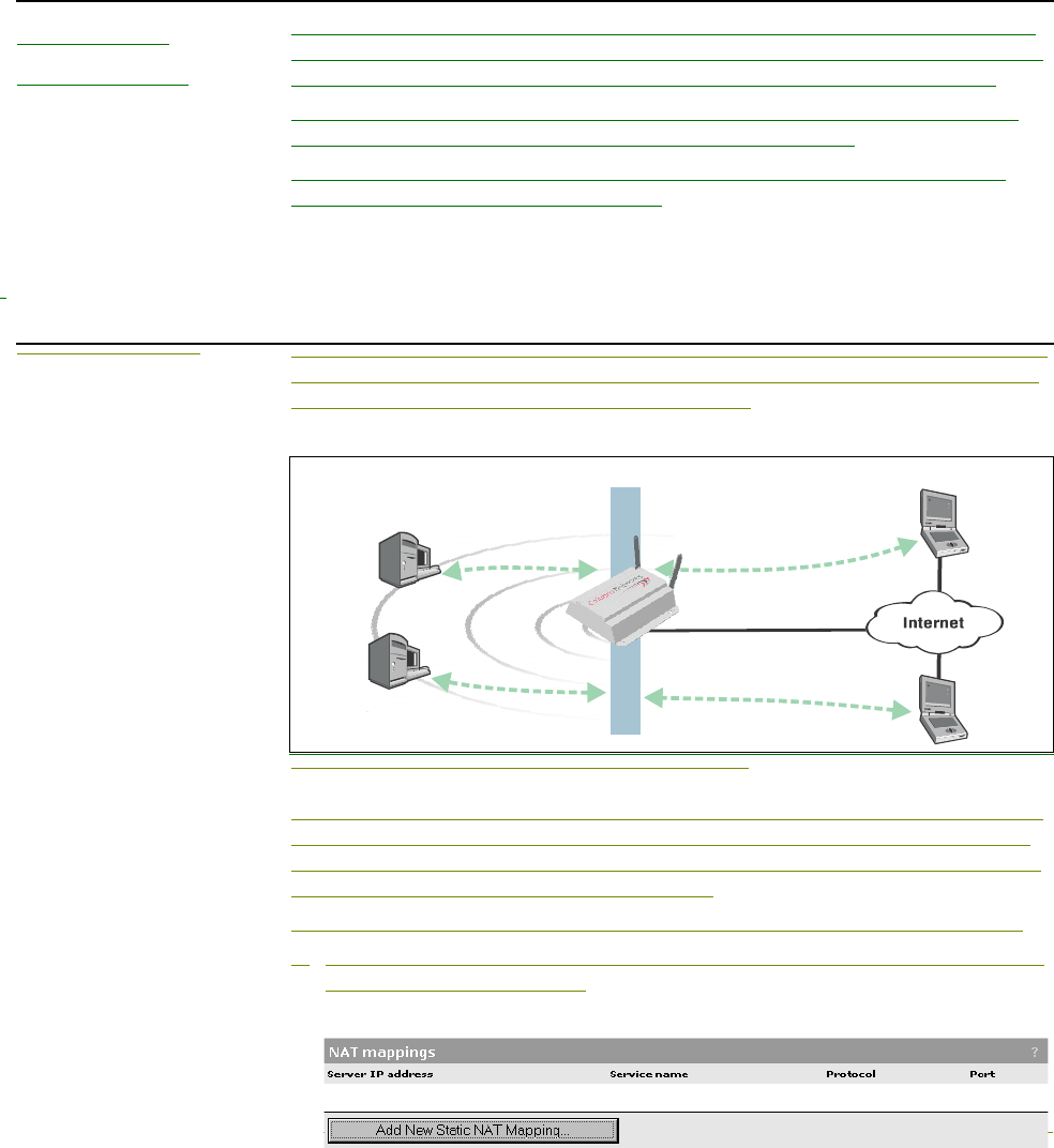
Chapter 8: Connecting to the Internet 91
DRAFT
NAT IPSec
passthrough
IPSec passthrough enables the CN3200 to support older IPSec clients that do
not support NAT traversal. These older IPSec clients are unable to establish an
IPSec connection through a gateway, like the CN3200, that is running NAT.
All recent IPSec clients support NAT traversal, so Colubris recommends that
IPSec passthrough be disabled unless specifically required.
Note: If you enables this option, it is possible that certain IPSec clients that
support NAT traversal may fail to work.
To disable this option go to the Network > Ports > Internet port page.
NAT example The following example illustrates how to configure static NAT mappings to run a
Web server and an FTP server on the internal network. This might occur when
the CN3200 is used in a enterprise environment.
NAT mapping used to support internal Web and FTP servers.
By creating static NAT mappings, FTP and HTTP (Web) traffic can be routed to
the proper client station. Note that the addresses of these stations are still not
visible externally. Remote computers send their requests to 202.125.11.26 and
the CN3200 routes them to the proper client.
To configure the CN3200 to support this example, you would do the following:
1. On the main menu, click Network, then click NAT. The NAT mappings page
appears. Initially it is empty.
Web
server
Web
browser
FTP
client
FTP
server
192.168.1.2
NAT
192.168.1.3
202.125.11.26
FTP traffic
Web (HTTP) traffic
192.168.1.1
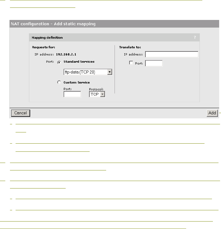
Chapter 8: Connecting to the Internet 92
DRAFT
2. Click Add New Static NAT Mapping. The NAT mappings - Add static
mapping page appears.
•Under Requests for, choose Standard Services, then choose http (TCP
80).
•Under Translate to, specify the IP address of the Web server. In the
example, it is 192.168.1.2.
3. Click Add to save your changes and return to the NAT mappings page. The
new mapping is added to the table.
4. To support the FTP server, two additional mappings need to be created with
the following values:
•Standard Services = ftp-data (TCP 20) and IP address = 192.168.1.3.
•Standard Services = ftp-control (TCP 21) and IP address = 192.168.1.3.
Depending on the firewall settings you are using, you may have to modify the
firewall to permit FTP and HTTP traffic to enter via the Internet port.

Chapter 9: Activating the public access interface 93
DRAFT
Chapter 9: Activating the public access interface
Chapter 9
Activating the public access interface
This chapter explains how to configure and start the public access
interface.
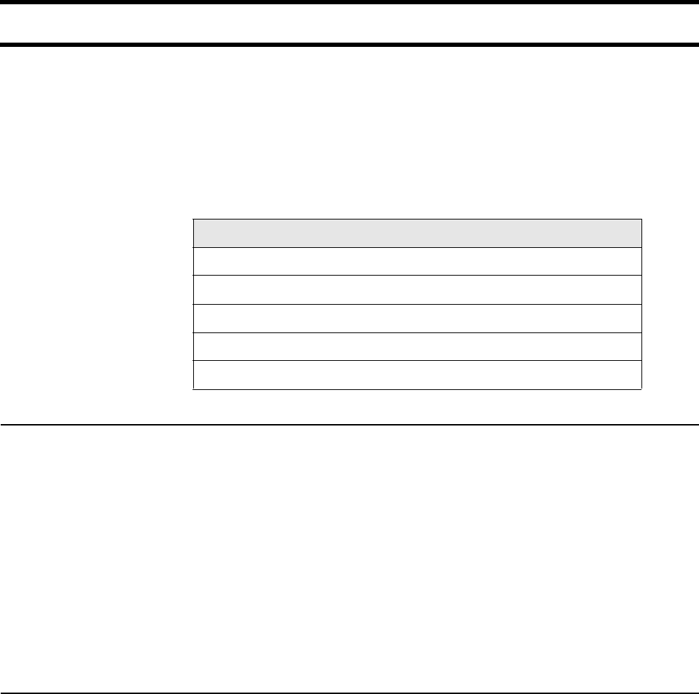
Chapter 9: Activating the public access interface 94
DRAFT
Overview
The public access interface is the sequence of web pages that customers use to
login, logout, and view the status of their wireless sessions. The CN3200 ships
with a default interface which you can customize to meet the needs of your
installation. However, before you do this, you should initialize the default setup
and test it with your network. Once the default interface is working, you can make
changes to it as described in Chapter 15.
This chapter presents the minimum tasks required to get the public access
interface working and enable customer authentication via a RADIUS server.
Important The CN3200 public access interface will not be functional until the CN3200
can successfully connect to a RADIUS server and authenticate itself. This
means that the login page for the public access interface will appear, but
customers will get an error when they try to log in. This applies regardless
of the method you are using to authenticate customers.
Until you define access lists (see page 216 for details) the following
conditions apply:
• Unauthenticated customers cannot reach any network resources other
than the CN3200 login page.
• Authenticated customers have access to any network resources
connected to the CN3200’s Internet port.
Supporting PDAs Customers using PDAs that only support a single browser window will have
difficulty using the public access interface in its standard configuration.
To solve this problem, see “Supporting PDAs” on page 172.
Task For instructions
Setting up the CN3200 RADIUS client See page 95.
Setting up CN3200 authentication See page 98.
Setting up customer authentication See page 100.
Setting up the RADIUS server See page 101.
Testing the public access interface See page 102.
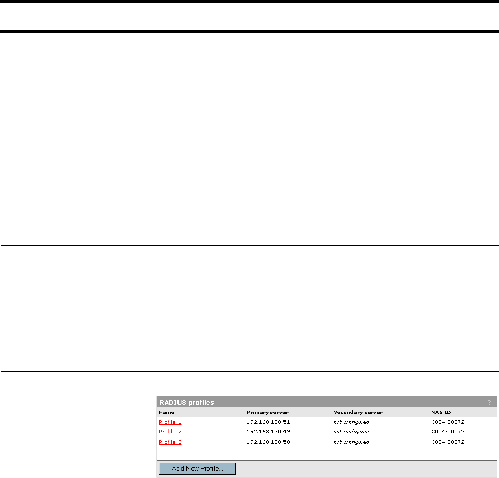
Chapter 9: Activating the public access interface 95
DRAFT
Step 1: Setting up the CN3200 RADIUS client
The CN3200 lets you define up to 16 RADIUS client profiles. Each profile defines
the settings for a RADIUS client connection. To support a client connection, you
must create a client account (sometimes called a RAS account) on the RADIUS
server. The settings for this account must match the profile settings you define on
the CN3200.
For backup redundancy, each profile supports a primary and secondary server.
The CN3200 will function with any RADIUS server that supports RFC 2865 and
RFC 2866. Authentication occurs via EAP-MD5, CHAP, MSCHAP v1/v2, or PAP.
Important: To safeguard the integrity of the customer accounts, it is important
that you protect communications between the CN3200 and the RADIUS server.
The CN3200 lets you use PPTP or IPSec to create a secure tunnel to the
RADIUS server. Refer to Chapter 10 for complete instructions on how to
accomplish this.
Managing shared
secrets
If you are installing multiple CN3200s, and you intend to use VPNs to secure the
connection each unit will establish with the RADIUS server, make sure that the
shared secret for each device is the same. This is required because there is no
way to guarantee that a specific CN3200 will receive a specific IP address when
connecting to the VPN server. Since the RADIUS server requires that you
associate an IP addresses with a secret, the only way to avoid problems is to use
the same secret for all CN3200s. The username and password assigned to each
CN3200 can be different, enabling you to differentiate between devices.
Configuration
procedure
1. Click Security, then click RADIUS. The RADIUS profiles list page opens.
2. Click Add New Profile. The RADIUS profile page opens.
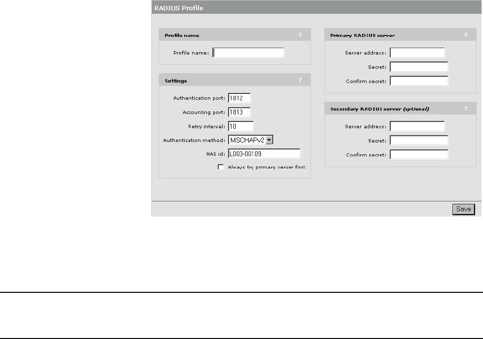
Chapter 9: Activating the public access interface 96
DRAFT
3. Configure the settings as required. Refer to the sections that follow for
detailed configuration information on each parameter.
4. Click Save when you are done.
Profile name Specify a name to identify the profile.
RADIUS profile
settings
Authentication port
Specify the port to use for authentication. By default, RADIUS servers use port
1812.
Accounting port
Specify the port to use for accounting. By default, RADIUS servers use port
1813.
Retry interval
Controls the retry interval (in seconds) for access and accounting requests that
time-out. If no reply is received within this interval, the CN3200 switches between
the primary and secondary RADIUS servers (if defined). If a reply is received
after the interval expires, it is ignored.
This parameter applies to access and accounting requests generated by the
following:
• administrator logins to the management tool
• customer logins via HTML
• MAC-based authentication of devices
• authentication of the CN3200
The maximum number of retries can be determined as follows:
• HTML-based logins: The number of retries is calculated by taking the setting
for HTML-based logins Authentication Timeout parameter and dividing it by the
value of this parameter. The default settings result in 4 retries (40 / 10).
• MAC-based and CN3200 authentication: Number of retries is infinite.
• 802.1x authentication. Retries are controlled by the 802.1x client software.

Chapter 9: Activating the public access interface 97
DRAFT
Authentication method
Choose the default authentication method the CN3200 will use when exchanging
authentication packets with the primary/secondary RADIUS server defined for
this profile.
For 802.1x users, the authentication method is always determined by the 802.1x
client software and is not controlled by this setting.
If traffic between the CN3200 and the RADIUS server is not protected by a VPN,
it is recommended that you use EAP-MD5 or MSCHAP V2 if supported by your
RADIUS Server. (PAP, MSCHAP V1 and CHAP are less secure protocols.)
NAS Id
Specify the network access server ID you want to use for the CN3200. By default,
the serial number of the CN3200 is used. The CN3200 includes the NAS-ID
attribute in all packets that it sends to the RADIUS server.
Always try primary server first
Set this option to force the CN3200 to contact the primary server first.
Otherwise, the CN3200 sends the first RADIUS access request to the last known
RADIUS server that replied to any previous RADIUS access request. If the
request times out, the next request is sent to the other RADIUS server if defined.
For example, assume that the primary RADIUS server was not reachable and
that the secondary server responded to the last RADIUS access request. When
a new authentication request is received, the CN3200 sends the first RADIUS
access request to the secondary RADIUS server.
If it does not reply, the RADIUS access request is retransmitted to the primary
RADIUS server. The CN3200 always alternates between the two servers, when
configured.
Primary RADIUS
server
Server address
Specify the IP address of the RADIUS server.
Secret/Confirm secret
Specify the secret (password) that CN3200 will use when communicating with
the RADIUS server. The shared secret is used to authenticate all packets
exchanged with the server to prove that they originate from a valid/trusted
source.
Secondary RADIUS
server
Server address
Specify the IP address of the RADIUS server.
Secret/Confirm secret
Specify the secret (password) that CN3200 will use when communicating with
the RADIUS server. The shared secret is used to authenticate all packets
exchanged with the server to prove that they originate from a valid/trusted
source.

Chapter 9: Activating the public access interface 98
DRAFT
Step 2: Setting up CN3200 authentication
Important: The CN3200 public access interface will not be functional until the
CN3200 can successfully connect to a RADIUS server and authenticate itself.
This means that the login page for the public access interface will appear, but
customers will get an error when they try to log in. This applies regardless of the
method you are using to authenticate customers.
The CN3200 authenticates itself to a RADIUS server each time:
• it is powered up
• it is restarted
• the authentication interval expires
At each authentication, the CN3200 can retrieve configuration information (if
defined), which includes settings such as:
• Access list defining the network resources unauthenticated customers have
access to.
• URLs specifying the location of any customized Web pages and their support
files.
• a URL specifying the location of a custom security certificate.
• a URL specifying the location of a configuration file.
• MAC addresses of devices to authenticate.
When you set up a profile for the CN3200 on the RADIUS server you define this
information in the form of a Colubris Networks vendor-specific attribute. See
“Creating a profile for the CN3200 on the RADIUS server” on page 214 for
details.
Configuration
procedure
1. Click Security, then click Authentication. The Authentication page opens.
2. Configure the settings for the CN3200 as required. Refer to the
“Configuration parameters” section that follows for detailed configuration
information on each parameter.
3. Click Save, when you are done.
4. If the profile for the CN3200 is configured on the RADIUS server, click the
Force authentication button. The red indicator will change to green if the
CN3200 successfully connects to the RADIUS server and is authenticated.
Configuration
parameters
RADIUS profile
Choose the RADIUS profile that will be used to authenticate the CN3200.
RADIUS username
Name of the RADIUS account assigned to the CN3200.
RADIUS password / Confirm password
Password of the RADIUS account assigned to the CN3200.
Authentication interval
The CN3200 will re-authenticate itself each time this interval expires. This
enables it to retrieve updated operating information at regular intervals.
To avoid potential service interruptions that may occur when new operating
information is activated by the CN3200, it is strongly recommended that a large
interval (12 hours or more) be used.
Chapter 9: Activating the public access interface 99
DRAFT
You can override this value using the RADIUS Attribute Session-timeout,
which enables the following effective strategy: Configure Authentication
interval to a small value (10 to 20 minutes) and set the RADIUS Attribute
Session-timeout to override it with a large value (12 hours) when
authentication is successful. Since the Authentication interval is also
respected for Access Reject packets, this configuration results in a short
re-authentication interval in the case of failure, and a long one in the case
of success.
Accounting
Enable this option to have the CN3200 generate a RADIUS accounting request
ON/OFF each time its authentication state changes.
Last authenticated
Indicates when the CN3200 was last successfully authenticated.
Force authentication
Click this button to force the CN3200 to authenticate now. This lets you test your
settings.
Advanced settings
Click this button to set additional authentication-related settings.

Chapter 9: Activating the public access interface 100
DRAFT
Step 3: Setting up customer authentication
The CN3200 uses the services of a RADIUS server to authenticate customer
logins, track and manage connection time, and generate billing information.
To login to the public access network, each customer must supply a username
and password. The CN3200 sends this information to the RADIUS server for
authentication. If the customer login is approved, the RADIUS server returns
configuration information for the customer. This includes settings for:
• Connection time limit for the customer’s session.
• Idle time limit for the customer’s session.
• Access list for the customer.
• Address of the e-mail server to use for redirection of the customer’s e-mail.
• URLs specifying the location of customized Welcome and Goodbye pages for
the customer.
When you set up a profile for a customer on the RADIUS server you define this
information in the form of a Colubris Networks vendor-specific attribute. See
“Creating customer profiles on the RADIUS server” on page 225 for details.
Configuration
procedure
1. On the main menu, click Security.
2. Click Authentication. The Authentications settings page opens.
3. Configure the settings for HTML-based user logins as defined below. This
controls the authentication procedure for customers who will login via the
public access interface on the CN3200.
4. Click Save, when you are done.

Chapter 9: Activating the public access interface 101
DRAFT
Step 4: Setting up the RADIUS server
To authenticate the CN3200 and its customers you must configure accounts on a
RADIUS server. The procedure for doing this varies depending on the RADIUS
server you are using. Consult the documentation that came with your RADIUS
server for details.
Minimum setup As a bare minimum you need to:
• Define RADIUS client settings for the CN3200
Any device that uses the authentication services of a RADIUS server is called
a RADIUS client. Therefore, each CN3200 is considered to be a RADIUS client
and you must define client settings for each one that you intend to install.
See page 213 for details.
• Create a RADIUS profile for the CN3200
Before it can activate the public access interface, the CN3200 must log onto a
RADIUS server and retrieve certain operating settings which you must define.
Therefore, you must create at least one RADIUS profile for use by the CN3200.
If you have multiple CN3200s, they can all be associated with a single RADIUS
profile.
See page 214 for details.
• Create a RADIUS profile for one or more customers
The customer profile is used to authenticate customers when they login and
store accounting information. It contains the settings that define the
characteristics of their account.
See page 225 for details.
More information For more information on configuring the RADIUS server, see:
•Chapter 16, which describes all the RADIUS configuration settings you can
define to customize the operation of the public access network and customer
accounts.
•Chapter 18, which provides a walkthrough of a sample RADIUS configuration
using Steel-belted Radius.
•Chapter 19, which provides a walkthrough of a sample RADIUS configuration
using Microsoft's RADIUS server: Internet Authentication Service.
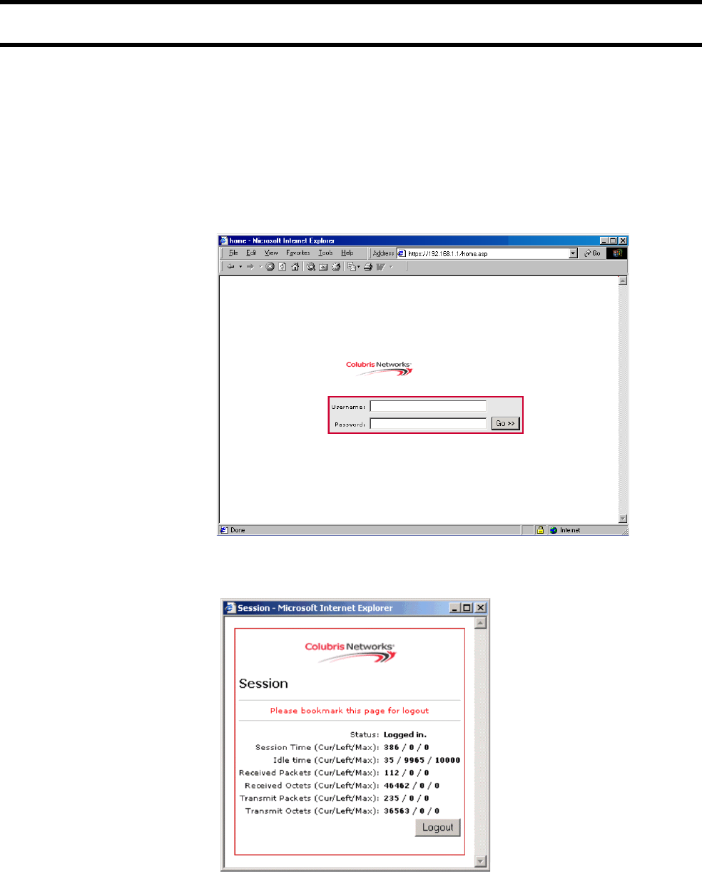
Chapter 9: Activating the public access interface 102
DRAFT
Step 5: Testing the public access interface
To test your installation, use a wireless client station to log onto the public access
interface. For this to work, the CN3200 must be configured as the client’s default
gateway.
1. Start the client station’s web browser and enter the IP address (or domain
name) of a web site on the Internet.
2. The CN3200 should intercept the URL and display the login page.
(Depending on the type of certificate that is installed on the CN3200, you may
see a security warning first.)
3. To login, specify a valid customer name and password. The CN3200 session
page should open.
4. Next, you are automatically redirected to the web site you originally
requested.

Chapter 10: Secure remote connectivity 103
DRAFT
Chapter 10: Secure remote connectivity
Chapter 10
Secure remote connectivity
This chapter explains how to establish secure connections to a remote
network.

Chapter 10: Secure remote connectivity 104
DRAFT
Secure remote connectivity using the PPTP client
The CN3200 features PPTP client software which enables it to create a secure
connection to a remote site via a non-secure infrastructure like the Internet.
PPTP works by creating a secure tunnel between two devices. Traffic in the
tunnel is protected against eavesdropping by means of encryption. Traffic in the
PPTP tunnel bypasses the CN3200’s firewall.
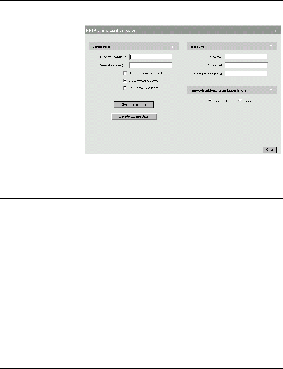
Chapter 10: Secure remote connectivity 105
DRAFT
Configuration
procedure
1. On the main menu, click Security.
2. Click PPTP client. The PPTP client configuration page opens.
3. Configure the settings required by your connection. Refer to the sections that
follow for detailed configuration information on each parameter.
4. Click Save, when you are done.
Connection PPTP server address
Specify the domain name or IP address of the PPTP server the CN3200 will
connect to.
Domain name(s)
Specify the domain name(s) of the PPTP server. Put a space between each
name as a separator. The CN3200 routes all traffic addressed to this domain
through the PPTP connection.
Auto-connect at start-up
Enable this option if you want the CN3200 to automatically establish the PPTP
connection when it restarts.
Auto-route discovery
Enable this option if you want the CN3200 to automatically discover and add
routes to IP addresses on the other side of the PPTP tunnel. The addresses
must be part of the specified domain. Routes are added only when an attempt is
made to access the addresses.
LCP echo
Certain VPN servers may terminate your connection if it is idle. If you enable this
option, the CN3200 will send a packet from time to time to keep the connection
alive.
Account Username
Specify the username the CN3200 will use to log on to the PPTP server. If you
are logging on to a Windows NT domain, specify: domain_name\username
Password / Confirm password
Specify the password the CN3200 will use to log on to the PPTP server.

Chapter 10: Secure remote connectivity 106
DRAFT
Network Address
Translation (NAT)
If you enable NAT, it effectively hides the addresses of all local computers so that
they are not visible on the other side of the PPTP connection.
If you disable NAT, then the appropriate IP routes must be added to send traffic
though the tunnel.
Note: This setting does not affect traffic on the Internet port.

Chapter 10: Secure remote connectivity 107
DRAFT
Secure remote connectivity using IPSec
IPSec provides the ability for two hosts (called peers in IPSec terminology) to
communicate in complete security over any IP-based network.
IPSec achieves this security though the use of sophisticated encryption that
makes it impossible for an eavesdropper to decode the packets of data being
exchanged between two IPSec peers.
The CN3200 supports IPSec on the Internet port. This enables you to use IPSec
to safeguard data exchanged with remote RADIUS servers,
Preconfigured
settings
The Internet Key Exchange protocol is used to negotiate IPSec security
associations. The negotiation is controlled by setting a number of different IKE
options. To simplify the configuration of IPSec, the CN3200 presets some of
these options, while others are automatically defined based on the needs of the
peer.
The following is a summary of the most important non-configurable IKE options:
Hash algorithm Accepts the algorithm proposed by the
peer. Supports MD5 and SHA-1.
Phase 2 encryption algorithm 3DES
Oakley group or
Diffie-Hellman
Accepts the group proposed by the peer.
Supports groups 2 and 5.
ID type and ID • If you enable Preshared key for
Authentication method, the CN3200
automatically sets:
ID type = IP address
ID = IP address assigned to the Internet
port.
To establish a security association the
peer must also set its IP type to IP
address.
• If you enable X.509 certificates for
Authentication method, the CN3200
automatically sets:
ID type = DER_ASN1_DN
ID = the distinguished name included in
the local certificate. The peer however
can use any of the four formats the
CN3200 supports: IP address, fully
qualified user name, fully qualified host
name, or DER_ASN1_DN.
Security association lifetimes • Phase 1: 6 hours
• Phase 2: 1 hour
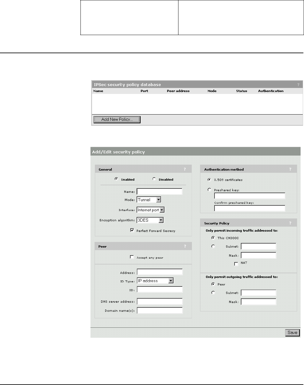
Chapter 10: Secure remote connectivity 108
DRAFT
Configuration
procedure
1. On the main menu, click Security.
2. Click IPSec. The IPSec security policy database page opens.
3. Click Add New Policy. The IPSec add/edit policy page opens.
4. Configure the settings required by your policy Refer to the sections that follow
for detailed configuration information on each parameter.
5. Click Save, when you are done.
General A security association can only be established between the CN3200 and a peer if
the policy is enabled.
Name
Specify a name for the policy. This identifies the policy in the IPSec security
policy database.
Perfect forward secrecy (PFS) New keying material will be generated for
each IPsec security association rather
than being derived from the ISAKMP SA
keying material.

Chapter 10: Secure remote connectivity 109
DRAFT
Mode
Choose the mode of operation. Two options are available.
• Tunnel mode: Use this mode if you want to create a secure tunnel to a remote
peer in order to transfer data between two networks (i.e. both peers are
operating as gateways). This option can also be used in peer-to-peer mode by
selecting the appropriate options for Incoming traffic and Outgoing traffic.
• Transport mode: This option creates a point-to-point connection to a remote
peer. Use this option if only the CN3200 needs to communicate with the remote
peer.
Interface
Select the port that the policy applies to.
Encryption algorithm
Select the encryption algorithm used for this policy.
• 3DES: Hardware accelerated
• AES/3DES: Will propose AES, If other side does not accept, then will switch to
3DES. AES is slower because no hardware acceleration is available. Should
be used for low-bandwidth (<1.5 Mb) connections.
Perfect Forward Secrecy
Enable this option to support automatic regeneration of keys. The key is changed
according to the following intervals:
• Phase 1 exchange: key changed every 6 hours
• Phase 2 exchange: key changed every 1 hour
Note: The CN3200 will negotiate times up to 24 hours as required by the peer.
Peer Accept any peer
(only available in tunnel mode)
Enable this option to permit the policy to accept an IPSec security association
from any peer. When this option is enabled, the CN3200 sets ID type and ID
automatically based on the selection for Authentication method. See IKE
options for more information.
Address
Specify the IP address or domain name of the peer.
ID type
Specify the method used to identify the peer.
IP address
• Specify the peer’s IP address. If you are using a Preshared key for
Authentication method, then you must use this option.
FQDN
Specify a fully qualified domain name. For example: gateway.colubris.com
user@FQDN
Specify a fully-qualified user name. For example: fred@colubris.com

Chapter 10: Secure remote connectivity 110
DRAFT
DER_ASN1_DN
Specify a distinguished name (DN) in LDAP (X.501) format. Enter a maximum of
91 characters. The following fields are supported.
Separate fields by a comma, space, or a forward slash (/). For example:
(CN=joe/E=joe@company.com/O=Company Inc./C=US)
ID
Specify an ID based on the ID type you selected. If you selected IP address, then
you can leave this field blank to use the address in the Address field.
DNS server address
Specify the domain name or IP address of the primary and secondary DNS
servers that the CN3200 will use to resolve DNS requests related to the remote
peer’s domain. In most cases these servers will be located on the network
protected by the peer.
Domain name
Specify the domain name of the peer. Any DNS requests on the wireless LAN for
addressed to this domain are forwarded to the DNS server specified above. This
enables the CN3200 to properly forward traffic to stations on the other side of an
IPSec tunnel.
Authentication
method
X.509 certificates
Select this option to use X.509 certificates to validate peers. To define certificate
settings, select certificates on the security menu.
Preshared key
Specify the key that will be used by the CN3200 to validate peers. The CN3200
and the peer must both use the same key.
Security Only permit incoming traffic addressed to
These settings enable you to filter incoming traffic so that only traffic addressed
to a specific network or network device is permitted from the peer. Note that the
setting you make for this parameter must match the setting the peer makes for
outgoing traffic. If not, the connection will not be established.
This CN3200
Only accepts incoming traffic that is addressed to the CN3200. All other traffic is
dropped.
Field Description
CN
SN
C
L
ST
O
OU
G
E
commonName
serialNumber
countryName
localityName
stateOrProvinceName
organizationName
organizationalUnitName
givenName
emailAddress
Chapter 10: Secure remote connectivity 111
DRAFT
Subnet
Mask
Only accepts incoming traffic that is addressed to the specified subnet or host
you specify. All other traffic is dropped. To accept all traffic from the peer, specify
both the Subnet and Mask as: 0.0.0.0
NAT
Enable network address translation for traffic addressed to the specified Subnet.
This hides the addresses of local computers from the peer. If you enable NAT, the
peer does not have to match the settings for Subnet.
Only permit outgoing traffic addressed to
These settings enable you to filter outgoing traffic so that only traffic addressed to
the peer, a specific network, or network device is sent. All other traffic is sent onto
the Internet outside the tunnel.
Note that the setting you make for this parameter must match the setting the peer
makes for incoming traffic. If not, the connection will not be established.
Peer
Only sends outgoing traffic that is addressed to the peer. All other traffic is sent
onto the Internet outside the tunnel.
Subnet
Mask
Only sends outgoing traffic that is addressed to the specified subnet or host you
specify. All other traffic is dropped. To send all outgoing traffic to the peer, specify
both the Subnet and Mask as: 0.0.0.0
Chapter 10: Secure remote connectivity 112
DRAFT

Chapter 11: Centralized architecture 113
DRAFT
Chapter 11: Centralized architecture
Chapter 11
Centralized architecture
This chapter explains how to create centralized management structures
for a variety of applications.
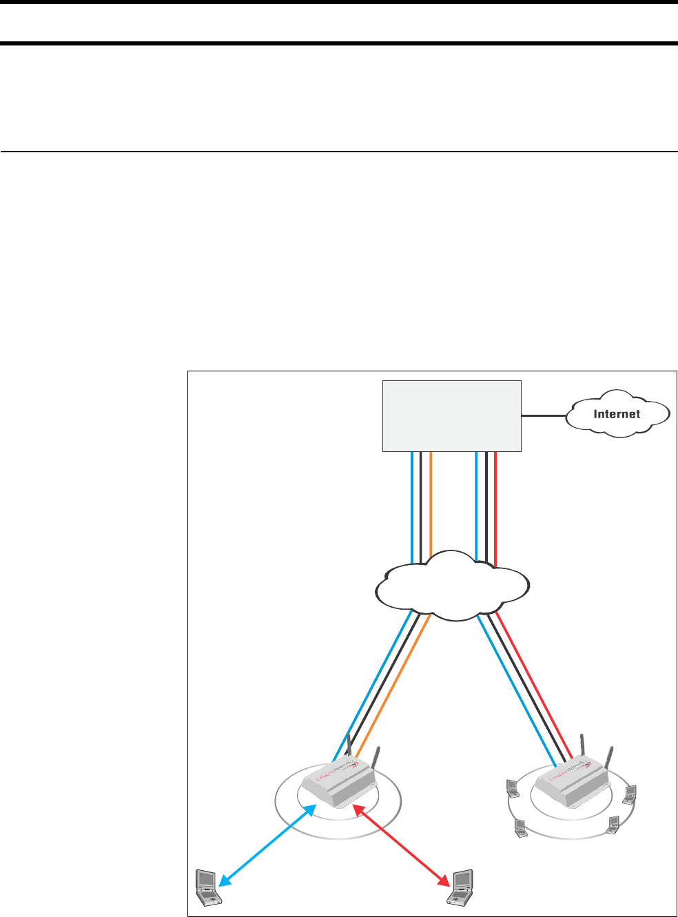
Chapter 11: Centralized architecture 114
DRAFT
Scenario #1: Centralized authentication
This scenario illustrates how to use GRE tunnels to move management of the
public access network to a centralized location that can be shared by multiple
geographically distributed access points.
How it works In this scenario, each CN3200 forwards all user traffic to a remote NOC. The
NOC is responsible for managing customer logins to the public access network
and granting access to the Internet.
This scenario supports two types of customers:
•Customers who login via an HTML session: Traffic for these customers is
routed through GRE tunnel #2, which is configured to handle all
unauthenticated wireless traffic. The CN3200 does no processing of this traffic.
•Customer who are using WPA or 802.1x: Login for these customers is
handled by the CN3200, which terminates the WPA or 802.1x session. The
CN3200 uses the services of the RADIUS server at the NOC to validate the
logins. Once authenticated, all customer traffic is sent in GRE tunnel #1.
P
U
B
L
I
C
W
L
A
N
P
U
B
L
I
C
W
L
A
N
CN3000 #1
GRE Tunnel #1
CN3000 #2
Private Broadband
Access Network
NOC
GRE Tunnel #2
GRE Tunnel #1
GRE Tunnel #2
WPA/802.1x
HTML Login
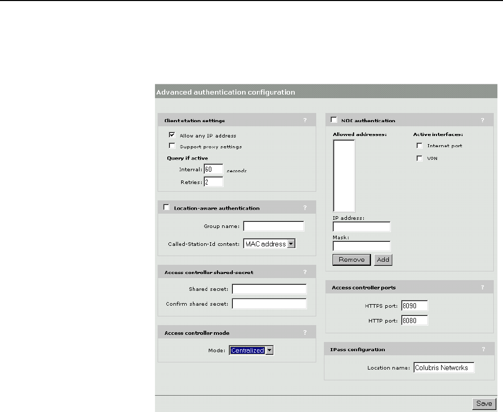
Chapter 11: Centralized architecture 115
DRAFT
Configuration
roadmap
The following configuration steps provide an overview on how to set up a
CN3200 to function in this scenario.
1. Open the Security > Authentication > Advanced page.
2. In the Access controller mode box, select Centralized and click Save. This
disables the public access interface on the CN3200.
3. Open the Network > GRE page, and add two GRE tunnels to the remote
NOC.
4. Open the Security > RADIUS page, and add a RADIUS profile that connects
to the RADIUS server on the NOC.
5. Open the Wireless > WLAN profiles page.
6. Click the Colubris Networks profile to edit it.
7. In the Traffic Tunneling (GRE) box, do the following:
• Map Authenticated 802.1x user traffic to GRE tunnel #1
• Map Unauthenticated user traffic to GRE tunnel #2.
8. In the Wireless protection box, enable either WPA or 802.1x and set it to
use the RADIUS profile you defined earlier.
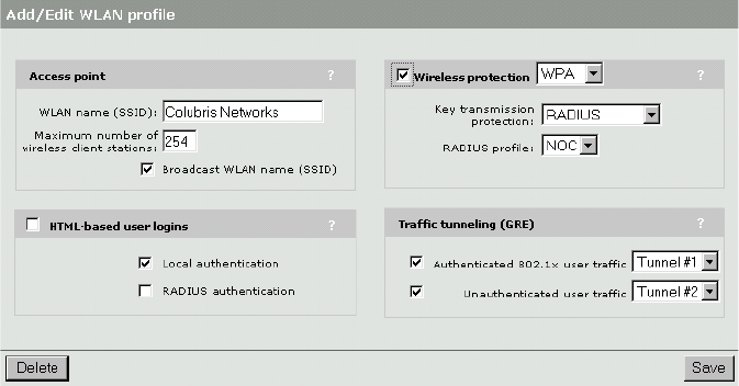
Chapter 11: Centralized architecture 116
DRAFT
9. Your settings should look like this when done:
10. Click Save.
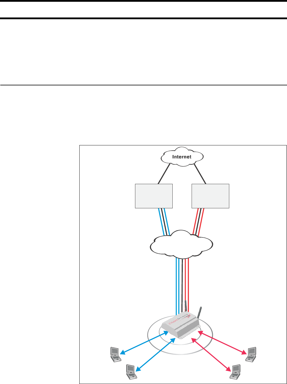
Chapter 11: Centralized architecture 117
DRAFT
Scenario #2: Wholesaling with GRE
This scenario illustrates how to use GRE tunnels and multiple SSIDs to share an
access point between more than one wireless Internet service provider (WISP).
This scenario assumes that one WISP is the owner of a private broadband
network and uses this network to link one or more CN3200s installed at different
locations. This WISP also owns the CN3200s and is responsible for managing
them. This WISP then leases out use of the access points to other WISPs.
How it works Each WISP provides their own NOC linked to the private broadband network.
The NOCs control customer logins to the public access network and granting
access to the Internet.
Each CN3200 is configured with two SSIDs for each WISP. The first is for
customers using HTML logins, and the second is for customers who are using
WPA or 802.1x. The two SSIDs are then each mapped to a specific GRE tunnel
that terminates at the appropriate NOC.
P
U
B
L
I
C
W
L
A
N
HTML Login
WISP #1
NOC
Private Broadband
Access Network
GRE Tunnels 1, 2
GRE Tunnels 3, 4
GRE Tunnels 1, 2
GRE Tunnels 3, 4
WPA/802.1x
Customers using
SSID #1
HTML Login
WPA/802.1x
Customers using
SSID #2
WISP #2
NOC

Chapter 11: Centralized architecture 118
DRAFT
Configuration
roadmap
The following configuration steps provide an overview on how to set up a
CN3200 to function in this scenario.
1. Open the Security > Authentication > Advanced page.
2. In the Access controller mode box, select Centralized and click Save. This
disables the public access interface on the CN3200.
3. Open the Network > GRE page, and add four GRE tunnels, two to each
remote NOC.
4. Open the Security > RADIUS page, and add a RADIUS profile that connects
to the RADIUS server on NOC 1. This is required for authentication of the
CN3200.
5. Open the Wireless > WLAN profiles page.
6. Define four profiles, two for each NOC.
•In the Traffic Tunneling (GRE) box, map authenticated and
unauthenticated user traffic to their own tunnels for each NOC.
•In the Wireless protection box, enable either WPA or 802.1x on one
profile for each NOC.
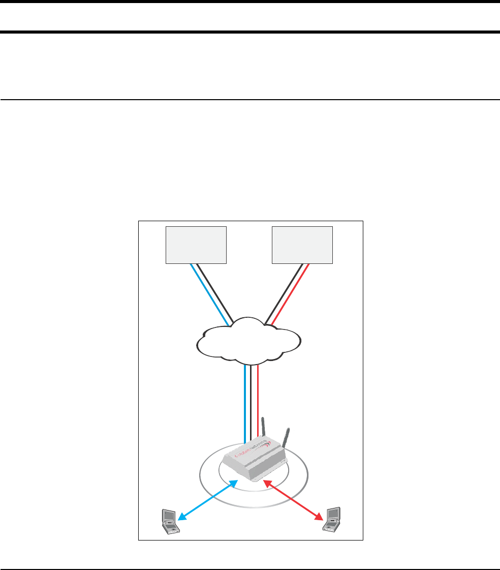
Chapter 11: Centralized architecture 119
DRAFT
Scenario #3: Wholesaling with VPNs
This scenario illustrates how to use IPSec and multiple SSIDs to share an access
point between multiple WISPs.
How it works In this scenario, the CN3200 controls access to the public access network. A
separate WLAN profile is defined for each WISP and is mapped to an IPSec
tunnel that terminates at the appropriate NOC. Each WISP must provide a
RADIUS server at the NOC to handle accounting and authentication duties. In
addition, a web server is required to host the customized public access interface.
Customers can choose which WISP to use by selecting the appropriate SSID
when they start their wireless client software.
In this scenario, all customers use HTML-based login.
Configuration
roadmap
The following configuration steps provide an overview on how to set up a
CN3200 to function in this scenario.
1. Open the Security > Authentication > Advanced page.
2. In the Access controller mode box, select Internal and click Save. This
enables the public access interface on the CN3200.
P
U
B
L
I
C
W
L
A
N
SSID #1
SSID #2
IPSec VPN #2
IPSec VPN #1
WISP #1
NOC
Internet
WISP #2
NOC
IPSec VPN #1 IPSec VPN #2
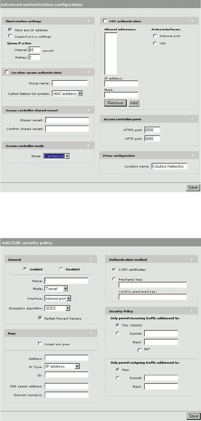
Chapter 11: Centralized architecture 120
DRAFT
3. Open the Security > IPSec page and add two security associations, one to
each remote NOC.
•Set Only permit outgoing traffic addressed to the IP address of the NOC
subnet.
Chapter 11: Centralized architecture 121
DRAFT
4. Open the Security > RADIUS page, and add two RADIUS profiles, one to
each remote NOC.
5. Open the Wireless > WLAN profiles page, add two WLAN profiles. Make
sure that each profile is mapped to the correct RADIUS profile.
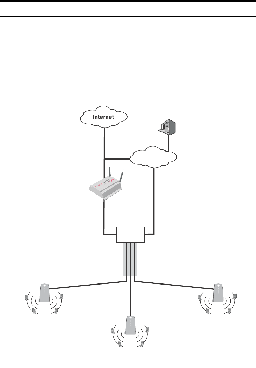
Chapter 11: Centralized architecture 122
DRAFT
Scenario 4: Public/private access with VLANs
This scenario illustrates how to use multiple SSIDs and VLANs to securely share
the wireless infrastructure between public and private users.
How it works In this scenario, the corporate network has four VLANs.
• VLANs 51, 52, 53 and 70 are assigned to the corporate Intranet and are used
by employees. VLAN carries authentication traffic to the RADIUS server.
• VLAN 60 is used by guests and is mapped to the CN3200. Access lists on the
CN3200 control the network resources guests can reach. For example, guests
can use the Internet and specific servers or printers on the corporate Intranet.
CN300
RADIUS server
VLAN 51, 52, 53, 70
802.1Q trunk
Corporate
Intranet
The Private WLAN has WPA support enabled
and is mapped to VLAN 70. Once users login,
their traffic is routed to VLAN 51, 52, or 53
according to the setting in their RADIUS account.
VLAN 60
Downstream port is
mapped to VLAN 60.
switch with
trunk port
Access controller
CN300CN300
CN3200
VLAN 70
The Public WLAN is not mapped to a VLAN,
and has no wireless protection enabled. All
traffic is forwarded onto the default VLAN of
60 that is assigned to the downstream port.
Public WLAN Private WLAN

Chapter 11: Centralized architecture 123
DRAFT
All CN300s have identical configurations as follows:
• Downstream port mapped to VLAN 60. This means that all traffic with no VLAN
assigned will be sent on VLAN 60 by default. Note that all management traffic
from the CN300s will use this VLAN and therefore be sent to the CN3200.
• Two SSIDs are defined:
• Public: This SSID is used by guests who login with their web browsers via the
CN3200’s public access interface. Guests accounts are stored on the
corporate RADIUS server. No VLAN is assigned to this SSID so all traffic is
assigned to VLAN 60 and is directed to the CN3200.
• Private: This SSID is used by employees to securely access the corporate
intranet. WPA is enabled on this SSID and it is mapped to VLAN 70. This
permits employees to reach the corporate RADIUS server for their logins to be
validated. Once authenticated, the RADIUS server assigns the employee with
a new VLAN based on settings in the employees RADIUS account. This
enables employees to be assigned either VLAN 51, 52, or 53 according to their
needs.
Configuration
roadmap
The following configuration steps provide an overview on how to set up a
CN3200 to function in this scenario.
On the CN3200
1. Open the Security > RADIUS page.
• Add a RADIUS profile that connects to the corporate RADIUS server.
2. Open the Security > Authentication page.
• In CN3000 authentication, define settings to connect to the corporate
RADIUS server via the profile you just added.
3. Open the Wireless > WLAN profiles page. Add Public.
• Add a profile named Public.
• Do not assign a VLAN to this profile.
• Enable HTML-based user logins and assign them to RADIUS
authentication.
4. Open the Security > Authentication > Advanced page and set the Access
controller shared secret.
5. Customize the public access interface as required. See Chapter 9 for details.
6. Define access lists to restrict the resources guests can reach. See for
“Access list” on page 229 details.
On the CN300s
1. Open the Wireless > WLAN profiles page. Add two profiles: Private and
Public.
• Private profile: in the Wireless protection box, enable either WPA or
802.1x.
2. Open the Network > Ports page.
• Enable DHCP client.
•Set VLAN to 60.
•Disable Restrict VLAN to management traffic only.

Chapter 11: Centralized architecture 124
DRAFT
3. Open the Security > Access controller page.
• Set the Access controller shared secret to same value as on the access
controller.
•Disable Location-aware authentication.
On the RADIUS server
Define the following:
1. Define accounts for the CN3000, guests, and employees.
2. In the employee account, setup support for VLAN mapping by defining the
following RADIUS attributes:
• Tunnel-type: Set to "VLAN".
• Tunnel-medium-type: Set to "802".
• Tunnel-private-group: Set to the VLAN number.
See “VLAN support” on page 231. for more information.

Chapter 12: Wireless bridging 125
DRAFT
Chapter 12
Chapter 12
Wireless bridging
This chapter explains how to use the wireless bridging feature to establish
links between access points.
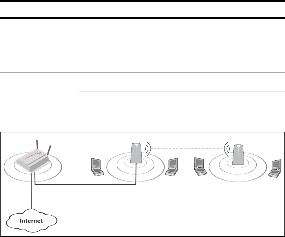
Chapter 12: Wireless bridging 126
DRAFT
Overview
The wireless bridging feature enables you to use the wireless radio to create
point-to-point wireless links to other access points.
Each CN3200 can support up to six wireless bridges, which can operate at the
same time as the network serving wireless customers.
Scenarios The following scenarios illustrate potential applications for wireless bridging.
RF extension
Wireless bridging provides an effective solution for extending wireless coverage
in situations where it may be impractical or expensive to install cabling to a
wireless access point. For example:
In this scenario, the two CN300s are used to expand the coverage of the wireless
network. The first CN300 is connected to the CN3200 via a backbone LAN. The
second CN300 uses the wireless bridging function to link with the first CN300.
P
U
B
L
I
C
W
L
A
N
P
U
B
L
I
C
W
L
A
N
P
U
B
L
I
C
W
L
A
N
CN3200
Backbone LAN
CN300 CN300
wireless bridge
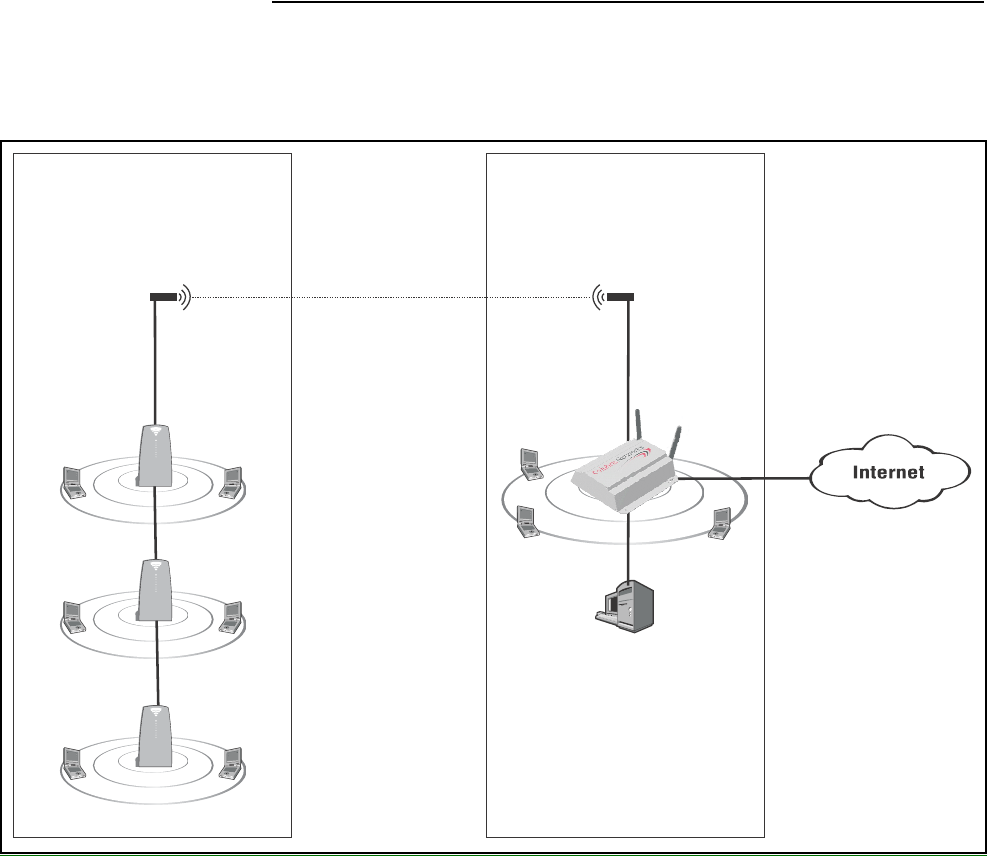
Chapter 12: Wireless bridging 127
DRAFT
Building-to-building connections
The CN3200s wireless bridging feature can also be used to create point-to-point
links over longer distances. For example, to create building-to-building
connections.
In this scenario, each CN3200 must be equipped with the appropriate external
antenna and be within line of sight to make the connection. Customers are
authenticated via the RADIUS server.
P
U
B
L
I
C
W
L
A
N
CN3200
P
U
B
L
I
C
W
L
A
N
CN300
wireless bridge
P
U
B
L
I
C
W
L
A
N
CN300
P
U
B
L
I
C
W
L
A
N
CN300
antenna antenna
Building A Building B
RADIUS
server
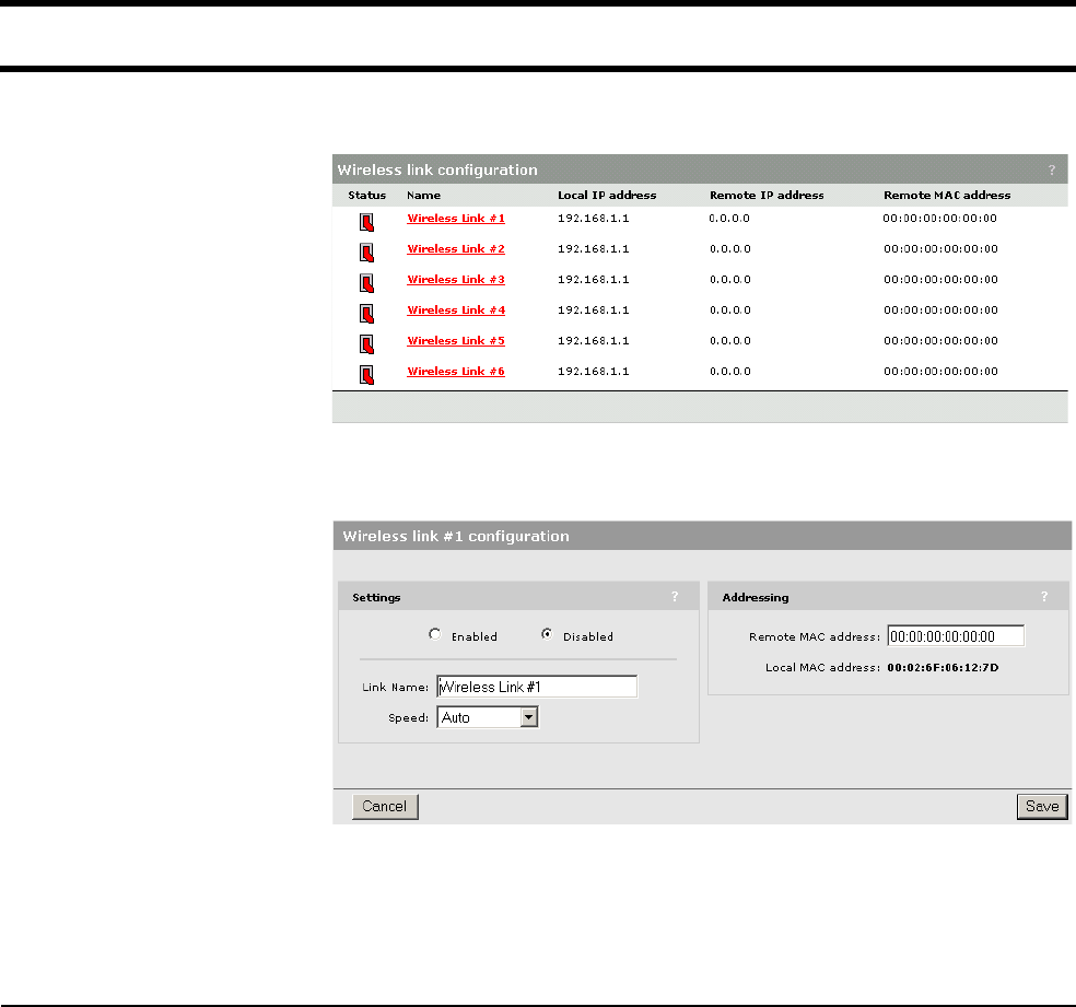
Chapter 12: Wireless bridging 128
DRAFT
Setting up a wireless link
1. On the Wireless menu, click Wireless links. The Wireless links page opens.
2. Click the wireless link you want to configure. The configuration page for the
link opens.
3. In the Settings box, select Enabled.
4. In the Addressing box, specify the MAC address of the other access point.
5. Click Save.
Wireless link
status
To view the status of the wireless links, open the Status > Wireless page.

Chapter 13: SNMP interface 129
DRAFT
Chapter 13: SNMP interface
Chapter 13
SNMP interface
This chapter provides an overview of the SNMP interface and the MIBs
supported by the CN3200.
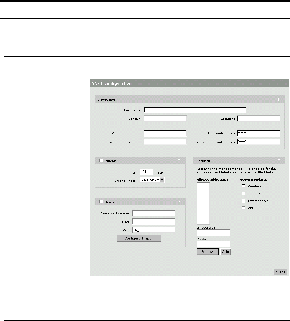
Chapter 13: SNMP interface 130
DRAFT
Configuring the SNMP interface
The CN3200 SNMP interface can be reached both locally and remotely for
complete flexibility.
To configure
SNMP options
1. On the main menu, click Management, then click SNMP. The SNMP
configuration page opens.
2. Enable the options that you require. The options are described in the sections
that follow.
3. Click Save.
Attributes System name
Specify a name to identify the CN3200.
Contact
Contact information for the CN3200.
Location
Location where the CN3200 is installed.
Community name
This is the password that controls access to the SNMP information. A network
management program must supply this password when attempting to set or get
SNMP information from the CN3200.

Chapter 13: SNMP interface 131
DRAFT
Read-only community name
This is the password that controls read-only access to the SNMP information. A
network management program must supply this password when attempting to
get SNMP information from the CN3200.
Agent Enables/disables support for SNMP.
Port
Specify the port and protocol the CN3200 will use to respond to SNMP requests.
Default port is 161.
SNMP protocol
Specify the SNMP version.
Traps Enables/disables support for SNMP traps.The CN3200 supports the following
MIB II traps:
•coldStart
• linkUp
• linkDown
• authenticationFailure
In addition, the CN3200 supports a number of Colubris-specific traps as
described in the Colubris Enterprise MIB. The Colubris Enterprise MIB is
available on the Colubris Networks web site.
Community name
Specify the password required by the remote host that will receive the trap.
Host
Specify the IP address or domain name of the host that the CN3200 will send
traps to.
Port
Specify the port that the CN3200 will send traps on. By default, port 162 is used.
Configure Traps
Click this button to customize certain traps.
Security Allowed addresses
Lets you define a list of IP address from which access to the SNMP interface is
permitted. To add an entry specify the IP address and appropriate mask and click
Add.
When the list is empty, access is permitted from any IP address.
Active interfaces
Choose the interfaces through which client stations will be able to access the
SNMP interface.

Chapter 13: SNMP interface 132
DRAFT
Standard MIBs
The CN3200 supports the following MIBs:
• IEEE8021-PAE-MIB
• RFC1213-MIB
Full read support. Write support as defined below.
•RIPv2-MIB
•802.11b
The MIB defined in "IEEE Std 802.11b/D8.0, September 2001 Annex D" has
been moved under the Colubris Enterprise MIB (COLUBRIS-IEEE802DOT11).
• Colubris Enterprise MIB (Discussed in detail later in this chapter.)
Management
consoles
To manage the CN3200, third-party SNMP management consoles must support
the SNMPV2C protocol.
MIB II support
details
The CN3200 provides complete read support of MIB II objects 1.10. The
following table lists all MIB II objects defined as read/write and indicates the
objects that can be “set” on the CN3200.
Set Group OID Notes
Y system sysContact
YSysName
Y sysLocation
Y interfaces ifAdminStatus(1) Can be up(1), down(2), or
testing(3).
N At AtIfIndex
NatPhysAddress
N atNetAddress
NIpipForwarding
N ipDefaultTTL
N ipRouteDest
N ipRouteIfIndex
NiprouteMetric1
NiprouteMetric2
NiprouteMetric3
NiprouteMetric4
N ipRouteNextHop
N ipRouteType (3) Can be other(1), invalid(2),
direct(3), or indirect(4).

Chapter 13: SNMP interface 133
DRAFT
N ipRouteAge
N ipRouteMask
N ipRouteMetric5
N ipNetToMediaIfIndex
N ipNetToMediaNetAddress
N ipNetToMediaType(4) Can be other(1), invalid(2),
dynamic(3), or static(4).
N Tcp tcpConnState(5) Can be closed(1), listen(2),
synSent(3), synReceived(4),
established(5), finWait1(6),
finWait2(7), closeWait(8),
lastAck(9), closing(10),
timeWait(11), or deleteTCB(12).
Set Group OID Notes

Chapter 13: SNMP interface 134
DRAFT
Colubris Enterprise MIB
The Colubris Enterprise MIB is available on the Colubris Networks web site. It is
organized as follows:
• COLUBRIS-CDP-MIB
•COLUBRIS-IEEE802DOT11
• COLUBRIS-MAINTENANCE-MIB
• COLUBRIS-PRODUCTS-MIB
• COLUBRIS-SMI (Glue between standard tree and Colubris Enterprise MIB.)
• COLUBRIS-SYSLOG-MIB
• COLUBRIS-SYSTEM-MIB
• COLUBRIS-TC (Contains Colubris textual conventions.)

Chapter 13: SNMP interface 135
DRAFT
COLUBRIS-IEEE802DOT11 MIB details
Group OID Get Set
dot11StationConfig
dot11StationId N N
dot11MediumOccupancyLimit N N
dot11CFPPeriod N N
dot11CFPMaxDuration N N
dot11AuthenticationResponseTimeOut N N
dot11PowerManagementMode N N
dot11DesiredSSID N N
dot11DesiredBSSType N N
dot11OperationalRateSet N N
dot11BeaconPeriod Y N
dot11DTIMPeriod Y N
dot11AssociationResponseTimeOut N N
dot11PrivacyOptionImplemented Y N
dot11AuthenticationAlgorithms
dot11AuthenticationAlgorithmsEnable Y N
dot11WEPDefaultKeys
dot11WEPDefaultKeyValue Y Y
dot11WEPKeyMappings
dot11WEPKeyMappingAddress N N
dot11WEPKeyMappingWEPOn N N
dot11WEPKeyMappingValue N N
dot11WEPKeyMappingStatus N N
dot11Privacy
dot11PrivacyInvoked Y Y
dot11WEPDefaultKeyID Y Y
dot11WEPKeyMappingLength N N
dot11ExcludeUnencrypted Y Y
dot11SMTnotification N N

Chapter 13: SNMP interface 136
DRAFT
Group OID Get Set
dot11Operation
Dot11RTSThreshold Y Y
Dot11ShortRetryLimit Y N
Dot11LongRetryLimit Y N
Dot11FragmentationThreshold Y N
Dot11MaxTransmitMSDULifetime Y N
Dot11MaxReceiveLifetime Y N
dot11Counters Y N
Group OID
dot11GroupAddresses
Dot11Address N N
Dot11GroupAddressesStatus N N
dot11PhyOperation
Dot11CurrentRegDomain Y N
dot11PhyAntenna
Dot11CurrentTxAntenna Y N
Dot11CurrentRxAntenna Y N
dot11PhyTxPower
Dot11CurrentTxPowerLevel Y N
dot11PhyFHSS
Dot11CurrentChannelNumber N N
Dot11CurrentDwellTime N N
Dot11CurrentSet N N
Dot11CurrentPattern N N
Dot11CurrentIndex N N
dot11PhyDSSS
Dot11CurrentChannel Y Y
Dot11CurrentCCAMode Y N
Dot11EDThreshold Y N
dot11PhyIR
Dot11CCAWatchdogTimerMax N N
Dot11CCAWatchdogCountMax N N
Dot11CCAWatchdogTimerMin N N
Dot11CCAWatchdogCountMin N N

Chapter 13: SNMP interface 137
DRAFT
Traps
Not applicable.
dot11RegDomainsSupported Y N
dot11AntennasList
Dot11SupportedTxAntenna Y N
Dot11SupportedRxAntenna Y N
Dot11DiversitySelectionRx Y N
SupportedDataRatesTx Y N
SupportedDataRatesRx Y N
Group OID Get Set
Chapter 13: SNMP interface 138
DRAFT

Chapter 14: SSL certificates 139
DRAFT
Chapter 14: SSL certificates
Chapter 14
SSL certificates
This chapter explains how to create and install SSL certificates to secure
communications with the CN3200.

Chapter 14: SSL certificates 140
DRAFT
Overview of SSL certificates
The only way to securely access a web server is to encrypt the data stream that
is exchanged between the browser and the web server. This ensures that if data
is intercepted by a malicious third-party using a network analyzer on the LAN or
the Internet, it will be difficult or impossible for the data to be deciphered.
However, encryption does not solve another important security issue, namely
how the identity of a web server can be validated before a connection to it is
established. The solution to this problem is provided by digital certificates.
A digital certificate is a collection of information about a web server, digitally
signed by a certificate authority. A certificate authority is by definition an entity
that can be trusted. It may be an entity in your organization responsible for
issuing certificates, a commercial certificate authority such as Thawte or Entrust,
or even yourself.
SSL is the standard for creating a secure encrypted connection between a web
browser and a web server. SSL relies on the exchange of digital certificates,
which provide the means for the web server and browser to authenticate each
other.
SSL
authentication
The following sequence of steps illustrates how an SSL session is established.
1. A web browser attempts to open a web page via HTTPS.
2. The web server sends its digital certificate (as well as information needed to
establish the SSL connection) to the web browser. The certificate is signed
using the private key of a certificate authority (CA). This is usually a well-
known commercial entity.
3. The web browser attempts to validate the web server’s certificate. This occurs
as follows:
• The web browser checks that the server’s certificate has not expired. The
certificate will contain the certificate’s validity period which can be
compared to the current date.
• The web browser may be configured to check that the certificate is not in a
Certificate Revocation List maintained by the entity that issued the
certificate.
• The web browser checks its internal list of trusted CAs to find the one that
signed the web server’s certificate. Using the public key of this CA (which is
also stored in the web browser), the web browser validates the authenticity
of the web server’s digital signature. This is possible because the web
server’s certificate is signed using the CA’s private key.
• The web browser extracts the domain name of the web server from the
certificate. (When the certificate was registered, this domain name was
associated with the IP address of the CN3200’s Internet port.) It then
compares this against the domain name of the web server.
4. The web browser and the web server agree on a symmetric key to encrypt
the SSL connection.
5. The SSL connection is started.
The host name in the currently installed SSL certificate is automatically assigned
as the domain name of the CN3200. The factory default SSL certificate that is
installed on the CN3200 has the host name wireless.colubris.com.

Chapter 14: SSL certificates 141
DRAFT
You do not have to add this name to your DNS server for it to be resolved. The
CNx intercepts all DNS requests it receives on the wireless or LAN ports. It
resolves any request that matches the certificate host name by returning the IP
address assigned to the Internet port. All other DNS requests are forwarded to
the appropriate DNS servers as configured on the Network > DNS/WINS page.
To summarize, this means that by default, any DNS request by a client station on
the wireless or LAN ports that matches wireless.colubris.com will return the IP
address of the CN3200’s Internet port.
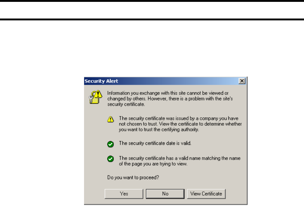
Chapter 14: SSL certificates 142
DRAFT
Eliminating certificate warning messages
The default certificate installed on the CN3200 is not registered with a certificate
authority. It is a self-signed certificate which is attached to the default IP address
(192.168.1.1) for the CN3200.
This results in the following warning message each time a web browser attempts
to validate the certificate:
There are three (3) types of possible warnings in the Security Alert:
1. The security certificate was issued by a company you have not chosen to
trust.
This indicates that your browser has no knowledge of the certificate and
treats it as if it cannot be trusted. The is caused by not having a CA certificate
in the browser that can validate the certificate provided by the CN3200.
To eliminate this warning message, you can:
• Replace the default certificate on the CN3200 with a certificate registered
with a known certificate authority.
• Install a self-signed certificate on the CN3200 and install a matching Root
CA certificate in the browsers for all client stations.
For instructions, see “Creating an SSL certificate” on page 143.
2. The Security certificate date is valid.
Signifies that the operating system's date is within the range of beginning and
end dates specified in the security certificate. Certificates have a limited
lifetime and must be renewed and replaced before they expire or else
warnings will appear in the browser.
3. The security certificate has a valid name.
This refers to the domain name listed in the "subject" field of the security
certificate that matches the domain name of the URL that you're attempting to
go to. By default the name in the "subject" field of the certificate installed in
the CN3000 also becomes the domain name of the CN3000 and is resolved
by the CN3000 itself.

Chapter 14: SSL certificates 143
DRAFT
Creating an SSL certificate
The are three ways to create a digital certificate:
• Obtain a registered certificate from a recognized certificate authority: This is
the best option, since it ensures that your certificate can be validated by any
web browser. A number of companies offer this service for a nominal charge.
These include: Thawte, Verisign, and Entrust.
• Become a CA and issue your own certificate: You can become your own CA.
and create as many certificates as you require. However, since your CA will not
be included in the internal list of trusted CAs maintained by most browsers,
customers will get a security alert until they add your CA to their browser.
• Create a self-signed certificate: This is the least secure method, since the
certificate is signed using the private key of the server rather than a CA. Self-
signed certificates should generally be used for testing purposes only.
Certificate tools Digital certificates can be created/managed with a variety of tools. The examples
in this chapter use the OpenSSL tools and components included with the
Colubris Backend archive. You should download and install these items as
follows:
1. Download Backend_v.1.22.zip from www.colubris.com > download >
CN3000.
2. Download openssl-0.9.7a-win32-bin.zip from http://curl.haxx.se/
download.html > OpenSSL Library Packages.
3. Open a command prompt and create the following folder on your computer:
c:\certificates and c:\certificates\newcerts
4. Extract openssl-0.9.7a-win32-bin.zip into c:\certificates.
5. Extract the contents of the certificates folder in the Backend_v.1.22.zip into
c:\certificates.
You are now ready to execute the following examples.
Obtaining a
registered
certificate
This example illustrates how to create a certificate request and send it to a
certificate authority to obtain a registered public certificate.
The benefit of using a registered certificate is that the public key for these CAs is
included by default in most web browsers, eliminating warning messages.
For the purposes of this example:
• the certificate will be requested for the domain name: www.company.com
• the secret password used to protect the key is your_password
1. Open a Windows command-line session.
2. Go to the directory where you installed the certificate tools. This example
assumes c:\certificates.
3. Execute the command: newreq domain_name
For example:
C:\certificates\>newreq www.company.com
You will now be prompted for a password
that will protect the new private key.
Loading 'screen' into random state - done
0 semi-random bytes loaded
Chapter 14: SSL certificates 144
DRAFT
Generating RSA private key, 1024 bit long modulus
....................................++++++
..................................++++++
e is 65537 (0x10001)
Enter pass phrase: your_password
At this stage, the private key has been generated and you are prompted
to specify the secret password that will protect the key. Do not forget
this password, otherwise you will loose access to the private key.
From this point on, this password will be referred to as the key
password.
When prompted, enter the password again to confirm it.
Verifying password - Enter PEM pass phrase: your_password
Re-enter the password for your new private key
(The same you just entered)
Enter pass phrase for www.company.com.key: your_password
You are about to be asked to enter information that will be incorporated
into your certificate request.
What you are about to enter is what is called a Distinguished Name or a
DN.
There are quite a few fields but you can leave some blank
For some fields there will be a default value,
If you enter '.', the field will be left blank.
-----
Country Name (2 letter code) [CA]:
State or Province Name (full name) [Quebec]:
Locality Name (eg, city) [Laval]:
Organization Name (eg, company) [Colubris Networks Inc.]:Company Inc.
Organizational Unit Name (eg, section) [Research &
Development]:Department
Your Name []:www.company.com
Email Address [support@colubris.com]:support@company.com
Generated certificate request:
Using configuration from openssl.conf
Certificate Request:
Data:
Version: 0 (0x0)
Subject: C=CA, ST=Quebec, L=Laval, O=Company Inc.,
OU=Department, CN=www
.company.com/Email=support@company.com
Subject Public Key Info:
Public Key Algorithm: rsaEncryption
RSA Public Key: (1024 bit)
Modulus (1024 bit):
00:cb:bb:24:82:9d:f6:24:ee:8f:f4:ec:39:5c:88:
a2:c3:08:96:68:1b:0b:c8:a8:48:09:db:6f:01:c2:
45:41:d0:a4:eb:b0:11:78:3d:55:ea:49:26:e1:dc:
9a:02:79:ae:fc:2c:4a:8a:d7:d7:eb:50:49:ec:08:
d3:7b:fe:66:52:fd:74:0a:9d:f4:e1:79:95:3a:7f:
46:d6:79:ea:04:7c:63:1b:36:9c:c2:28:4f:1a:01:
9a:90:90:6f:7c:f3:b4:d7:0d:d5:9d:e0:bf:b3:af:
b9:8a:95:6a:87:20:0b:e8:28:29:03:cb:1d:54:9f:
6d:c5:67:d6:1d:6b:9a:08:4b
Exponent: 65537 (0x10001)
Attributes:
a0:00
Signature Algorithm: md5WithRSAEncryption
a5:53:2d:91:95:1f:9c:75:ac:0e:92:1d:b9:7f:b2:c3:ce:59:
ca:aa:fc:1c:e2:f2:09:a9:bf:1d:34:ae:a9:ac:44:6a:d8:7e:
ac:de:9e:ed:00:d9:57:e0:bf:c9:c1:a6:25:ba:d6:68:a8:24:
d5:05:94:03:c8:54:49:cd:db:a6:d4:87:29:c5:ab:0e:59:30:
01:f9:d0:f8:0e:75:c5:39:38:0c:77:e3:87:ab:6d:25:3f:fd:
d5:a6:08:0a:02:0c:67:6d:84:bb:2b:3e:d8:b3:2c:08:1d:38:
53:a7:61:00:7a:91:67:16:03:6a:51:0b:67:db:73:4c:4d:96:
bf:80
-----BEGIN CERTIFICATE REQUEST-----
MIIB2TCCAUICAQAwgZgxCzAJBgNVBAYTAkNBMQ8wDQYDVQQIEwZRdWViZWMxDjAM
BgNVBAcTBUxhdmFsMRUwEwYDVQQKEwxDb21wYW55IEluYy4xEzARBgNVBAsTCkRl
cGFydG1lbnQxGDAWBgNVBAMTD3d3dy5jb21wYW55LmNvbTEiMCAGCSqGSIb3DQEJ
ARYTc3VwcG9ydEBjb21wYW55LmNvbTCBnzANBgkqhkiG9w0BAQEFAAOBjQAwgYkC
gYEAy7skgp32JO6P9Ow5XIiiwwiWaBsLyKhICdtvAcJFQdCk67AReD1V6kkm4dya
Anmu/CxKitfX61BJ7AjTe/5mUv10Cp304XmVOn9G1nnqBHxjGzacwihPGgGakJBv
fPO01w3VneC/s6+5ipVqhyAL6CgpA8sdVJ9txWfWHWuaCEsCAwEAAaAAMA0GCSqG
SIb3DQEBBAUAA4GBAKVTLZGVH5x1rA6SHbl/ssPOWcqq/Bzi8gmpvx00rqmsRGrY
fqzenu0A2Vfgv8nBpiW61mioJNUFlAPIVEnN26bUhynFqw5ZMAH50PgOdcU5OAx3
44erbSU//dWmCAoCDGdthLsrPtizLAgdOFOnYQB6kWcWA2pRC2fbc0xNlr+A
-----END CERTIFICATE REQUEST-----
At this stage, two files have been created in c:\certificates:
•www.company.com.key: This file contains the private key for the server.
•www.company.com.req: This file contains the certificate request which
you send to a Trusted Certificate Authority to obtain a public key certificate

Chapter 14: SSL certificates 145
DRAFT
from the CA of your choice. The certificate file will be protected by the
password you specified.
You
Becoming a CA This procedure enables you to sign your web server certificates using your own
private key. Customers who trust you will be able to trust the certificates you have
signed, providing that they have your public key certificate.
Creating the CA certificates
You will be asked for a password to protect the new private key, which will be the
private key for your own Certificate Authority.
Important: This password will be required when signing subsequent certificates.
Ideally, the private key should be handled as one of your corporate secrets and
should be in a safe location accessible to the person responsible for signing the
certificates.
For the purposes of this example:
• the certificate will be requested for the domain name: CompanyCA
• the secret password used to protect the key is CA_key_password
1. Open a Windows command-line session.
2. Go to the directory where you installed the certificate tools. This example
assumes c:\certificates.
3. Execute the command: newca CompanyCA
C:\certificates\DemoCA>newca CompanyCA
You will be asked for a password protecting your
Certificate Authority Private Key
Loading 'screen' into random state - done
Generating a 1024 bit RSA private key
.........++++++
..++++++
writing new private key to 'CA\private\CAkey.pem'
Enter PEM pass phrase: CA_key_password
Verifying password - Enter PEM pass phrase: CA_key_password
-----
You are about to be asked to enter information that will be incorporated
into your certificate request.
What you are about to enter is what is called a Distinguished Name or a
DN.
There are quite a few fields but you can leave some blank
For some fields there will be a default value,
If you enter '.', the field will be left blank.
-----
Country Name (2 letter code) [CA]:
State or Province Name (full name) [Quebec]:
Locality Name (eg, city) [Laval]:
Organization Name (eg, company) [Colubris Networks Inc.]:Company Inc.
Organizational Unit Name (eg, section) [Research &
Development]:Department
Your Name []:Test-Only Certificate Authority
Email Address [support@colubris.com]:ca@company.com
The certificate for your CA will then be displayed.
Certificate:
Data:
Version: 3 (0x2)
Serial Number: 0 (0x0)
Signature Algorithm: md5WithRSAEncryption
Issuer: C=CA, ST=Quebec, L=Laval, O=Company Inc., OU=Department,
CN=Test
-Only Certificate Authority/Email=ca@company.com
Validity
Not Before: Feb 27 21:46:40 2002 GMT
Not After : Feb 27 21:46:40 2003 GMT
Subject: C=CA, ST=Quebec, L=Laval, O=Company Inc.,
OU=Department, CN=Tes
t-Only Certificate Authority/Email=ca@company.com
Subject Public Key Info:

Chapter 14: SSL certificates 146
DRAFT
Public Key Algorithm: rsaEncryption
RSA Public Key: (1024 bit)
Modulus (1024 bit):
00:c5:b8:ff:2b:82:cf:93:39:eb:90:ff:fe:21:a0:
de:d4:38:0c:ae:08:f3:dc:d5:52:59:80:9d:72:5a:
9b:2d:cf:22:e3:84:c9:f7:e1:99:67:7b:08:74:71:
25:14:24:93:00:f5:4f:c2:ee:6c:88:35:96:df:20:
80:69:4c:c8:13:df:7c:cc:06:86:c2:bc:30:4a:97:
41:b0:2d:23:33:60:bb:ba:68:5f:26:87:4b:22:14:
f6:3e:99:15:c6:ca:29:0d:c6:20:23:97:78:ae:94:
bb:13:02:ed:96:66:06:40:8a:60:7a:c8:ac:18:5b:
8c:4b:95:26:c2:84:04:e9:a9
Exponent: 65537 (0x10001)
Signature Algorithm: md5WithRSAEncryption
12:4c:98:8d:ed:da:42:5f:d4:d4:83:14:b1:2b:8a:28:a4:90:
30:8f:09:22:47:f5:3c:8d:e2:ae:8d:f6:4e:e9:14:0c:89:26:
f6:0a:92:dc:5a:9b:fc:77:e7:94:33:db:86:93:98:1b:34:37:
3d:5e:06:9e:4d:d9:50:4f:57:b5:3f:d8:06:ad:27:26:a8:5c:
b7:36:e0:10:ae:a2:b3:5a:ed:90:5a:90:85:0f:94:8e:01:55:
7d:e5:69:b1:60:19:9c:68:3b:4c:1c:4b:b7:0b:b5:47:9d:a5:
92:d6:45:df:e4:6a:db:96:af:58:13:88:c2:c2:f9:66:3b:32:
1d:bc
-----BEGIN CERTIFICATE-----
MIICvDCCAiWgAwIBAgIBADANBgkqhkiG9w0BAQQFADCBozELMAkGA1UEBhMCQ0Ex
DzANBgNVBAgTBlF1ZWJlYzEOMAwGA1UEBxMFTGF2YWwxFTATBgNVBAoTDENvbXBh
bnkgSW5jLjETMBEGA1UECxMKRGVwYXJ0bWVudDEoMCYGA1UEAxMfVGVzdC1Pbmx5
IENlcnRpZmljYXRlIEF1dGhvcml0eTEdMBsGCSqGSIb3DQEJARYOY2FAY29tcGFu
eS5jb20wHhcNMDIwMjI3MjE0NjQwWhcNMDMwMjI3MjE0NjQwWjCBozELMAkGA1UE
BhMCQ0ExDzANBgNVBAgTBlF1ZWJlYzEOMAwGA1UEBxMFTGF2YWwxFTATBgNVBAoT
DENvbXBhbnkgSW5jLjETMBEGA1UECxMKRGVwYXJ0bWVudDEoMCYGA1UEAxMfVGVz
dC1Pbmx5IENlcnRpZmljYXRlIEF1dGhvcml0eTEdMBsGCSqGSIb3DQEJARYOY2FA
Y29tcGFueS5jb20wgZ8wDQYJKoZIhvcNAQEBBQADgY0AMIGJAoGBAMW4/yuCz5M5
65D//iGg3tQ4DK4I89zVUlmAnXJamy3PIuOEyffhmWd7CHRxJRQkkwD1T8LubIg1
lt8ggGlMyBPffMwGhsK8MEqXQbAtIzNgu7poXyaHSyIU9j6ZFcbKKQ3GICOXeK6U
uxMC7ZZmBkCKYHrIrBhbjEuVJsKEBOmpAgMBAAEwDQYJKoZIhvcNAQEEBQADgYEA
EkyYje3aQl/U1IMUsSuKKKSQMI8JIkf1PI3iro32TukUDIkm9gqS3Fqb/HfnlDPb
hpOYGzQ3PV4Gnk3ZUE9XtT/YBq0nJqhctzbgEK6is1rtkFqQhQ+UjgFVfeVpsWAZ
nGg7TBxLtwu1R52lktZF3+Rq25avWBOIwsL5ZjsyHbw=
-----END CERTIFICATE-----
At this stage, two files have been created in c:\certificates:
•CompanyCA.key, which contains the private key for your new Certificate
Authority.
•CompanyCA.pem, which contains the X.509 certificate for your Certificate
Authority’s public key.
These two files have been respectively copied into:
C:\certificates\CA\private\CAkey.pem
and
C:\certificates\CA\private\CAcert.pem
Creating the web server certificates
Once you have created the CA certificates, you can use them to create
certificates for your CN3200 or web server.
1. Open a Windows command-line session.
2. Go to the directory where you installed the certificate tools. This example
assumes c:\certificates.
3. Execute the command: newselfcert domain_name
C:\certificates\DemoCA>newcert www.company.com
*** You will now be prompted for a password ***
*** that will protect the new private key. ***
Loading 'screen' into random state - done
0 semi-random bytes loaded
Generating RSA private key, 1024 bit long modulus
...........++++++
....++++++
e is 65537 (0x10001)
Enter PEM pass phrase: your_password
Verifying password - Enter PEM pass phrase: your_password
*** Re-enter the password for your new private key ***
*** (The same you just entered) ***
Using configuration from openssl.conf
Enter PEM pass phrase:
You are about to be asked to enter information that will be incorporated
Chapter 14: SSL certificates 147
DRAFT
into your certificate request.
What you are about to enter is what is called a Distinguished Name or a
DN.
There are quite a few fields but you can leave some blank
For some fields there will be a default value,
If you enter '.', the field will be left blank.
-----
Country Name (2 letter code) [CA]:
State or Province Name (full name) [Quebec]:
Locality Name (eg, city) [Laval]:
Organization Name (eg, company) [Colubris Networks Inc.]:Company Inc.
Organizational Unit Name (eg, section) [Research &
Development]:Department
Your Name []:www.company.com
Email Address [support@colubris.com]:webmaster@company.com
Generated certificate request:
Using configuration from openssl.conf
Certificate Request:
Data:
Version: 0 (0x0)
Subject: C=CA, ST=Quebec, L=Laval, O=Company Inc.,
OU=Department, CN=www
.company.com/Email=webmaster@company.com
Subject Public Key Info:
Public Key Algorithm: rsaEncryption
RSA Public Key: (1024 bit)
Modulus (1024 bit):
00:f6:93:52:3b:6b:da:7c:f2:dc:4b:5f:93:2c:9a:
0c:50:52:ac:3d:5a:a4:43:d2:ef:7d:36:b5:54:9c:
7a:df:b2:bd:9b:82:41:3b:ae:07:8a:45:26:a3:37:
eb:c1:c4:e7:04:d2:67:32:ca:08:33:9f:ac:ec:23:
89:e2:36:60:63:61:5c:2d:60:9a:92:48:ed:b3:7c:
0f:60:94:6d:a4:74:d5:eb:a9:7f:40:cc:cd:24:ae:
13:f0:a7:ea:db:81:a5:d0:1b:dc:26:f8:8f:89:c6:
27:1d:5c:d5:ae:a4:94:76:e8:d6:14:37:ac:aa:95:
62:26:d8:22:b1:5f:fb:19:d5
Exponent: 65537 (0x10001)
Attributes:
a0:00
Signature Algorithm: md5WithRSAEncryption
35:04:94:33:7e:13:86:05:9e:dd:49:4d:eb:d7:cb:21:6c:8b:
aa:84:2a:6b:9b:ff:49:7d:6f:06:49:c8:ba:18:8b:b7:ad:4b:
ab:3d:2d:91:79:1f:c3:48:a1:83:7b:d4:38:b6:10:1c:87:bd:
e6:46:41:69:b1:1a:ec:31:19:cc:05:44:46:24:7b:3b:b4:e2:
f3:54:94:36:90:f3:5f:f8:94:23:95:e6:26:0f:c7:36:39:44:
5d:94:85:e6:64:10:ae:b5:4e:a0:3b:ca:bd:e0:ae:eb:ad:af:
44:bf:20:a2:f8:30:cc:14:f1:0a:0e:3b:b5:32:a3:c9:2a:14:
05:25
-----BEGIN CERTIFICATE REQUEST-----
MIIB2zCCAUQCAQAwgZoxCzAJBgNVBAYTAkNBMQ8wDQYDVQQIEwZRdWViZWMxDjAM
BgNVBAcTBUxhdmFsMRUwEwYDVQQKEwxDb21wYW55IEluYy4xEzARBgNVBAsTCkRl
cGFydG1lbnQxGDAWBgNVBAMTD3d3dy5jb21wYW55LmNvbTEkMCIGCSqGSIb3DQEJ
ARYVd2VibWFzdGVyQGNvbXBhbnkuY29tMIGfMA0GCSqGSIb3DQEBAQUAA4GNADCB
iQKBgQD2k1I7a9p88txLX5MsmgxQUqw9WqRD0u99NrVUnHrfsr2bgkE7rgeKRSaj
N+vBxOcE0mcyyggzn6zsI4niNmBjYVwtYJqSSO2zfA9glG2kdNXrqX9AzM0krhPw
p+rbgaXQG9wm+I+JxicdXNWupJR26NYUN6yqlWIm2CKxX/sZ1QIDAQABoAAwDQYJ
KoZIhvcNAQEEBQADgYEANQSUM34ThgWe3UlN69fLIWyLqoQqa5v/SX1vBknIuhiL
t61Lqz0tkXkfw0ihg3vUOLYQHIe95kZBabEa7DEZzAVERiR7O7Ti81SUNpDzX/iU
I5XmJg/HNjlEXZSF5mQQrrVOoDvKveCu662vRL8govgwzBTxCg47tTKjySoUBSU=
-----END CERTIFICATE REQUEST-----
*** You will now be prompted for the password for your ***
*** Certificate Authority private key. ***
Using configuration from openssl.conf
Loading 'screen' into random state - done
Enter PEM pass phrase:
Check that the request matches the signature
Signature ok
The Subjects Distinguished Name is as follows
countryName :PRINTABLE:'CA'
stateOrProvinceName :PRINTABLE:'Quebec'
localityName :PRINTABLE:'Laval'
organizationName :PRINTABLE:'Company Inc.'
organizationalUnitName:PRINTABLE:'Department'
commonName :PRINTABLE:'www.company.com'
emailAddress :IA5STRING:'webmaster@company.com'
Certificate is to be certified until Feb 28 16:31:17 2003 GMT (365 days)
Sign the certificate? [y/n]:y
1 out of 1 certificate requests certified, commit? [y/n]y
Write out database with 1 new entries
Data Base Updated
At this stage, two files have been created:
•www.company.com.key, which contains the private key for the server.

Chapter 14: SSL certificates 148
DRAFT
•www.company.com.pem, which contains theX.509 certificate for the web
server’s public key.
A copy of www.company.com.pem has been created as:
C:\certificates\DemoCA\CA\newcerts\01.pem
The file containing the next serial number that will be used for the next certificate
to be signed has been updated:
C:\certificates\DemoCA\CA\serial
The previous version of this file is in:
C:\certificates\DemoCA\CA\serial.old
The file containing the serial numbers and descriptions of all certificates issued
by the certificate authority has been updated with a description of the certificate
just issued to www.company.com:
C:\certificates\DemoCA\CA\index.txt
The previous version of this file is in:
C:\certificates\DemoCA\CA\index.txt.old
Viewing the certificate
It is important to confirm that the company details are correct and in this case,
you will see that the Issuer and the Subject are different.
The content of the certificate CA be displayed using viewcert.
C:\certificates\DemoCA>viewcert www.company.com
Certificate:
Data:
Version: 3 (0x2)
Serial Number: 1 (0x1)
Signature Algorithm: md5WithRSAEncryption
Issuer: C=CA, ST=Quebec, L=Laval, O=Company Inc.,
OU=Department, CN=Test
-Only Certificate Authority/Email=ca@company.com
Validity
Not Before: Feb 28 16:31:17 2002 GMT
Not After : Feb 28 16:31:17 2003 GMT
Subject: C=CA, ST=Quebec, L=Laval, O=Company Inc.,
OU=Department, CN=www
.company.com/Email=webmaster@company.com
Subject Public Key Info:
Public Key Algorithm: rsaEncryption
RSA Public Key: (1024 bit)
Modulus (1024 bit):
00:f6:93:52:3b:6b:da:7c:f2:dc:4b:5f:93:2c:9a:
0c:50:52:ac:3d:5a:a4:43:d2:ef:7d:36:b5:54:9c:
7a:df:b2:bd:9b:82:41:3b:ae:07:8a:45:26:a3:37:
eb:c1:c4:e7:04:d2:67:32:ca:08:33:9f:ac:ec:23:
89:e2:36:60:63:61:5c:2d:60:9a:92:48:ed:b3:7c:
0f:60:94:6d:a4:74:d5:eb:a9:7f:40:cc:cd:24:ae:
13:f0:a7:ea:db:81:a5:d0:1b:dc:26:f8:8f:89:c6:
27:1d:5c:d5:ae:a4:94:76:e8:d6:14:37:ac:aa:95:
62:26:d8:22:b1:5f:fb:19:d5
Exponent: 65537 (0x10001)
X509v3 extensions:
X509v3 Basic Constraints:
CA:FALSE
Netscape Comment:
OpenSSL Generated Certificate
X509v3 Subject Key Identifier:
E3:5A:38:77:E4:0C:B9:16:98:BF:A8:D5:A4:5D:A8:81:A2:C2:72:B6
X509v3 Authority Key Identifier:
DirName:/C=CA/ST=Quebec/L=Laval/O=Company Inc./
OU=Department/CN=
Test-Only Certificate Authority/Email=ca@company.com
serial:00
Signature Algorithm: md5WithRSAEncryption

Chapter 14: SSL certificates 149
DRAFT
37:2b:ad:c2:18:9a:dc:ab:14:b9:de:f4:dd:d4:b8:21:84:59:
2a:8a:af:5f:ea:a5:33:1b:90:0e:56:ff:f5:34:5c:1b:8c:1b:
ba:bd:64:1b:f0:6b:f4:a8:b8:14:dc:8b:1f:25:f9:04:25:85:
82:d5:07:8b:26:90:7d:c7:c8:71:ba:37:e0:a8:42:91:31:30:
2b:56:4a:34:70:14:22:38:7c:3f:99:5d:a5:5c:2c:a0:52:58:
cc:b0:87:5d:14:ff:c3:7e:c8:ed:4e:a8:7b:ca:f3:d3:e3:85:
99:88:a4:7f:26:15:a1:14:61:01:87:18:53:ab:48:d4:f8:f9:
aa:2d
-----BEGIN CERTIFICATE-----
MIID0DCCAzmgAwIBAgIBATANBgkqhkiG9w0BAQQFADCBozELMAkGA1UEBhMCQ0Ex
DzANBgNVBAgTBlF1ZWJlYzEOMAwGA1UEBxMFTGF2YWwxFTATBgNVBAoTDENvbXBh
bnkgSW5jLjETMBEGA1UECxMKRGVwYXJ0bWVudDEoMCYGA1UEAxMfVGVzdC1Pbmx5
IENlcnRpZmljYXRlIEF1dGhvcml0eTEdMBsGCSqGSIb3DQEJARYOY2FAY29tcGFu
eS5jb20wHhcNMDIwMjI4MTYzMTE3WhcNMDMwMjI4MTYzMTE3WjCBmjELMAkGA1UE
BhMCQ0ExDzANBgNVBAgTBlF1ZWJlYzEOMAwGA1UEBxMFTGF2YWwxFTATBgNVBAoT
DENvbXBhbnkgSW5jLjETMBEGA1UECxMKRGVwYXJ0bWVudDEYMBYGA1UEAxMPd3d3
LmNvbXBhbnkuY29tMSQwIgYJKoZIhvcNAQkBFhV3ZWJtYXN0ZXJAY29tcGFueS5j
b20wgZ8wDQYJKoZIhvcNAQEBBQADgY0AMIGJAoGBAPaTUjtr2nzy3EtfkyyaDFBS
rD1apEPS7302tVScet+yvZuCQTuuB4pFJqM368HE5wTSZzLKCDOfrOwjieI2YGNh
XC1gmpJI7bN8D2CUbaR01eupf0DMzSSuE/Cn6tuBpdAb3Cb4j4nGJx1c1a6klHbo
1hQ3rKqVYibYIrFf+xnVAgMBAAGjggEZMIIBFTAJBgNVHRMEAjAAMCwGCWCGSAGG
+EIBDQQfFh1PcGVuU1NMIEdlbmVyYXRlZCBDZXJ0aWZpY2F0ZTAdBgNVHQ4EFgQU
41o4d+QMuRaYv6jVpF2ogaLCcrYwgboGA1UdIwSBsjCBr6GBqaSBpjCBozELMAkG
A1UEBhMCQ0ExDzANBgNVBAgTBlF1ZWJlYzEOMAwGA1UEBxMFTGF2YWwxFTATBgNV
BAoTDENvbXBhbnkgSW5jLjETMBEGA1UECxMKRGVwYXJ0bWVudDEoMCYGA1UEAxMf
VGVzdC1Pbmx5IENlcnRpZmljYXRlIEF1dGhvcml0eTEdMBsGCSqGSIb3DQEJARYO
Y2FAY29tcGFueS5jb22CAQAwDQYJKoZIhvcNAQEEBQADgYEANyutwhia3KsUud70
3dS4IYRZKoqvX+qlMxuQDlb/9TRcG4wbur1kG/Br9Ki4FNyLHyX5BCWFgtUHiyaQ
fcfIcbo34KhCkTEwK1ZKNHAUIjh8P5ldpVwsoFJYzLCHXRT/w37I7U6oe8rz0+OF
mYikfyYVoRRhAYcYU6tI1Pj5qi0=
-----END CERTIFICATE-----
This time, the issuer and subject fields of the certificate are different.
Verifying the certificate
You can check that a certificate has been issued by your Certificate Authority
using the command verifycert:
C:\certificates\DemoCA>verifycert CompanyCA www.company.com
www.company.com.pem: OK
Creating a self-
signed certificate
If you decide to use this option, there is no need for a certificate authority. This
limits the effectiveness of the certificate since it is signed using the private key of
the server.
For the purposes of this example:
• the certificate will be requested for the domain name: www.company.com
• the secret password used to protect the key is your_password
1. Open a Windows command-line session.
2. Go to the directory where you installed the certificate tools. This example
assumes c:\certificates.
3. Execute the command: newselfcert domain_name
C:\certificates>newselfcert www.company.com
You will now be prompted for a password
that will protect the new private key.
Loading 'screen' into random state - done
0 semi-random bytes loaded
Generating RSA private key, 1024 bit long modulus
......................................................................
.....+++++
+
........++++++
e is 65537 (0x10001)
Enter pass phrase: your_password
Verifying password - Enter pass phrase: your_password
Re-enter the password for your new private key
Chapter 14: SSL certificates 150
DRAFT
(The same you just entered)
Enter pass phrase for www.company.com.key: your_password
You are about to be asked to enter information that will be incorporated
into your certificate request.
What you are about to enter is what is called a Distinguished Name or a
DN.
There are quite a few fields but you can leave some blank
For some fields there will be a default value,
If you enter '.', the field will be left blank.
-----
Country Name (2 letter code) [CA]:
State or Province Name (full name) [Quebec]:
Locality Name (eg, city) [Laval]:
Organization Name (eg, company) [Colubris Networks Inc.]:Company Inc.
Organizational Unit Name (eg, section) [Research &
Development]:Department
Your Name []:www.company.com
Email Address [support@colubris.com]:webmaster@company.com
The resulting serf-signed certificate will then be displayed:
Certificate:
Data:
Version: 3 (0x2)
Serial Number: 0 (0x0)
Signature Algorithm: md5WithRSAEncryption
Issuer: C=CA, ST=Quebec, L=Laval, O=Company Inc., OU=Department,
CN=www.
company.com/Email=webmaster@company.com
Validity
Not Before: Feb 27 21:34:38 2002 GMT
Not After : Mar 29 21:34:38 2002 GMT
Subject: C=CA, ST=Quebec, L=Laval, O=Company Inc.,
OU=Department, CN=www
.company.com/Email=webmaster@company.com
Subject Public Key Info:
Public Key Algorithm: rsaEncryption
RSA Public Key: (1024 bit)
Modulus (1024 bit):
00:d7:63:8f:5f:ee:29:99:6e:6a:c5:06:61:30:e7:
87:3e:5b:d5:04:af:ba:92:cd:f1:cc:f4:19:4a:95:
ec:79:76:47:b5:5a:0d:4d:aa:7d:27:c2:d5:1c:bf:
4a:04:3a:34:6e:86:6d:34:40:1a:15:1b:21:4c:44:
eb:50:f4:27:19:bd:59:0f:80:a9:85:a7:0b:4e:5d:
1e:c8:b8:ff:1a:c4:d9:18:2a:9d:a9:c9:1c:0f:17:
92:38:58:89:ac:1e:b6:d4:b0:97:5d:47:41:28:ea:
ef:f5:cf:ac:c1:cc:0e:d9:9f:71:d6:74:ec:32:af:
a9:26:5b:11:cf:96:be:09:c9
Exponent: 65537 (0x10001)
Signature Algorithm: md5WithRSAEncryption
38:f2:ee:90:38:fc:23:ce:0c:e2:50:5b:86:a9:f0:7e:2e:b6:
dd:d9:4a:d1:ad:6a:78:b0:44:f8:44:dd:4c:8b:93:49:44:35:
a8:ae:77:b1:ae:be:bb:0b:27:28:7d:69:f5:6e:9a:51:88:82:
32:a6:2d:21:16:ea:81:11:c8:6e:b2:f3:c8:4b:4b:72:1e:7d:
55:7e:5f:86:0f:f0:63:96:a9:08:e3:d0:f5:3b:f6:b5:a8:ed:
8f:65:56:7d:7c:b8:a3:09:50:39:39:fe:e1:f7:fc:82:6f:7b:
da:07:8d:09:9c:a0:a1:c2:09:b0:9e:24:4d:20:d5:95:0b:bd:
08:8b
-----BEGIN CERTIFICATE-----
MIICqjCCAhOgAwIBAgIBADANBgkqhkiG9w0BAQQFADCBmjELMAkGA1UEBhMCQ0Ex
DzANBgNVBAgTBlF1ZWJlYzEOMAwGA1UEBxMFTGF2YWwxFTATBgNVBAoTDENvbXBh
bnkgSW5jLjETMBEGA1UECxMKRGVwYXJ0bWVudDEYMBYGA1UEAxMPd3d3LmNvbXBh
bnkuY29tMSQwIgYJKoZIhvcNAQkBFhV3ZWJtYXN0ZXJAY29tcGFueS5jb20wHhcN
MDIwMjI3MjEzNDM4WhcNMDIwMzI5MjEzNDM4WjCBmjELMAkGA1UEBhMCQ0ExDzAN
BgNVBAgTBlF1ZWJlYzEOMAwGA1UEBxMFTGF2YWwxFTATBgNVBAoTDENvbXBhbnkg
SW5jLjETMBEGA1UECxMKRGVwYXJ0bWVudDEYMBYGA1UEAxMPd3d3LmNvbXBhbnku
Y29tMSQwIgYJKoZIhvcNAQkBFhV3ZWJtYXN0ZXJAY29tcGFueS5jb20wgZ8wDQYJ
KoZIhvcNAQEBBQADgY0AMIGJAoGBANdjj1/uKZluasUGYTDnhz5b1QSvupLN8cz0
GUqV7Hl2R7VaDU2qfSfC1Ry/SgQ6NG6GbTRAGhUbIUxE61D0Jxm9WQ+AqYWnC05d
Hsi4/xrE2RgqnanJHA8XkjhYiawettSwl11HQSjq7/XPrMHMDtmfcdZ07DKvqSZb
Ec+WvgnJAgMBAAEwDQYJKoZIhvcNAQEEBQADgYEAOPLukDj8I84M4lBbhqnwfi62
3dlK0a1qeLBE+ETdTIuTSUQ1qK53sa6+uwsnKH1p9W6aUYiCMqYtIRbqgRHIbrLz
yEtLch59VX5fhg/wY5apCOPQ9Tv2tajtj2VWfXy4owlQOTn+4ff8gm972geNCZyg
ocIJsJ4kTSDVlQu9CIs=
-----END CERTIFICATE-----
At this stage, two files have been created:
•www.company.com.key, which contains the private key for the server,
•www.company.com.pem, which contains the X.509 certificate for the web
server’s public key. You must now convert the certificate to a format that the
CN3000 will accept as explained on page 152.
Chapter 14: SSL certificates 151
DRAFT
Note: Customers must install this certificate in their browsers to stop the
certificate warning message. See the section “Installing certificates in a browser”
on page 154.

Chapter 14: SSL certificates 152
DRAFT
Converting a certificate to PKCS #12 format
Before you can install a certificate on the CN3200, you need to convert it to
PKCS #12 format. This can be done with the openssl program pemtopkcs12.
Execute the command:
pemtopkcs12 certificate
Replace certificate with the name of the certificate file.
Make sure that the .PEM and .KEY file are in the same folder and have the same
name (with a different extension).
You will be prompted for two passwords:
• PEM pass phrase: Password used to protect the private key
• Export password: Password that will lock the PKCS#12 file. You will specify this
password when you load the certificate onto the CN3200.
For example:
pemtopkcs12 hotspot.colubris.com
Loading 'screen' into random state - done
Enter PEM pass phrase:
Enter Export Password:
Verifying password - Enter Export Password:
This procedure will generate a file named .pcs12 file that contains both the
private key and public key certificate. This file can now be installed on the
CN3200.

Chapter 14: SSL certificates 153
DRAFT
Installing a new SSL certificate
Before you can install a new SSL certificate, make sure that it conforms to the
following:
• It must be in PKCS #12 format. See “Converting a certificate to PKCS #12
format” on page 152 for directions on how to do this.
• It must contain a private key. (The password is used to access the private key.)
• It must not have a name that is an IP address. The name should be a domain
name containing at least one dot. If you try to add a certificate with an invalid
name, the default certificate is restored.
Manual
installation
To install a new SSL certificate, do the following:
1. Use your web browser to open the management tool.
2. On the Security menu, click Certificates.
3. In the Web server - SSL certificate box, specify the location of the new
certificate and its password. If you are using the certificate created by the
example in this chapter:
• The certificate is located in: c:\certificates\www.company.com.pkcs12.
• The password is your_export_password.
4. Click install.
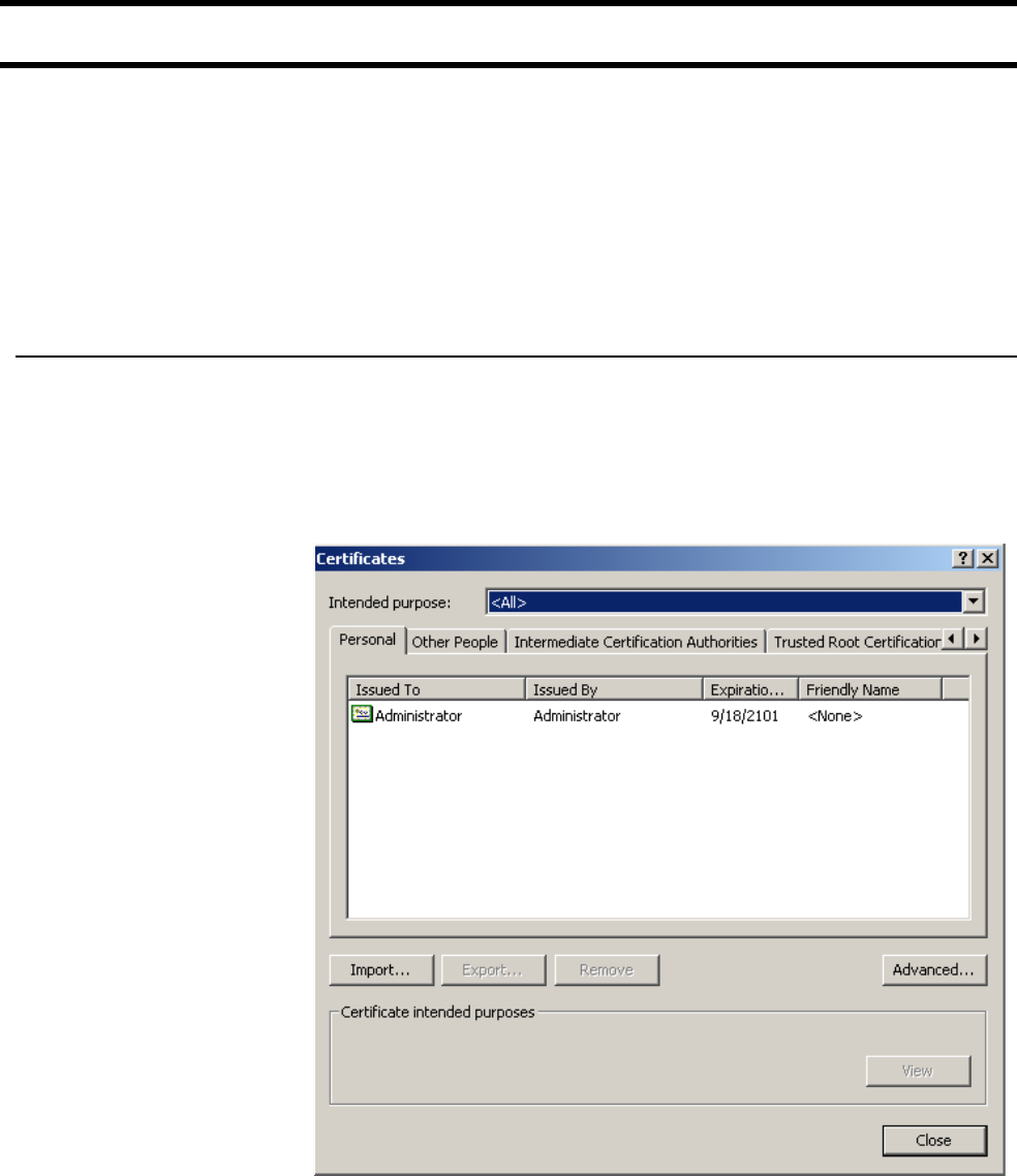
Chapter 14: SSL certificates 154
DRAFT
Installing certificates in a browser
If you are operating as your own certificate authority, installing a certificate signed
by your own CA will still cause a security warning to appear when customers
open the CN3200’s Login page. This occurs because your CA is not part of the
group of well-known certificate authorities included with most browsers. This
means customers will get a security warning when establishing the SSL
connection with the Login page.
To eliminate this warning message, customers must add the public key certificate
for your CA to the list maintained by their browsers.
Internet Explorer To eliminate the certificate warning message in Internet Explorer 6.0, do the
following:
1. On the Tools menu, click Internet Options.
2. Click the Content tab.
3. Click Certificates. The Certificates window opens.
4. Click Import. The Certificate Import Wizard starts. Click Next.
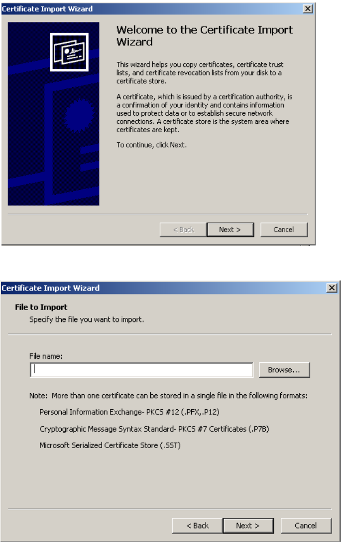
Chapter 14: SSL certificates 155
DRAFT
5. Click Browse.
6. Specify *.pem in the File name box, and press the Enter key, then select
CAcert.pem and click Open.
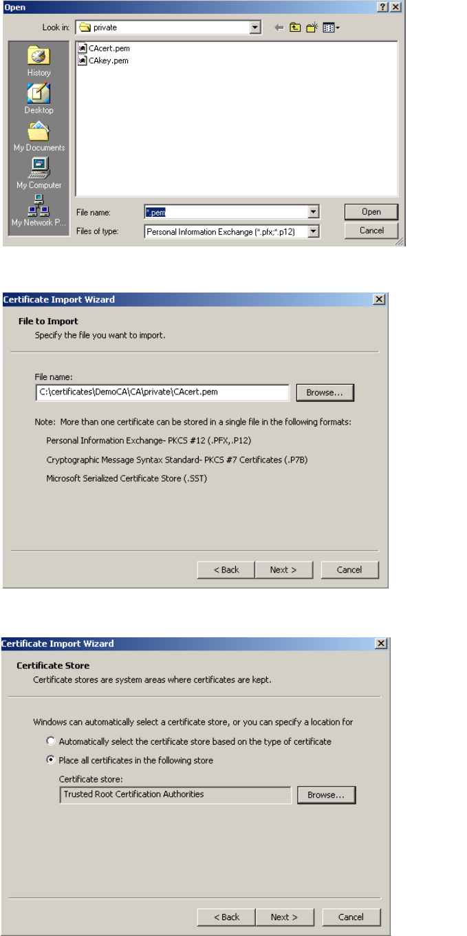
Chapter 14: SSL certificates 156
DRAFT
7. Click Next.
8. Click Next.
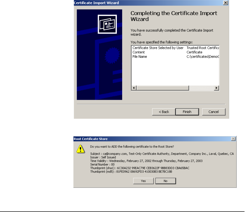
Chapter 14: SSL certificates 157
DRAFT
9. Click Finish.
10. Click Yes.
Customers who do this will no longer see any security warnings.
Netscape
Navigator
To eliminate the certificate warning message in Netscape Navigator 7.1,do the
following:
1. On the Edit menu, click Preferences.
2. Click Privacy & Security.
3. Click Certificates.
4. Click Manage Certificates.
5. Click Authorities.
6. Click Import.
7. Select your Public Key certificate. (If you are using the examples in this
chapter, select C:\certificates\ca\private\CAcert.pem.)
8. Click Open.
9. Select Trust this CA to identify web sites.
10. Optional: Click View to verify the certificate details.
11. Click Ok, Ok.
Chapter 14: SSL certificates 158
DRAFT

Chapter 15: Customizing the public access interface 159
DRAFT
Chapter 15: Customizing the public access interface
Chapter 15
Customizing the public access interface
This chapter provides an overview of the public access interface and
explains how to customize it.

Chapter 15: Customizing the public access interface 160
DRAFT
Overview
The public access interface is the sequence of web pages that customers use to
login, logout, and view the status of their wireless sessions. The CN3200 enables
you to tailor these pages to provide a customized look-and-feel for your site.
Using a RADIUS server, Web pages can be auto-updated, enabling you to
manage multiple units effortlessly.
Common
configuration tasks
The following table lists some common configuration tasks and indicates where
to find more information.
Task For instructions
Changing the Login page and logo. See page 168.
Hosting the login page on your own web server. See page 173.
Displaying custom Welcome or Goodbye pages. See page 171.
Delivering custom content based on a customer’s
location in the network.
See page 171.
Supporting PDAs. See page 172.
Restricting customer logins based on their location
in the network.
See page 181.
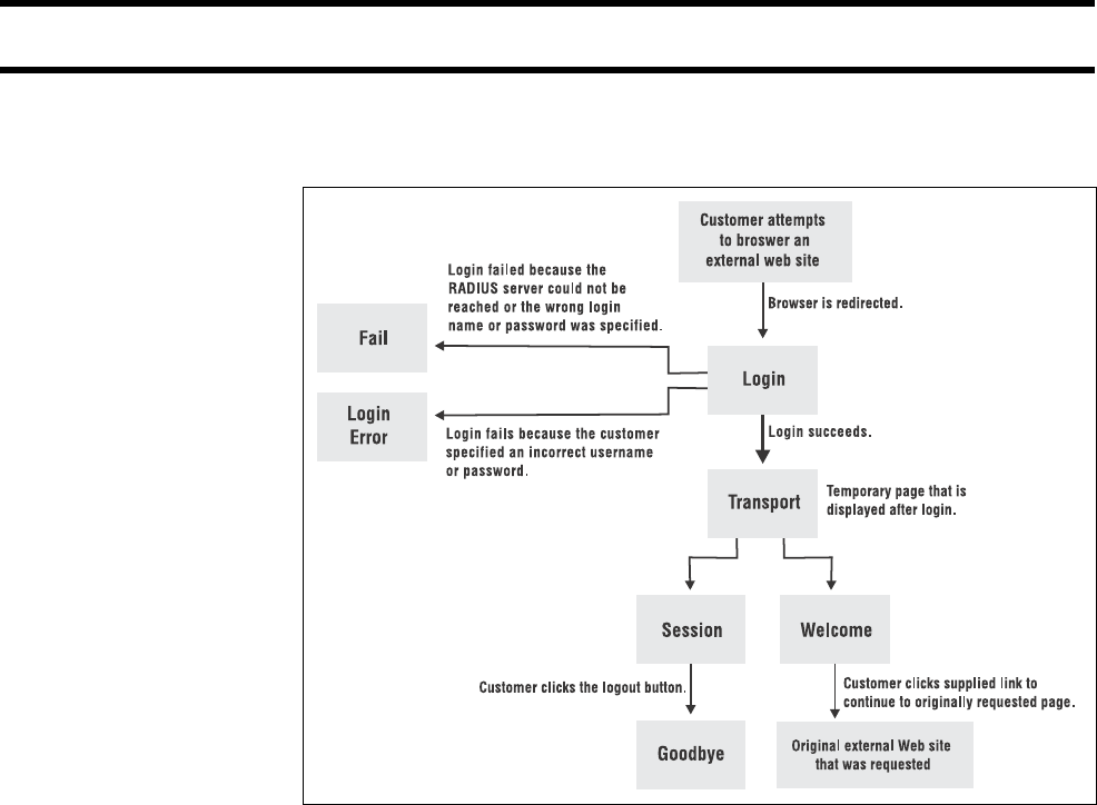
Chapter 15: Customizing the public access interface 161
DRAFT
Site map
The public access interface is composed of seven pages and is structured as
follows:
The pages are split into two groups: internal pages and external pages.
Note: You can also create a remote login page that resides on the web server
and is not downloaded to the CN3200. See “Using a remote login page” on
page 173 for details.
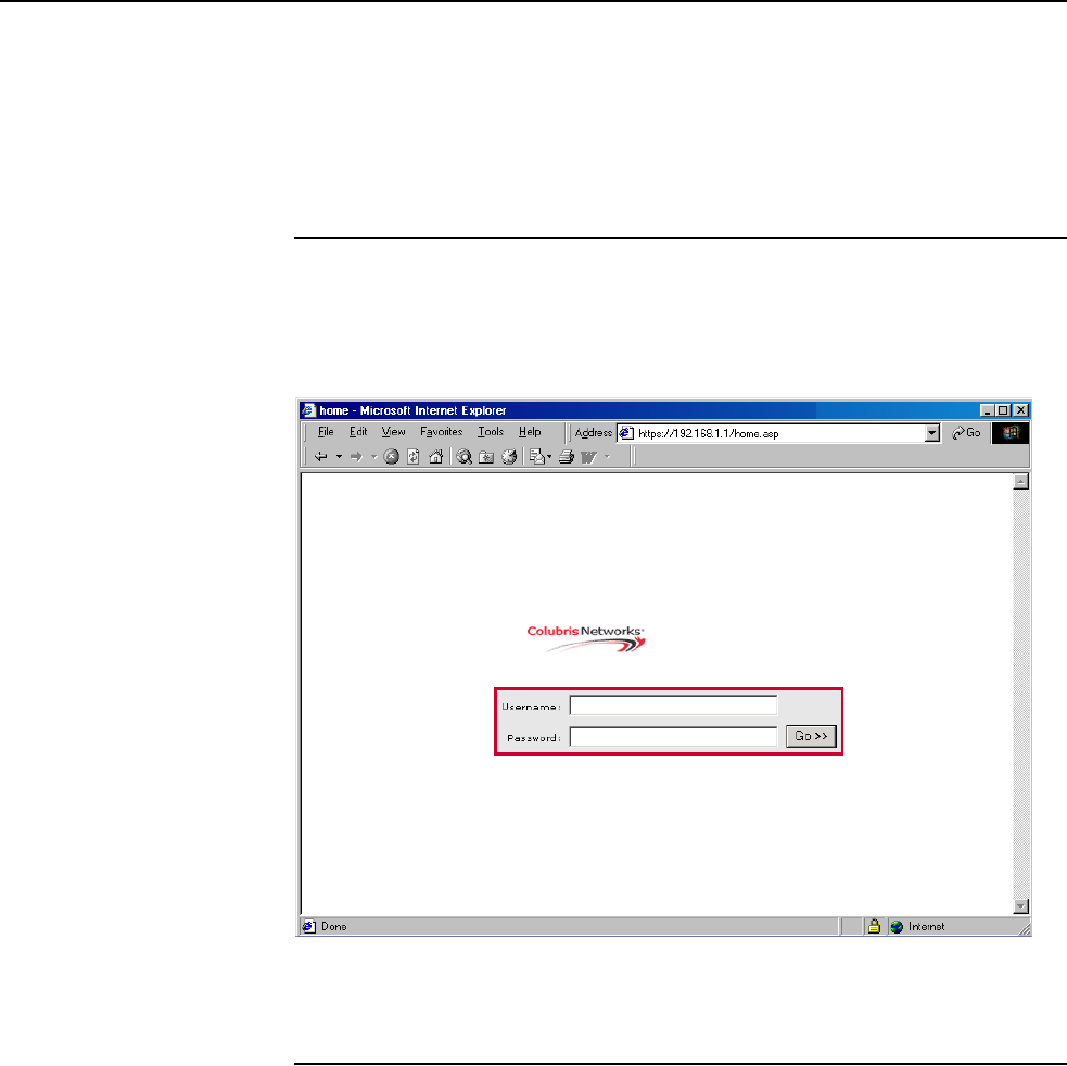
Chapter 15: Customizing the public access interface 162
DRAFT
Internal pages Internal pages are resident on the CN3200. You have the option of using the
default pages supplied with the CN3200 or replacing them with customized
pages of your own design.
To load custom pages you must define their URLs when you create a RADIUS
profile for the CN3200. When the CN3200 authenticates itself to the RADIUS
server it will retrieve the URLs for these pages, then download and activate the
pages.
Login page
This page contains a single graphic element (suitable for a logo or other
identifying element) and two fields: username and password.
The default Login page is:
Note: You can also create a remote login page that resides on an external web
server and is not downloaded to the CN3200. See “Using a remote login page”
on page 173 for details.
Transport page
This page appears briefly and spawns the Session and Welcome pages.
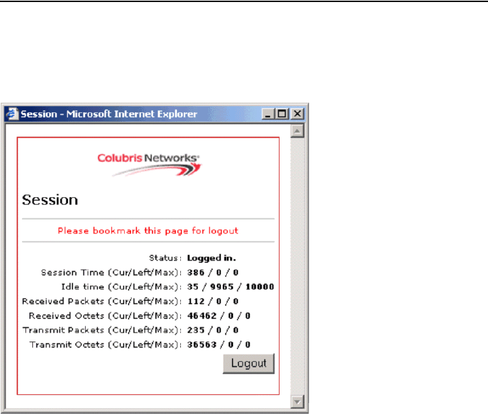
Chapter 15: Customizing the public access interface 163
DRAFT
Session page
This page displays usage statistics for the session, and the logout button the
customer clicks to terminate the session.
The default Session page is:
Managing the session page
The session page is automatically opened after the customer logs in. By default,
it contains the logout button. The following URL can be used to re-open the
session page if a customer accidentally closes it. Without the session page, the
customer will not be able to log out.
http://CN3200_ip:port/session.asp.
For example:
http://192.168.1.1:8080/session.asp
Launching the session page from the Welcome page
You can embed the following URL on the Welcome page, which will dynamically
link to the session page:
http://CN3200_ip:port/session.asp
Forcing a logout
You can force a logout with this URL:
http://CN3200_ip:port/goform/HtmlLogout
For example:
http://192.168.1.1:8080/goform/HtmlLogout
Customers with PDAs
Customers using PDAs that only support a single browser window will never see
the session page. This makes it impossible for them to logout. To solve this
problem, see “Supporting PDAs” on page 172.

Chapter 15: Customizing the public access interface 164
DRAFT
Fail page
This page appears if:
• the CN3200 cannot contact the RADIUS server to authenticate a customer
• the CN3200 fails to be authenticated by the RADIUS server due to bad
username or password on the Security > Authentication page, or wrong
RADIUS configuration on the Security > RADIUS page
External pages External pages are stored on a remote Web server. The CN3200 retrieves the
URLs for these pages in two ways:
• when it authenticates itself to the RADIUS server
• when the CN3200 authenticates a customer using the RADIUS server
By defining unique URLs for each customer, you can provide customized
versions of the external pages.
Note: You can also create a remote login page that resides on an external web
server and is not downloaded to the CN3200. See “Using a remote login page”
on page 173 for details.
Welcome page
The Welcome page includes a link to the page that was originally requested. If
the CN3200 cannot reach the custom URL specified for the Welcome page or if a
custom URL is not defined, it jumps directly to the page originally requested by
the customer.
Goodbye page
This page acknowledges a customer logout.
Login error page
This page appears if the customer cannot be authenticated. The reason is
displayed on the page. You can customize the messages on this page by editing
the file messages.txt. See “Message file” on page 192 for details.

Chapter 15: Customizing the public access interface 165
DRAFT
How it works The following diagram illustrates the sequence of events that occur when a
customer attempts to browse an external web site.

Chapter 15: Customizing the public access interface 166
DRAFT
Customizing the internal pages
This section explains how to customize the four internal pages (Login, Transport,
Session, Fail), as well as the shared image file (logo) and the message file.
Creating new
internal pages
To create new internal pages, use the fully-commented samples provided on the
CD (in the folder \HTML\Colubris) as a starting point For your reference, these
samples are also reproduced at the end of this chapter. (Additional samples are
available at www.colubris.com.)
Important: Do not create new pages by saving an internal page while viewing it
within your web browser. The server-side code is removed when you do this and
the resulting pages will not work. Use the examples on the CD as the base for
your pages.
The internal pages use a number of Colubris-specific ASP functions to display
status information. You can make use of these functions to enhance your custom
pages too. These functions are described starting on page 184.
Important
restrictions
Because the internal pages must be loaded onto the CN3200, the following
restrictions apply to their construction.
• You must specify a URL for all the internal pages, even if you only want to
change one page. The pages you do not change can just be copies of the
standard internal pages.
• Do not alter the ID tags “[!-- Colubris --]” & “[!-- Custom --]” located at the top of
the page.
• Do not alter any JavaScript code, except for the Session window parameters
width and height.
• Only one image can be included on these pages. It must be a .gif file
(recommended size less than 20K). This same image file is shared by all
pages, and must be resident on the CN3200. For instructions on how to
change it, see “Examples” on page 168.
• Do not alter any occurrences of "Get...();" or "GetWelcomeURL();”
• Do not alter any form elements. All names and values should be left intact.
• Do not change the file name extensions of the internal pages.
Loading new
internal pages
To load new internal pages, you must define their URLs using a Colubris-AVPair
value string when you create a RADIUS profile for the CN3200. See Chapter 16
for information on how to create RADIUS profiles.
When the CN3200 authenticates itself, it retrieves the URLs for the custom
pages, then automatically downloads and activates them.

Chapter 15: Customizing the public access interface 167
DRAFT
Colubris-AVPair value string
The following table presents the Colubris-AVPair value strings used for
customizing the internal pages.
Important: The internal pages can only be changed as a group. You cannot,
for example, just use the login-page string in a RADIUS profile. You must use all
required items. This means that the minimum set you can specify in a RADIUS
profile is:
login-page= URL_of_page
transport-page= URL_of_page
session-page= URL_of_page
fail-page= URL_of_page
logo= URL_of_gif_file
Placeholders
The following optional placeholders can be appended to the Colubris-AVPair
value strings for the internal pages.
Internal page Colubris-AVPair value string Notes
Login login-page= URL_of_page Required.
Unless a remote login
page is being used (page
173).
Transport transport-page= URL_of_page Required.
Session session-page= URL_of_page Required.
Fail fail-page= URL_of_page Required.
Re-usable image logo= URL_of_gif_file Required.
This image is shared by
all pages.
Error messages messages= URL_of_text_file Optional.
These messages appear
when various error
conditions occur.
Placeholder Description
%n Returns the NAS ID assigned to the CN3200. By default, this
is the unit’s serial number.
%s Returns the RADIUS login name assigned to the CN3200. By
default, this is the unit’s serial number.
%i Returns the domain name assigned to the CN3200’s Internet
port.
%a Returns the IP address of the CN3200’s interface that is
sending the authentication request.

Chapter 15: Customizing the public access interface 168
DRAFT
Examples These examples show how to accomplish some common customization tasks.
Additional examples are available on the Colubris Networks web site.
Changing the login page and logo
1. Create a folder called newpages on your web sever.
2. Create a file called logo.gif that contains your logo and place it in the
newpages folder.
3. Copy the following files from the \HTML\Colubris\Internal folder on the CD
and place them in the newpages folder.
• login.html
• transport.html
• session.html
• fail.html
4. Edit the login.html to meet the requirements of your site.
5. Add the following entries to the RADIUS profile for the CN3200.
login-page=web_server_URL/newpages/login.html
transport-page=web_server_URL/newpages/transport.html
session-page=web_server_URL/newpages/session.html
fail-page=web_server_URL/newpages/fail.html
logo=web server URL/newpages/logo.gif
Customizing error messages
Several of the internal pages use the functions GetAuthenticationErrorMessage()
and GetSessionStateMessage() to return a string from the file “message.txt.” You
can customize the messages in this file for your installation as follows:
1. Create a folder called newpages on your web sever.
2. Copy the file messages.txt from the \HTML\Colubris\Internal folder on the
CD and place it in the newpages folder.
3. Edit messages.txt with an ASCII editor. Customize the messages to suit your
installation.
4. Add the following entry to the RADIUS profile for the CN3200.
messages=web_server_URL/newpages/messages.txt

Chapter 15: Customizing the public access interface 169
DRAFT
Customizing the external pages
This section explains how to customize the three external pages: Welcome,
Login error, and Goodbye.
Creating new
external pages
In contrast to the internal pages, the external pages do not have any restrictions
on their construction since they reside on a third-party server.
To create new external pages, use the fully-commented samples provided on the
CD (in the folder \HTML) as a starting point. For your reference, these samples
are also included at the end of this chapter.
Activating new
external pages
To activate new external pages, you must define their URLs using the Colubris-
AVPair value string when you create a RADIUS profile for the CN3200 or a
customer. See Chapter 16 for information on how to create RADIUS profiles.
When the CN3200 authenticates itself, or a customer, it retrieves the URLs for
the custom pages, then automatically redirects customers to them when
required.
Note: The CN3200 maintains a separate copy of the URLs for external pages for
each customer. This means it is possible to provide different pages on a per-
customer basis.
Colubris-AVPair value string
The following table presents the Colubris-AVPair value strings used for
customizing the external pages.
Attribute Notes
login-err-url=
URL_of_page [placeholder]
Access to the web server hosting this
page must be granted to all
unauthenticated customers. Do this with
an appropriate access list definition.
(Customers can see this page before
they are logged in.)
welcome-url=
URL_of_page [placeholder]
The customer is authenticated, so the
welcome page can be located on any
URL reachable by the customer.
goodbye-url=
URL_of_page [placeholder]
Access to the web server hosting this
page must be granted to all
unauthenticated customers. Do this with
an appropriate access list definition.
(Customers see this page after they are
logged out.)

Chapter 15: Customizing the public access interface 170
DRAFT
Placeholders
An important feature of the external pages is that they make it easy to deliver a
unique experience for each customer. By appending the following optional
placeholders to the Colubris-AVPair value strings for the external pages, you can
pass important information to the web server. Server-side code can process this
information to generate custom pages on the fly.
Placeholder Description
%c Returns the IP address of the customer’s computer.
%l Returns the URL on the CN3200 where customer login
information should be posted for authentication. This option is
used with the remote login page feature.
%n Returns the NAS ID assigned to the CN3200. By default, this
is the unit’s serial number.
%s Returns the RADIUS login name assigned to the CN3200. By
default, this is the unit’s serial number.
%u Returns the login name of the customer.
%o Returns the original URL requested by the customer.
%i Returns the domain name assigned to the CN3200’s Internet
port.
%p Returns the IP port number on the CN3200 where customer
login information should be posted for authentication.
%a Returns the IP address of the CN3200’s interface that is
sending the authentication request.
%E When the location-aware feature is enabled, returns the
ESSID of the wireless access point the customer is
associated with.
%G When the location-aware feature is enabled, returns the group
name of the wireless access point the customer is associated
with.
%C When the location-aware feature is enabled, returns the
Called-station-id content for the wireless access point the
customer is associated with.
%r Returns the string sent by the RADIUS server when an
authentication request fails. The RADIUS server must be
configured to support this feature. The information contained
in the returned string depends on the configuration of the
RADIUS server.
%m Returns the Calling-station-id content for the wireless access
point the customer is associated with.

Chapter 15: Customizing the public access interface 171
DRAFT
Examples These examples show how to accomplish some common customization tasks.
Displaying custom welcome and goodbye pages
This example shows how to display unique welcome and goodbye pages for
specific customers, or groups of customers.
For this example, assume you have two sets of customers: basic and premium.
To distinguish the two groups, you have setup the customer accounts on the
RADIUS server accordingly. (Perhaps you are using access lists to restrict each
group to a different section of the public network as described on page 220).
1. Create the following two folders on your web sever: basic and premium.
2. Copy the following files from the \HTML\Colubris\External folder on the CD
into both the basic and premium folders on your web server.
• welcome.html
• goodbye.html
3. Edit welcome.html and goodbye.html in each folder and customize them for
each set of customers.
4. Add the following entry to the RADIUS profile for the basic customers.
welcome-url=web_server_URL/basic/welcome.html
goodbye-url=web_server_URL/basic/goodbye.html
5. Add the following entry to the RADIUS profile for the premium customers.
welcome-url=web_server_URL/premium/welcome.html
goodbye-url=web_server_URL/premium/goodbye.html
6. Add the following entry to the RADIUS profile for the CN3200. This gives all
unauthenticated users access to the web server hosting the goodbye page.
access-list=loginserver,ACCEPT,tcp,web server IP address
Delivering dynamically generated content
Another way to generate custom pages is to add placeholders in the URLs for the
custom external pages and then use server-side scripting to dynamically create
the pages. This method provides a powerful mechanism to automatically
generate completely customized pages on a per-user basis. Rather than
designing one or more static pages, as in the previous example, the custom
pages in this example can be built on-the-fly based on customer preferences
stored in a central database, or on a customer’s location within the network.
For example, if you want to generate a custom welcome page for each customer:
1. Add the following entry to the RADIUS profile for the CN3200.
welcome-url=web_server_URL/premium/welcome.html
?loginname=%u&IPaddress=%i
2. Create a server-side script to retrieve the login name (%u) and the CN3200’s
IP address (or domain name). The script can use this information to then
display a custom page based on customer’s preferences (stored in the
server’s database) and location within the wireless network.

Chapter 15: Customizing the public access interface 172
DRAFT
Supporting PDAs
Customers using PDAs that only support a single browser window will have
difficulty using the public access interface in its standard configuration.
The problem
Once a customer logs in to the public access interface, two web pages are sent
to their browser: the Welcome page and the Session page.
The Session page contains a logout button. Customers who are unable to view
this page will not be able to log out.
The solution
To solve the problem, modify the Welcome page to include a logout button. You
can do this as follows:
1. Create a folder called PDAcustomers on your web sever.
2. Copy welcome.html from the \HTML\Colubris\External folder on the CD
into this folder.
3. Edit welcome.html to include a logout link with the target:
http://CN3200_ip:port/goform/HtmlLogout.
For example:
http://192.168.1.1:8080/goform/HtmlLogout.
Add a warning to this page that tells PDA customers to bookmark the
Welcome page so that they can logout.
4. Add the following entry to the RADIUS profile for all PDA customers.
welcome-url=web_server_URL/PDAcustomers/welcome.html
Chapter 15: Customizing the public access interface 173
DRAFT
Using a remote login page
The CN3200 provides an option that allows you to redirect customers to a remote
server to log in to the public access interface instead of using the internal login
page.
Advantages Hosting the login page on a remote server provides you with the following
benefits:
• The login page is completely customizable. You are not bound by the limits
imposed by loading a login page onto the CN3200.
• Customers can login to the public access interface without exposing their web
browsers to the SSL certificate on the CN3200. This eliminates warning
messages caused by having an SSL certificate on the CN3200 that is not
signed by a well-known certificate authority. Only applies when using the NOC
authentication feature.
• If you want to support secure login with SSL, but have multiple CN3200s, using
a remote login page means you only need to purchase a single SSL certificate
signed by a well-known certificate authority, instead of one for each access
point.Only applies when using the NOC authentication feature.
Activating a remote
login page
The remote login page is activated by adding Colubris-AVPair value strings to the
RADIUS profile for the CN3200. See Chapter 16 for a detailed discussion on how
to use these strings.
Colubris-AVPair value string
The following table summarizes the Colubris-AVPair value strings for the remote
login page.
Item Colubris-AVPair value string
External login login-url= URL_of_the_page [placeholder]
Access to the web server hosting this page must be
granted to all unauthenticated customers. Do this with an
appropriate access list definition.
NOC certificate ssl-noc-certificate= URL_of_the_Certificate
Certificate issued to the application on the web server that
will send customer info to the CN3200 for authentication.
For NOC-based authentication only.
NOC CA certificate ssl-noc-ca-certificate= URL_of_the_certificate
Certificate of the certificate authority (CA) that issued the
NOC certificate.
For NOC-based authentication only.

Chapter 15: Customizing the public access interface 174
DRAFT
Placeholders
The following placeholders can be added to the login-url string.
Important: To use the remote login page, you must provide a complete set
of internal pages (except for login.html), which includes:
transport-page= URL_of_page
session-page= URL_of_page
fail-page= URL_of_page
logo= URL_of_gif_file
How it works Although the remote login page feature enables you to host the public access
login page on a remote web server, authentication of customers is still performed
by the CN3200 via a RADIUS server. To accomplish this, the remote web server
must send customer login information back to the CN3200. There are two ways
to accomplish this: basic remote login or using the NOC-based authentication
feature.
Placeholder Description
%c Returns the IP address of the customer’s computer.
%l Returns the URL on the CN3200 where customer login
information should be posted for authentication.
%n Returns the NAS ID assigned to the CN3200. By default, this
is the unit’s serial number.
%s Returns the RADIUS login name assigned to the CN3200. By
default, this is the unit’s serial number.
%o Returns the original URL requested by the customer.
%i Returns the domain name assigned to the CN3200’s Internet
port.
%p Returns the port number on the CN3200 where customer
login information should be posted to for authentication.
%a Returns the IP address of the CN3200’s interface that is
sending the authentication request.
%E When the location-aware feature is enabled, returns the
ESSID of the wireless access point the customer is
associated with.
%G When the location-aware feature is enabled, returns the group
name of the wireless access point the customer is associated
with.
%C When the location-aware feature is enabled, returns the
Called-station-id content for the wireless access point the
customer is associated with.
%r Returns the string sent by the RADIUS server when an
authentication request fails. The RADIUS server must be
configured to support this feature. The information contained
in the returned string depends on the configuration of the
RADIUS server.
%m Returns the Calling-station-id content for the wireless access
point the customer is associated with.

Chapter 15: Customizing the public access interface 175
DRAFT
Basic remote login
The following diagram shows the sequence of events for a typical customer
session when using basic remote login.
Security issues
• It is recommended that the web server hosting the remote login page be
secured with SSL (requires an SSL certificate from a well-know CA), to ensure
that customer logins are secure. Without SSL security, logins are exposed and
may be compromised, enabling fraudulent use of the network.
• Communications between the customer’s browser and the CN3200 is always
SSL-based. The default certificate on the CN3200 will generate a warning on
the customer’s browser unless replaced with a certificate signed by a well-
known CA.

Chapter 15: Customizing the public access interface 176
DRAFT
Example
To enable a basic remote login page, do the following:
1. Create the following folder on your web sever: newlogin
2. Copy the following files from the \HTML\Colubris\Internal folder on the CD
and place them in the newlogin folder.
• login.html
• transport.html
• session.html
• fail.html
•logo.gif
3. Add the following entries to the RADIUS profile for the CN3200.
login-url=web_server_URL/newlogin/login.html?loginurl=%l
transport-page=web_server_URL/newlogin/transport.html
session-page=web_server_URL/newlogin/session.html
fail-page=web_server_URL/newlogin/fail.html
logo=web server URL/newlogin/logo.gif
access-list=loginserver,ACCEPT,tcp,web_server_IP_address
use-access-list=loginserver
4. Customize login.html to accept username and password information from
customers and then send it to the CN3200. You can use code similar to the
following example to redirect the customer’s web browser to the login URL on
the CN3200 for authentication:
<form action="https://CN3200.wireless.colubris.com:8090/goform/
HtmlLoginRequest" method="POST">
For more flexibility, the remote login page should be written using a server-
side scripting language such as ASP, PHP, or PERL. This enables the remote
login page to take advantage of the placeholders that may have been defined
in the login-url section of the RADIUS profile. See section “Placeholders” on
page 174 for more information about the placeholders.
NOC-based authentication
The NOC authentication feature provides a secure way of authenticating public
access customers, with strong mutual authentication between the web server
hosting the remote login page and the CN3200 used for authenticating customer
logins. This occurs via the two Colubris-AVPair value strings (ssl-noc-certificate
and ssl-noc-ca-certificate), which define the locations of two certificates. These
certificates enable the CN3200 to validate that the customer information it
receives does indeed come from a trusted application. For example, from a login
application on the web server.
Additional security is provided via the NOC access list. You use this list to define
the set of remote IP addresses that the CN3200 will accept authentication
requests from. If a request is received from an address not in this list, it is
discarded.
Since this method does not expose a customer’s browser to the CN3200, there is
no need to install a certificate signed by a well-known certificate authority on the
CN3200. (You can however, install a certificate on the CN3200 if you want to
secure communications between it and the web server hosting the remote login
page.)

Chapter 15: Customizing the public access interface 177
DRAFT
The following diagram shows the sequence of events for a typical customer
session when using the NOC-based authentication feature.
Security issues
• HTTPS can be used on the web server to secure the login page. To avoid
warning messages on the customer’s browser, the SSL certificate installed on
the web server should be signed by a well-known CA.
• When establishing the SSL session with the CN3200, the login application
must supply its SSL certificate. In a standard SSL setup, the CN3200 would
just use the CA for this certificate to validate its identity. However, the CN3200
does not want to accept SSL connections from any remote entity with a valid
certificate. Rather, it only wants to accept connections from a specific entity:
the remote login application. Therefore, to uniquely identify itself, the login
application must supply the same certificate configured in the CN3200’s
RADIUS account as ssl-noc-certificate. The CN3200 verifies that this
certificate has been signed by the certificate authority whose public key
certificate is pointed to by ssl-noc-ca-certificate.
• To identify itself, the CN3200 uses the SSL certificate configured on the
Security > Certificates page. For added security, the login application could
also check that this SSL certificate has been signed by the certificate authority
for which the web server has the public key certificate. (By default, this
certificate is not signed by a well-known CA.)
• An effective way to handle the certificates would be to:
Communications between the login application and the CN3200
• Once a customer has supplied login information on the remote login page, the
login application must submit an authenticaiton request containing the
customer’s login name, password, and IP address to the CN3200 by
establishing an SSL session to the following URL:
https://CN3200_ip:8090/goform/HtmlNocLoginRequest
?username=username&password=password&ipaddr=customer_ip
CN3000_ip is the IP address of the CN3200 or you could use a domain name if
you have defined one using the hosts file on the web server. (By default, the
secure web server on the CN3200 operates on port 8090. This can be
changed on the Management Tool page if required.)
Install an SSL certificate signed by a well-known CA on the web server hosting
the remote login page. This certificate will be used to secure customer logins.
Install a second SSL certificate on the web server hosting the remote login
page. This certificate will be used by the login application to secure
communications with the CN3200. This certificate could be signed by your
own CA to reduce cost.
Install an SSL certificate on the CN3200 (optional). This certificate could also
be signed by your own CA to reduce cost. Use the Security > Certificates
page to install it. This certificate will be used to secure communications
between the CN3200 and the login application on the web server.
If the SSL certificate installed on the CN3200 is signed by an intermediate
certificate authority, the PKCS#12 file imported into the CN3200 must contain:
• the private key for the CN3200’s SSL certificate
• the whole set of X.509 certificates required by an SSL client to create the
certificate chain to validate the CN3200’s SSL certificate: Root CA cer -->
Intermediate CA (1) cert --> ...--->Intermediate CA(n) --> CN3xxx cert.
This enables the SSL client to be aware of the entire certificate chain, even if
by default it only knows about the root CA for this certificate chain.
Chapter 15: Customizing the public access interface 178
DRAFT
The CN3200 requires that the contents of the Host HTTP header match the
actual domain name/IP address and port the CN3200 is operating on:
Host: CN3200_domain_name:secure_web_server_port_number
or
Host: CN3200_IP_address:secure_web_server_port_number
This will usually be the case, unless the CN3200 is behind a device that
provides network address translation (NAT). In this situation, the login
application must manually forge the Host HTTP header. The easist way to do
this is to define login-url with the %i and %p placeholders. This returns the
domain name of the CN3200 and the port number of its secure web server.
The login application can then contstruct the appropriate Host HTTP header.
Example 1
Assume that the CN3200 is not behind a NATing device, and that its IP address
is 192.168.4.2. The subject DN in its SSL certificates is www.noc-cn3000.com.
The Host HTTP header should be set to one of:
• Host: www.noc-cn3000.com:8090
• Host: 192.168.4.2:8090
Example 2
Assume that the CN3200 is behind a NATting device. The device has the
address 192.168.30.173, and the CN3200 has the address 192.168.4.2. A
NAT mapping is defined on the NATting device that redirects traffic recieved on
port 8090 to 192.168.4.2:8090.
The login application must send its requests to 192.168.30.173, which results
in a HTTP Host header that contains one of the following:
• Host: natting.router.com:8090
• Host: 192.168.30.173:8090
When this request is forwarded to the CN3200, it will be rejected. To solve the
problem, the login appication must forge the host HTTP header. This is easily
done by plugging in the values returned by the %i, %a, and %p placeholders.
For example:
Host: %i:%p
or
Host: %a,%p
• The CN3200 sends the username and password to the RADIUS server to
authenticate the customer. If authentication is successful, the customer’s IP
address is used to grant wireless network access to the customer’s computer.
• The CN3200 returns a positive or negative answer for the customer login,
along with the relevant URLs that may be needed by the login application in
order to redirect the customer to either a Welcome page or a Login error page
located on the web server. This information is returned as standard HTML. The
login application must parse this information to retrieve the response. All
possible responses are described in “Authentication results” on page 348.
Example
This is a simple example showing how to use the NOC authentication feature.
See Chapter 20 for an example of the code that would be needed by a login
application to communicate with the CN3200.
1. Create the following folder on your web sever: newlogin
2. Copy the following files from the \HTML\Colubris\Internal folder on the CD
and place them in the newlogin folder.
Chapter 15: Customizing the public access interface 179
DRAFT
• login.html
• transport.html
• session.html
• fail.html
•logo.gif
3. Customize login.html to accept username and password information from
customers and then send it to the CN3200. You could use code similar to the
following PHP example to send login information back to the CN3200 for
authentication:
https://ipaddress of CNx;8090/goform/HtmlNocLoginRequest
?username=username&password=password&ipaddress=customer_
ip
The variable loginurl contains the URL on the CN3200 where customer
information is sent for authentication.
4. Start the management tool.
5. On the main menu, click Security, then click Authentication.
Chapter 15: Customizing the public access interface 180
DRAFT
6. Click the Advanced Settings button.
7. Enable the NOC authentication feature.
8. Add the IP address of the web server to the Allowed Addresses box.
9. Click Save.
10. In the RADIUS profile for the CN3200, define the following:
login-url= URL_of_page_on_remote_server
access-list=loginserver,ACCEPT,tcp,web_server_IP_address,443
ssl-noc-certificate= URL_of_the_certificate
ssl-noc-ca-certificate= URL_of_the_certificate
transport-page=web_server_URL/newlogin/transport.html
session-page=web_server_URL/newlogin/session.html
fail-page=web_server_URL/newlogin/fail.html
logo=web server URL/newlogin/logo.gif
use-access-list=loginserver
Forcing customer logout
Customers can be logged out by calling the following URL:
https://CN3200_ip:8090/goform/HtmlNocLogoutRequest
?ipaddress=customer_ip
Important: This request must come from the login application (or another other
application that is using the same SSL certificate).
The CN3200 returns a positive or negative answer for the customer logout as
standard HTML. The login application must parse this information to retrieve the
response.
Logout success
<HTML>
NOC_INFO_STATUS=NOC_STATUS_SUCCESS
</HTML>
Logout failure
<HTML>
NOC_INFO_STATUS=NOC_STATUS_FAILURE
NOC_INFO_INT_ERR_MESSAGE=<error message>
</HTML>
Note: These definitions are contained in noc.h which is described on page 348.

Chapter 15: Customizing the public access interface 181
DRAFT
Location-aware authentication
This feature enables you to control logins to the public access network based on
the wireless access point a customer is connected to.
Important: This feature does not support 802.1x customers and devices using
MAC-based authentication.
How it works When a customer attempts to login to the public access network, the CN3200
sets the Called-Station-ID in the RADIUS access request to one of the following
values (your choice):
• the MAC address of the wireless port the customer is associated with
• the ESSID of the access point the customer is associated with
• a group name (you can assign a group name to each wireless access point)
Consider the following topology for a fictional small hotel. The restaurant and
lounge are available to all hotel customers who subscribe to the wireless service.
However, the conference room is available only to a specific group of guests who
book it in advance.
In this example, the access points in each area are assigned the following unique
group names:
• conference_room
• restaurant
• lounge
When a customer logs in, server-side code can be used to determine the access
point they are associated with by inspecting the Called-Station-ID. Then, using
their account information, access can either be granted or denied.
Security o maintain the security of the network logins, the CN3200 will only accept
location-aware information from a CN300 that has a matching shared secret to
its own.
Roaming If your network supports roaming, each time a customer switches wireless
access points the CN3200 will send the following:
• Called-Station-ID = MAC address or ESSID or Group name.
• Service-Type = 8744 (decimal)
This information enables you to track the movements of your customers. If they
roam to an unauthorized access point, you can log them out.
In the fictional small hotel, if a customer roams from the lounge to the conrerence
room, server-side code can evaluate the Called-Station-ID to determine if the
customer has access. If not, the customer can be logged out.
Configuration To activate location-aware authentication, do the following:
1. Open the Security > Authentication > Advanced Settings page,
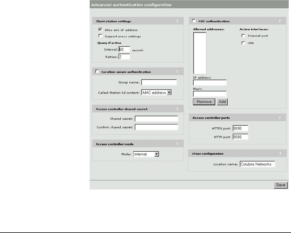
Chapter 15: Customizing the public access interface 182
DRAFT
2. Enable the Location-aware authetication option. Configure the parameters
as described in the section that follows.
Parameters Group name
Specify a group name for the access point. This name is used to identify
customer logins via the Called-Station-ID. You can assign the same group name
to more than one access point.
Called-Station-ID content
Choose the value that you want the CN3200 to return in the Called-Station-ID
when it generates a RADIUS access request for a customer login.
• the MAC address of the wireless port the customer is associated with
• the SSID of the access point the customer is associated with
• the group name of the access point the customer is associated with

Chapter 15: Customizing the public access interface 183
DRAFT
iPass support
The CN3200 provides support for the Generic Interface Specification from iPass
which enables you to create an iPass-compatible hotspot.
To setup the CN3200 as an iPass hotspot, you must define the IPass
authentication server on the Security > RADIUS page. You can use either Profile
1 or Profile 2 to do this.

Chapter 15: Customizing the public access interface 184
DRAFT
ASP functions
The following ASP functions can be called from the internal pages only.
Errors GetAuthenticationErrorMessage()
Returns a message (from message.txt) indicating the status of the last
authentication request. This function is used on the default Login and Fail pages
to update the customer on the status of the login or logout.
RADIUS GetMsChapV2Failed()
Returns the MS CHAP V2 error string. This function is only supported if you
select MSCHAP V2 as the authentication scheme on the CN3200 (Security >
RADIUS page). The RADIUS server must also support this feature. For a list of
possible return values see RFC 2759.
GetRadiusNasId()
Returns the NAS ID configured for RADIUS Profile on the CN3200. (See “Setting
up the CN3200 RADIUS client” on page 95 for details on setting the NAS ID.)
This can be used to identify the CN3200 that authenticated a customer. For an
example of how this function is used, see GetNasAddress().
GetRadiusReplyMessage()
Returns the string sent by the RADIUS server when an authentication request
fails. The RADIUS server must be configured to support this feature. The
information contained in the returned string depends on the configuration of the
RADIUS server.
GetNasAddress()
Returns the fully-qualified domain name of the CN3200 as is specified in the
currently loaded SSL certificate.
Example
In certain instances you may want customers to register for an account before
they log in. To accomplish this you could modify the Login page by adding a
register button. This would redirect the customer’s browser to a registration web
server where they would setup their account. (This page must be made
accessible to non-authenticated customers using the appropriate access list
rule.)
To avoid having the customer login once registration is complete, the registration
web server can send the customer back to the CN3200 using a special URL that
will automatically log the customer into the public access interface.
Assuming the registration server is 192.169.30.1, the register button code on the
Login page might look something like this:
<FORM><INPUT
onclick="javascript:window.location='https://192.168.30.1/demo-
php/register.php?
NASip=<%GetNasAddress();%>&NASid=<%GetRadiusNasId();%>';"
type=button value="Click Here to Register">
</FORM>

Chapter 15: Customizing the public access interface 185
DRAFT
The NAS ID and NAS address are required when the customer is redirected back
to the CN3200 after registration. The code on the registration web page would
look something like this:
// Registering user information in the backend database
RegisterUser($username,
$firstname,
$lastname,
$company,
$title,
$phone,
$email,
$NASid, // identifies the CN3200 the customer is connected to
$NASip
);
// set URL to redirect browser to
$targetURL = "location: https://
" . $NASip . ":8090/goform/HtmlLoginRequest?
username=" . $username . "&password=" . $password;
// When done
header($targetURL);
The target URL is built using the NAS IP and username and password. The form
name is hard-coded.
Page URLs GetSessionUrl()
Returns the URL of the Session page.
GetWelcomeUrl()
Returns the URL of the Welcome page.
GetFailRetryUrl()
Returns the URL of the next internal page to display as follows:
• Returns the Fail page URL if a login or logout request is currently pending.
• Returns the Transport page URL if the customer is already logged in.
This function is designed to be used in conjunction with IsRequestPending().
GetOriginalUrl()
Returns the URL the customer tried to access before being redirected to the
Login page.
Session status and
properties
IsRequestPending()
Returns ‘yes’ if a login or logout request is already pending for the current
customer. This function is useful when a RADIUS server is slow to respond and a
customer repeatedly clicks the login or logout buttons. For example, consider the
following code which could be used to modify the Fail page to address this
problem.
function loading() //called when the fail page is first loaded
if ("<% IsLoggedIn(); %>" == "yes") //logout is pending, so refresh page
refresh();
else
{
// customer is already logged out or a login is currently pending
// (i.e., customer clicked login button twice
if ("<% IsRequestPending(); %>" == "yes")

Chapter 15: Customizing the public access interface 186
DRAFT
setTimeout('refresh()',3000);
else //no login or logout is pending and customer is logged out
document.form1.close.value = "Close window"; //change button label
}
}
function refresh() // refresh the Fail page
{document.location="<%GetFailRetryUrl();%>"; }
IsLoggedIn()
Returns "yes" if the customer is logged in. See IsRequestPending() for an
example that shows how to use this function.
GetSessionStateMessage()
Returns a message (from message.txt) indicating the status of the customer
session.
GetUserName()
Returns the username for the current customer.
GetMaxSessionTime()
Returns the total amount of connection time configured for the current customer
session in minutes and seconds in the format: mm:ss.
GetMaxSessionTimeHMS()
Returns the total amount of connection time configured for the current customer
session in hours, minutes and seconds in the format: hh:mm:ss.
ConvertMaxSessionTime(unit)
Returns the total amount of connection time configured for the current customer
in the specified unit.
For example if the customer account is configured for 5000 seconds, then:
• ConvertSessionTime("y") returns 0, calculated as (5000 / (365*24 *60*60)).
• ConvertSessionTime("d") returns 0, calculated as (5000 / (24*60*60)).
• ConvertSessionTime("h") returns 1, calculated as (5000 / (60*60)).
• ConvertSessionTime("m") returns 83, calculated as (5000 / 60).
• ConvertSessionTime("s") returns 5000, calculated as (5000 / 1).
yYears
dDays
hHours
m Minutes
s Seconds

Chapter 15: Customizing the public access interface 187
DRAFT
TruncateMaxSessionTime(unit)
Returns the total amount of connection time configured for the current customer
truncated to the specified unit.
For example if the customer account is configured for 5000 seconds, then:
• TruncateSessionTime("y") returns 0.
• TruncateSessionTime("d") returns 0.
• TruncateSessionTime("h") returns 1.
• TruncateSessionTime("m") returns 23.
• TruncateSessionTime("s") returns 20.
GetSessionRemainingIdleTime()
Returns the amount of time remaining until the customer will be logged out due to
inactivity.
GetSessionTime()
Returns session duration for the current customer in minutes and seconds in the
format: mm:ss.
GetSessionTimeHMS()
Returns session duration for the current customer in hours, minutes and seconds
in the format: hh:mm:ss.
ConvertSessionTime(unit)
Returns session duration for the current customer in the specified unit. See
ConvertMaxSession time for details.
TruncateSessionTime(unit)
Returns session duration for the current customer truncated to the specified unit.
See TruncateMaxSession time for details.
SetSessionRefreshInterval(sec)
Specifies the refresh interval for the Session page in seconds.
GetSessionRemainingTime()
Returns the amount of connection time remaining for the current customer
session in minutes and seconds in the format: mm:ss.
yYears
dDays
hHours
m Minutes
s Seconds

Chapter 15: Customizing the public access interface 188
DRAFT
GetSessionRemainingTimeHMS()
Returns the amount of connection time remaining for the current customer
session in hours, minutes and seconds in the format: hh:mm:ss.
ConvertSessionRemainingTime(unit)
Returns the total amount of connection time remaining for the current customer
in the specified unit. See ConvertMaxSession time for details.
TruncateSessionRemainingTime(unit)
Returns the total amount of connection time remaining for the current customer
truncated to the specified unit. See TruncateMaxSession time for details.
GetMaxSessionIdleTime()
Returns the total amount of idle time configured for the current customer session.
GetSessionIdleTime()
Returns the amount of time the current session has been idle.
GetSessionInputPackets()
Returns the number of packets received by the current customer session.
GetSessionInputOctets(div)
Returns the number of octets received by the current customer session.
If you specify a value for the optional parameter div, then the return value is the
number of octets divided by div.
GetSessionOutputPackets()
Returns the number of packets sent by the current customer session.
GetSessionOutputOctets(div)
Returns the number of octets sent by the current customer session.
If you specify a value for the optional parameter div, then the return value is the
number of octets divided by div.
Session quotas These functions let you retrieve the quota limits that are set for the current
customer session. If any of these limits are reached, the customer is logged out.
For details see “Quotas” on page 229.
GetSessionRemainingInputPackets()
Returns the number of incoming packets the current customer session can still
receive. This value is a decimal string (10 characters) representing a 32-bit
unsigned integer.

Chapter 15: Customizing the public access interface 189
DRAFT
GetSessionRemainingInputOctets(div)
Returns the number of incoming octets the current customer session can still
receive. This value is a decimal string (20 characters) representing a 64-bit
unsigned integer.
If you specify a value for the optional parameter div, then the return value is the
number of octets divided by div.
GetSessionRemainingOutputPackets()
Returns the maximum number of outgoing packets the current customer session
can still send. This value is a decimal (10 characters) string representing a 32-bit
unsigned integer.
GetSessionRemainingOutputOctets(div)
Returns the maximum number of outgoing octets the current customer session
can still send. This value is a decimal string (20 characters) representing a 64-bit
unsigned integer.
If you specify a value for the optional parameter div, then the return value is the
number of octets divided by div.
GetMaxSessionInputPackets()
Returns the maximum number of incoming packets the current customer session
can receive. This value is a decimal string (10 characters) representing a 32-bit
unsigned integer.
GetMaxSessionInputOctets(div)
Returns the maximum number of incoming octets the current customer session
can receive. This value is a decimal string (20 characters) representing a 64-bit
unsigned integer.
If you specify a value for the optional parameter div, then the return value is the
number of octets divided by div.
GetMaxSessionOutputPackets()
Returns the maximum number of outgoing packets the current customer session
can send. This value is a decimal string (10 characters) representing a 32-bit
unsigned integer.
GetMaxSessionOutputOctets(div)
Returns the maximum number of outgoing octets the current customer session
can send. This value is a decimal (20 characters) string representing a 64-bit
unsigned integer.
If you specify a value for the optional parameter div, then the return value is the
number of octets divided by div.

Chapter 15: Customizing the public access interface 190
DRAFT
iPass support iPassGetLoginUrl()
Returns the iPass Login URL.
iPassGetAbortLoginUrl()
Returns the iPass Abort Login URL.
iPassGetLogoffUrl()
Returns the iPass Logout URL.
iPassGetRedirectResponseCode()
Checks if the iPass authentication server is reachable and enabled. Returns one
of the following values:
iPassGetAccessProcedure()
Returns the access procedure supported by the CN3200. The CN3200 supports
procedure version 1.0.
iPassGetLocationName()
Returns the location name defined on the Security > Authentication page. By
default this is set to Colubris Networks.
iPassGetAccessLocation()
Returns a value which can be used to determine the access point a customer is
connected to. This is useful when you are using one or more CN300s in addition
to the CN3200.
• If a customer logs into the CN300, this function returns the MAC address of the
CN300’s downsteam port.
• If a customer logs into the CN3200, this function returns the MAC address of
the CN3200’s LAN port.
iPassGetLoginResponseCode()
Returns one of the following values when a customer attempts to login to iPass:
0 Authentication server is reachable and enabled..
105 The authentication server could not be reached or is unavailable.
255 The authenticaiton server could not be reached due to an error on the
CN3200 (Internet port not up, for example).
50 Login was successful.
100 Login failed. Access was rejected.
102 Login failed. Authentication server error or timeout.
201 Authentication is pending.
255 The authenticaiton server could not be reached due to an error on the
CN3200 (Internet port not up, for example).

Chapter 15: Customizing the public access interface 191
DRAFT
iPassGetLoginResponseCode()
Returns one of the following values when a customer attempts to logout from
iPass:
150 Logout was successful.
255 The authenticaiton server could not be reached due to an error on the
CN3200 (Internet port not up, for example).

Chapter 15: Customizing the public access interface 192
DRAFT
Message file
The functions GetAuthenticationErrorMessage() and GetSessionStateMessage()
are used in various internal pages to return a string from the file “message.txt”.
You can customize the messages in this file for your installation. See
“Customizing the internal pages” on page 166 for instructions on loading a
custom message file.
The default message file contains the following messages:
# CN3xxx Message file
# The messages in this file are returned by the following two functions:
# - GetSessionStateMessage();
# - GetAuthenticationErrorMessage();
#
# To customize these messages, edit the text between quotes only.
# Messages returned by GetAuthenticationErrorMessage();
# The customer logged out, but no URL for the Goodbye page was defined..
err-msg-logout-no-goodbye-url = "You have been logged out."
# The customer login was rejected by the server, but the no URL for the
# Login Error page was defined. The rejection may be due to any
# number of factors and depends on how access is granted by the server.
# Possible causes include: invalid username or password, no more connection
# time available, account expired.
err-msg-login-refused = "Your login was refused."
# The CN3xxx encountered an abnormal condition.
# This error message should not appear in the course of normal operations.
err-msg-internal-error = "Network access error. Code = "
# The maximum number of customers are already connected to the CN3xxx.
err-msg-max-user-reached = "No connection is currently available. Please try again later."
# The customer is already logged in.
err-msg-already-logged-in = "The username you specified is already logged in."
# The customer's password is longer that the limit of 127 characters.
err-msg-password-too-long = "The password you specified is too long."
# The customer's username is longer than the limit of 127 characters
err-msg-username-too-long = "The username you specified is too long."
# This only occurs during the short periods when the CN3xxx is in the process
# of authenticating itself to the RADIUS server.
err-msg-service-initializing = "The service is initializing, please try again later."
# The customer did not provide a username.
err-msg-missing-username = "You did not provide a username."
# The CN3xxx could not authenticate the customer because no reply was received from the RADIUS
server.
# The network may be down or the server itself may be down.
err-msg-login-timeout = "You cannot be logged in at this time. Please try again later."
# The CN3xxx could not authenticate the customer because there is no RADIUS server spcified in
the
# the configuration. In the management, go to the Security > Radius page and enter the address
of your RADIUS Server.
err-msg-missing-aaa-servers= "Incomplete configuration: You must configure at least one RADIUS
Server."
# This only occurs when the CN3xxx is not able to reach the RADIUS servers anymore to
authenticate the customers.
err-msg-lost-service = "The Service is down, please try again later."
# Messages returned by GetSessionStateMessage();
# The customer is logged in. (MAC address has been verified.)
stat-logged-in = "Logged in."
# The customer's computer is not replying to ARP request or has changed its MAC address.
stat-lost-carrier = "Logged out. Computer was unreachable."
# The customer's session has been idle for too long
stat-idle-timeout = "Logged out. (Idle timeout.)"

Chapter 15: Customizing the public access interface 193
DRAFT
# The customer has exhausted the available session time.
stat-session-timeout = "Logged out. (Reached the session time limit.)"
# User was logged out due to administrator termination
stat-admin-reset = "Logged out. (Administrator terminated the session.)"
# The network authentication software is down.
stat-nas-is-rebooting = "The network service is currently unavailable."
# The customer has already logged out.
stat-logged-out = "Already logged out."
# Pending login in request
stat-logging-in = "Your login request is pending. Please wait."
# Pending login out request
stat-logging-out = "Your logout request is pending. Please wait."
# The customer's session exceeded its quotas
stat-quota-exceeded= "Logged out. (Quota Exceeded.)"