Hewlett Packard Enterprise AP120121 Aruba AP120 and AP121 Access Point User Manual 12x AP IG 02
Aruba Networks, Inc. Aruba AP120 and AP121 Access Point 12x AP IG 02
UserManual.wiki
>
Hewlett Packard Enterprise
>
AP120121 User Manual
>
Installation Guide
Contents
1.
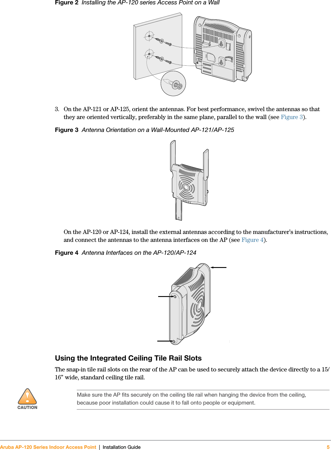
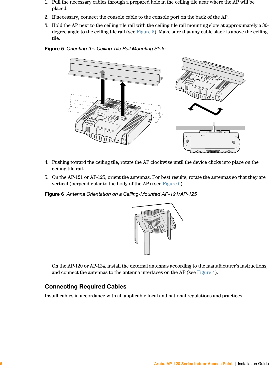
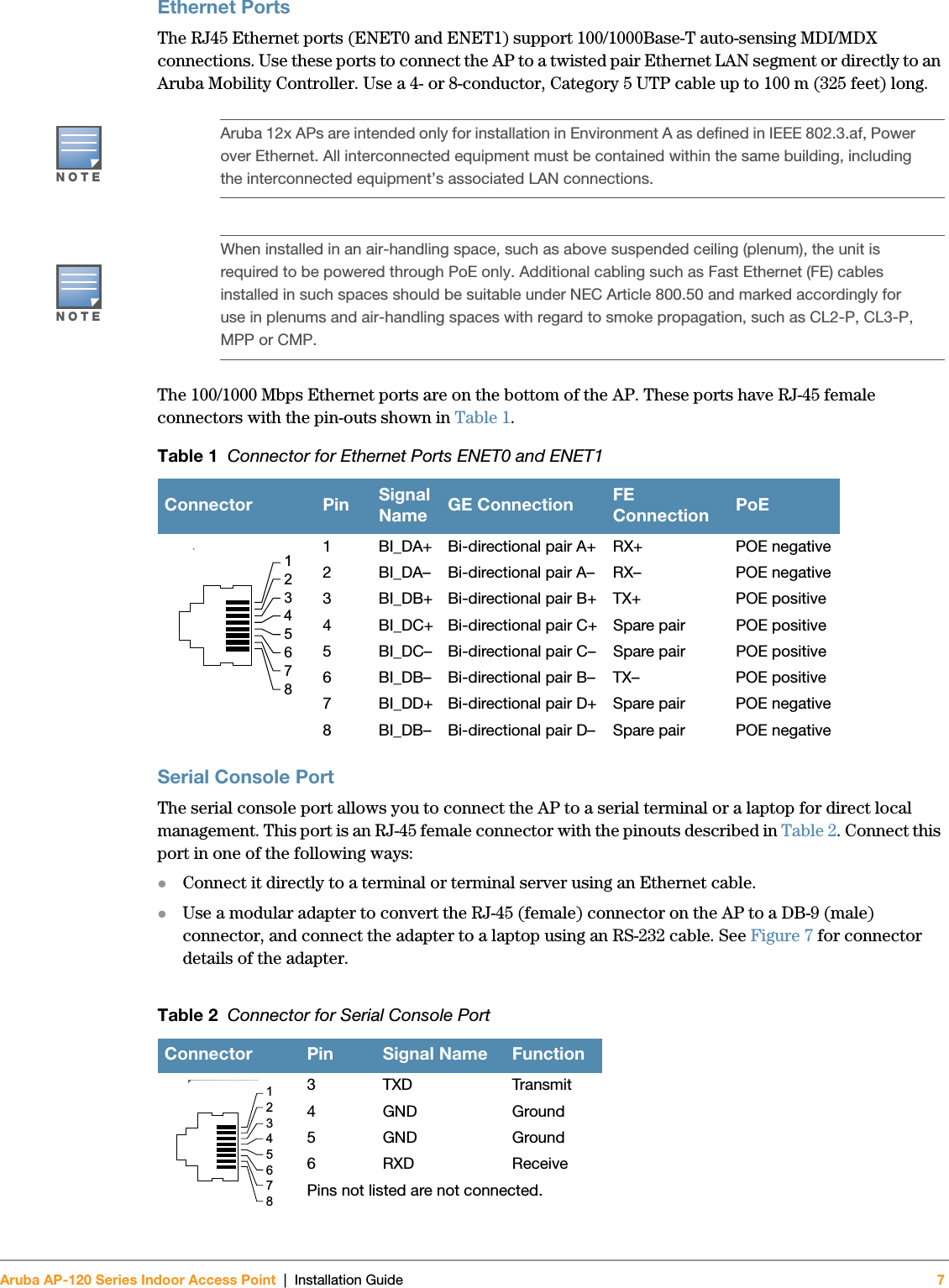
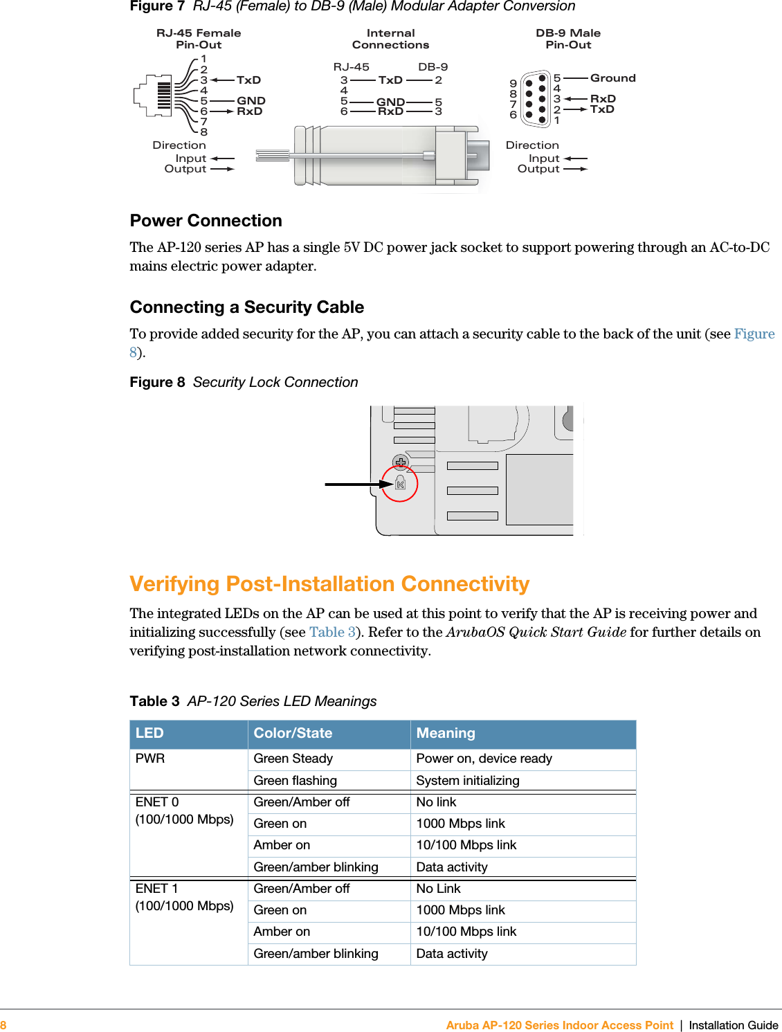
Installation Guide
2.
Regulatory Addendum
Installation Guide
Navigation menu
Upload a User Manual
Namespaces
Wiki Guide
HTML
PDF
Info
Views
User Manual
Discussion / Help
Navigation