Hewlett Packard Enterprise AP124125SDR Aruba AP124 and AP125 Access Point User Manual 12x AP IG 02
Aruba Networks, Inc. Aruba AP124 and AP125 Access Point 12x AP IG 02
Contents
- 1. Users Manual
- 2. Safety and Regulatory Addendum
Users Manual
Aruba AP-120 Series Indoor Access Point
Installation Guide
0510457-02 | December 2007 1
About the Aruba AP-120 Series Access Points
The Aruba AP-120 series of wireless access points support the imminent IEEE 802.11n (currently draft
2.0) standard for high-performance WLAN. These access points use MIMO (Multiple-in, Multiple-out)
technology and other high-throughput mode techniques to deliver high-performance, pre-802.11n
2.4GHz and 5GHz functionality while simultaneously supporting existing 802.11a/b/g wireless services.
The AP-120 series access points are available in versions with single or dual radios and with integrated
antennas or RP-SMA interfaces that support detachable antennas. The AP-120 series access points work
only in conjunction with an Aruba Mobility Controller.
The Aruba AP-120 series access points provide the following capabilities:
zWireless transceiver
zProtocol-independent networking functionality
zIEEE 802.11a/b/g or 802.11n operation as a wireless access point
zIEEE 802.11a/b/g or 802.11n operation as a wireless air monitor
zCompatibility with IEEE 802.3af PoE as well as high power over Ethernet pre-standards
(PoE + / 802.3at)
zCentral management configuration, and upgrades through an Aruba Mobility Controller
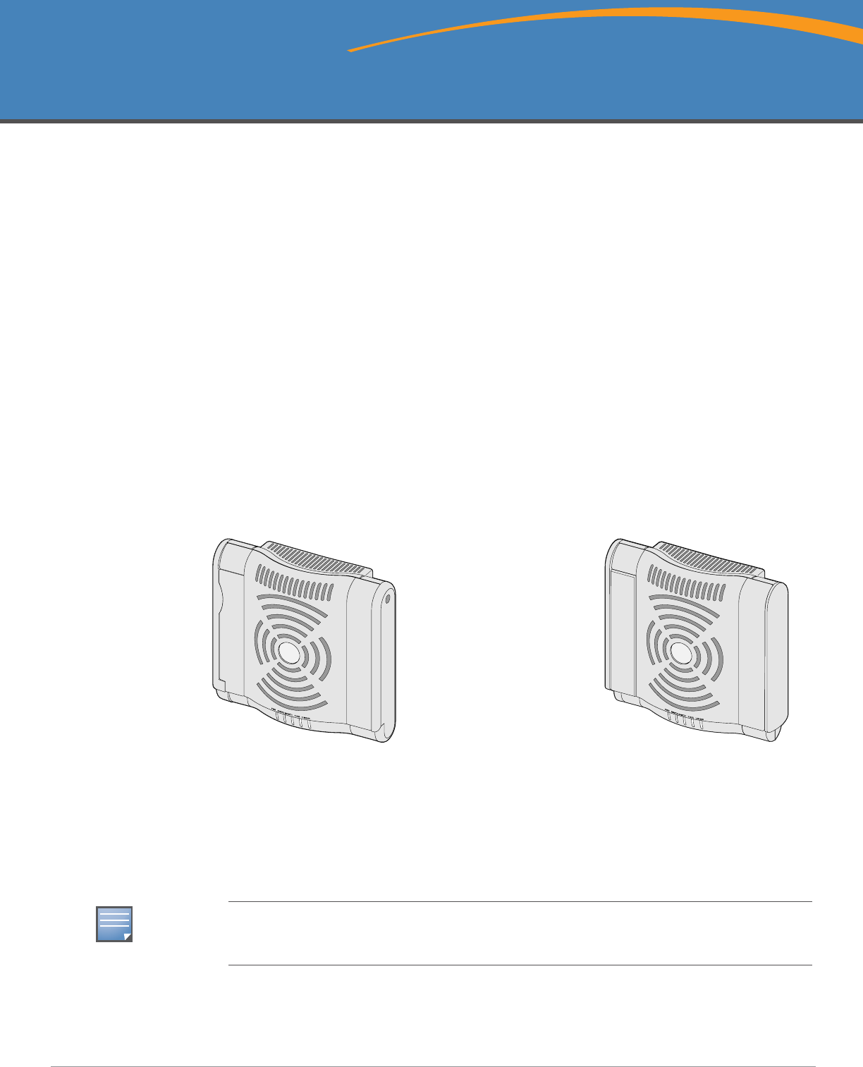
Figure 1 AP-120 Series Access Points
Package Contents
zAP-120 series access point
zInstallation guide (this document)
ap12_001
AP-120/124
(
3 x RP-SMA interfaces for detachable antennas)
AP-121/125
(3 x integrated dual-band antennas)
NOTE
Inform your supplier if there are any incorrect, missing, or damaged parts. If possible, retain the
carton, including the original packing materials. Use these materials to repack and return the unit to
the supplier if needed.
2Aruba AP-120 Series Indoor Access Point | Installation Guide
Before You Begin
WLAN Planning
Determine how many Aruba APs are needed for your wireless network deployment and where they will
be installed. You can easily accomplish this planning using Aruba’s automated RF Plan site-survey
software (available separately). This process is considered WLAN or RF planning and should have been
completed during the master Aruba Mobility Controller installation and configuration. In typical Aruba
installations, the mobility controllers are configured and installed before the APs.
For WLAN planning assistance, refer to the Indoor Access Points: Site Survey and Planning Pre-
Deployment Guide and the RF Plan Installation and User Guide.
Pre-Installation Network Requirements
After WLAN planning is complete and the appropriate products and their placement have been
determined, the Aruba Mobility Controller(s) must be installed and initial setup performed before the
Aruba Access Points are deployed.
For initial setup of the Mobility Controller, refer to the ArubaOS Quick Start Guide for the software
version installed on your controller.
Pre-Installation Checklist
Before installing your AP-120 series access point, be sure that you have the following:
zFor the AP-120/AP-124: External antennas as specified in the network deployment plan
zCAT5 UTP cable of required length
zOne of the following power sources:
IEEE 802.3af-compliant Power over Ethernet (PoE) source
Supports full functionality for AP-120/AP-121; supports reduced functionality for AP-124/AP-125
IEEE Power Over Ethernet + (PoE+) source output at 56Volts @ 350mA
The POE source can be any power source equipment (PSE) controller or midspan PSE device
Aruba AP AC-DC adapter kit (sold separately)
zAruba Mobility Controller provisioned on the network:
Layer 2/3 network connectivity to your access point
One of the following network services:
zAruba Discovery Protocol (ADP)
zDNS server with an “A” record
zDHCP Server with vendor-specific options
Summary of the Setup Process
NOTE
Additional mounting kits for use with the AP-120 series access points are sold separately. Contact
your Aruba sales representative for details.
NOTE
It is important that you verify the items listed under Pre-Installation Checklist before you attempt to
set up and install an AP-120 series AP.
Aruba AP-120 Series Indoor Access Point | Installation Guide 3
Successful setup of an AP-120 series access point consists of four tasks, which must be performed in
this order:
1. Verify pre-installation connectivity.
2. Identify the specific installation location for each AP.
3. Install each AP.
4. Verify post-installation connectivity.
5. Configure each AP.
Verifying Pre-Installation Connectivity
Before you install APs in a network environment, make sure that the APs will be able to locate and
connect to the Mobility Controller when powered on.
Specifically, you must verify the following conditions:
zWhen connected to the network, each AP is assigned a valid IP address
zAPs are able to locate the Mobility Controller (Mobility Controller Discovery)
Refer to the ArubaOS Quick Start Guide for instructions on locating and connecting to the Mobility
Controller.
Identifying Specific Installation Locations
You can mount the AP-120 series access point on a wall or on the ceiling. Use the AP placement map
generated by Aruba’s RF Plan software application to determine the proper installation location(s).
Each location should be as close as possible to the center of the intended coverage area and should be
free from obstructions or obvious sources of interference. These RF absorbers/reflectors/interference
sources will impact RF propagation and should have been accounted for during the planning phase and
adjusted for in RF plan.
NOTE
Aruba Networks, in compliance with governmental requirements, has designed the AP-120 series
access points so that only authorized network administrators can change the settings. For more
information about AP configuration, refer to the ArubaOS Quick Start Guide and Aruba OS User
Guide.
!
CAUTION
Access points are radio transmission devices and as such are subject to governmental regulation.
Network administrators responsible for the configuration and operation of access points must
comply with local broadcast regulations. Specifically, access points must use channel assignments
appropriate to the location in which the access point will be used.
!
CAUTION
RF Radiation Exposure Statement: This equipment complies with FCC RF radiation exposure
limits. This equipment should be installed and operated with a minimum distance of 13.78 inches
(35 cm) between the radiator and your body for 2.4 GHz and 5 GHz operations. This transmitter
must not be co-located or operating in conjunction with any other antenna or transmitter. When
operated in the 5.15 to 5.25 GHz frequency range, this device is restricted to indoor use to reduce
the potential for harmful interference with co-channel Mobile Satellite Systems.
4Aruba AP-120 Series Indoor Access Point | Installation Guide
Unidentified Known RF Absorbers/Reflectors/Interference Sources
Identifying known RF absorbers, reflectors, and interference sources while in the field during the
installation phase is critical. Make sure that these sources are taken into consideration when you attach
an AP to its fixed location.
RF absorbers include:
zCement/concrete: Old concrete has high levels of water dissipation, which dries out the concrete,
allowing for potential RF propagation. New concrete has high levels of water concentration within
the concrete, blocking RF signals.
zNatural Items: Fish tanks, water fountains, ponds, and trees
zBrick
RF reflectors include:
zMetal Objects: Metal pans between floors, rebar, fire doors, air conditioning/heating ducts, mesh
windows, blinds, chain link fences (depending on aperture size), refrigerators, racks, shelves, and
filing cabinets
zDo not place an AP between two air conditioning/heating ducts. Make sure that APs are placed
below ducts to avoid RF disturbances.
RF interference sources include:
zMicrowave ovens and other 2.4 or 5 GHz objects (such as cordless phones)
zLunch rooms and call centers with cordless headsets
Installing the AP
Using the Integrated Wall-Mounting Slots
The keyhole-shaped slots on the back of the AP can be used to attach the device upright to an indoor
wall or shelf. When you choose the mounting location, allow additional space at the right of the unit for
cables.
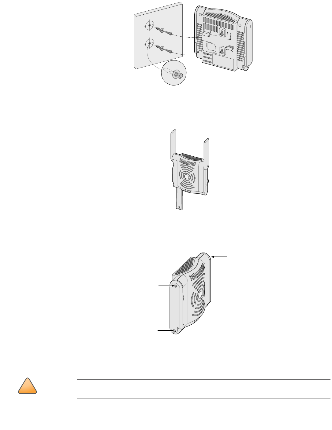
1. At the mounting location, install two screw on the wall or shelf, 1 7/8 inches (4.7 cm) apart. If you
are attaching the device to drywall, Aruba recommends using appropriate wall anchors (not
included).
2. Align the mounting slots on the rear of the AP over the screws and slide the unit into place (see
Figure 2).
NOTE
Service to all Aruba Networks products should be performed by trained service personnel only.
NOTE
For product dimensions, see Product Specifications in this guide. Allow 2 inches (5 cm) of additional
space at the right side of the installed unit for cables, and make sure enough space is available for
antenna articulation.
Aruba AP-120 Series Indoor Access Point | Installation Guide 5
Figure 2 Installing the AP-120 series Access Point on a Wall
3. On the AP-121 or AP-125, orient the antennas. For best performance, swivel the antennas so that
they are oriented vertically, preferably in the same plane, parallel to the wall (see Figure 3).
Figure 3 Antenna Orientation on a Wall-Mounted AP-121/AP-125
On the AP-120 or AP-124, install the external antennas according to the manufacturer’s instructions,
and connect the antennas to the antenna interfaces on the AP (see Figure 4).
Figure 4 Antenna Interfaces on the AP-120/AP-124
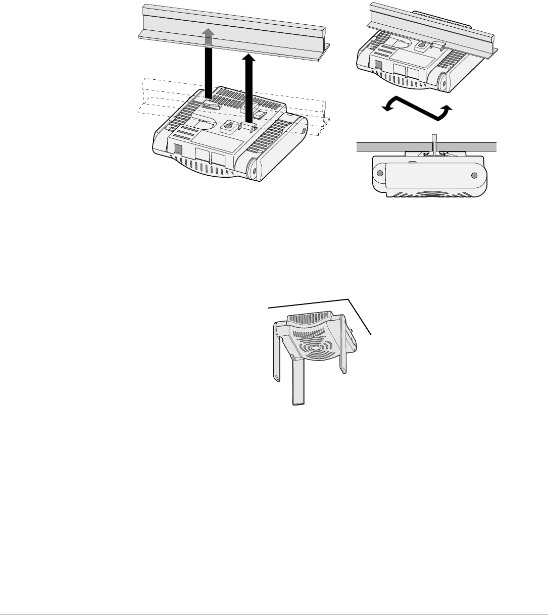
Using the Integrated Ceiling Tile Rail Slots
The snap-in tile rail slots on the rear of the AP can be used to securely attach the device directly to a 15/
16” wide, standard ceiling tile rail.
a
p
!
CAUTION
Make sure the AP fits securely on the ceiling tile rail when hanging the device from the ceiling,
because poor installation could cause it to fall onto people or equipment.
6Aruba AP-120 Series Indoor Access Point | Installation Guide
1. Pull the necessary cables through a prepared hole in the ceiling tile near where the AP will be
placed.
2. If necessary, connect the console cable to the console port on the back of the AP.
3. Hold the AP next to the ceiling tile rail with the ceiling tile rail mounting slots at approximately a 30-
degree angle to the ceiling tile rail (see Figure 5). Make sure that any cable slack is above the ceiling
tile.
Figure 5 Orienting the Ceiling Tile Rail Mounting Slots
4. Pushing toward the ceiling tile, rotate the AP clockwise until the device clicks into place on the
ceiling tile rail.
5. On the AP-121 or AP-125, orient the antennas. For best results, rotate the antennas so that they are
vertical (perpendicular to the body of the AP) (see Figure 6).
Figure 6 Antenna Orientation on a Ceiling-Mounted AP-121/AP-125
On the AP-120 or AP-124, install the external antennas according to the manufacturer’s instructions,
and connect the antennas to the antenna interfaces on the AP (see Figure 4).
Connecting Required Cables
Install cables in accordance with all applicable local and national regulations and practices.
ap
1
Aruba AP-120 Series Indoor Access Point | Installation Guide 7
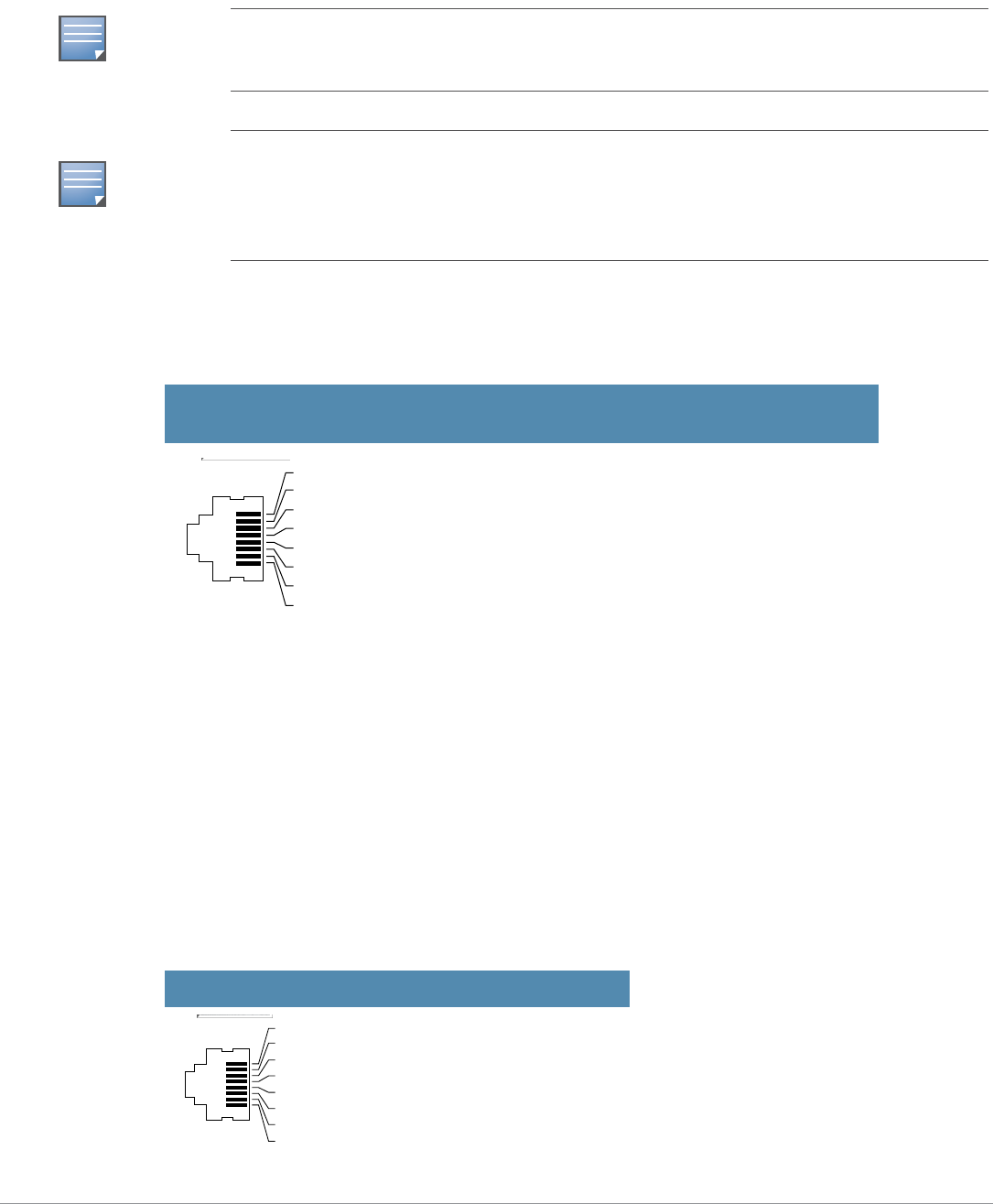
Ethernet Ports
The RJ45 Ethernet ports (ENET0 and ENET1) support 100/1000Base-T auto-sensing MDI/MDX
connections. Use these ports to connect the AP to a twisted pair Ethernet LAN segment or directly to an
Aruba Mobility Controller. Use a 4- or 8-conductor, Category 5 UTP cable up to 100 m (325 feet) long.
The 100/1000 Mbps Ethernet ports are on the bottom of the AP. These ports have RJ-45 female
connectors with the pin-outs shown in Table 1.
Serial Console Port
The serial console port allows you to connect the AP to a serial terminal or a laptop for direct local
management. This port is an RJ-45 female connector with the pinouts described in Table 2. Connect this
port in one of the following ways:
zConnect it directly to a terminal or terminal server using an Ethernet cable.
zUse a modular adapter to convert the RJ-45 (female) connector on the AP to a DB-9 (male)
connector, and connect the adapter to a laptop using an RS-232 cable. See Figure 7 for connector
details of the adapter.
NOTE
Aruba 12x APs are intended only for installation in Environment A as defined in IEEE 802.3.af, Power
over Ethernet. All interconnected equipment must be contained within the same building, including
the interconnected equipment’s associated LAN connections.
NOTE
When installed in an air-handling space, such as above suspended ceiling (plenum), the unit is
required to be powered through PoE only. Additional cabling such as Fast Ethernet (FE) cables
installed in such spaces should be suitable under NEC Article 800.50 and marked accordingly for
use in plenums and air-handling spaces with regard to smoke propagation, such as CL2-P, CL3-P,
MPP or CMP.
Table 1 Connector for Ethernet Ports ENET0 and ENET1
Connector Pin Signal
Name GE Connection FE
Connection PoE
1 BI_DA+ Bi-directional pair A+ RX+ POE negative
2 BI_DA– Bi-directional pair A– RX– POE negative
3 BI_DB+ Bi-directional pair B+ TX+ POE positive
4 BI_DC+ Bi-directional pair C+ Spare pair POE positive
5 BI_DC– Bi-directional pair C– Spare pair POE positive
6 BI_DB– Bi-directional pair B– TX– POE positive
7 BI_DD+ Bi-directional pair D+ Spare pair POE negative
8 BI_DB– Bi-directional pair D– Spare pair POE negative
Table 2 Connector for Serial Console Port
Connector Pin Signal Name Function
3TXD Transmit
4GND Ground
5GND Ground
6RXD Receive
Pins not listed are not connected.
1
2
3
4
5
6
7
8
1
2
3
4
5
6
7
8
8Aruba AP-120 Series Indoor Access Point | Installation Guide
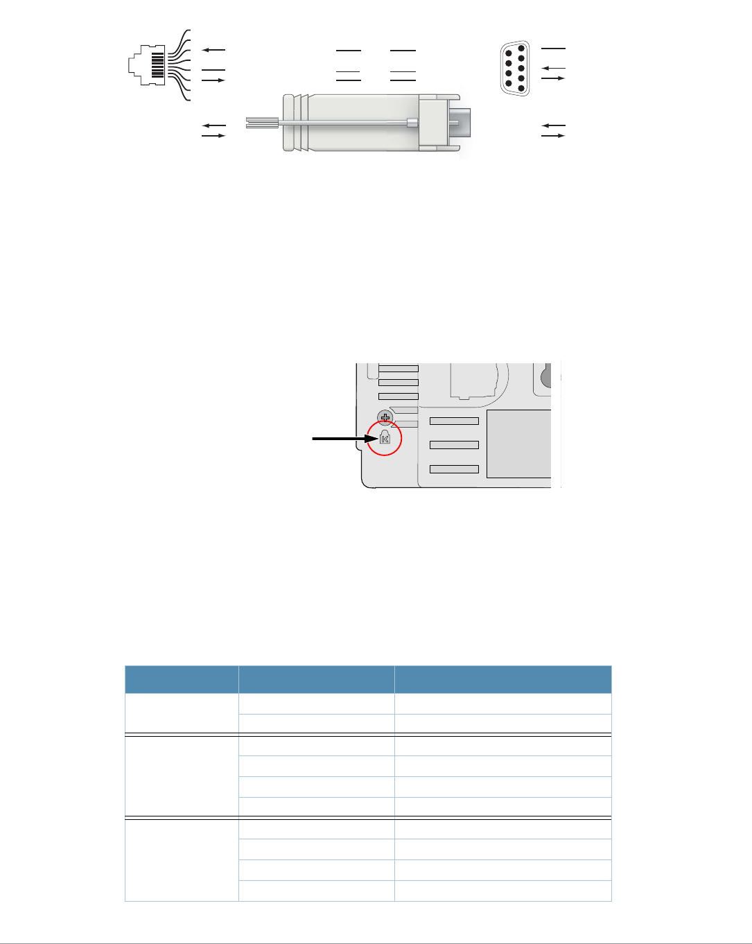
Figure 7 RJ-45 (Female) to DB-9 (Male) Modular Adapter Conversion
Power Connection
The AP-120 series AP has a single 5V DC power jack socket to support powering through an AC-to-DC
mains electric power adapter.
Connecting a Security Cable
To provide added security for the AP, you can attach a security cable to the back of the unit (see Figure
8).
Figure 8 Security Lock Connection
Verifying Post-Installation Connectivity
The integrated LEDs on the AP can be used at this point to verify that the AP is receiving power and
initializing successfully (see Table 3). Refer to the ArubaOS Quick Start Guide for further details on
verifying post-installation network connectivity.
Table 3 AP-120 Series LED Meanings
LED Color/State Meaning
PWR Green Steady Power on, device ready
Green flashing System initializing
ENET 0
(100/1000 Mbps)
Green/Amber off No link
Green on 1000 Mbps link
Amber on 10/100 Mbps link
Green/amber blinking Data activity
ENET 1
(100/1000 Mbps)
Green/Amber off No Link
Green on 1000 Mbps link
Amber on 10/100 Mbps link
Green/amber blinking Data activity
3
4
5
2
5
63
RJ-45 DB-9
Internal
Connections
TxD
GND
RxD
1
2
3
4
5
6
7
8
TxD
GND
RxD
RJ-45 Female
Pin-Out
Direction
Input
Output
DB-9 Male
Pin-Out
TxD
RxD
Ground
5
4
3
2
1
9
8
7
6
Direction
Input
Output

Aruba AP-120 Series Indoor Access Point | Installation Guide 9
Configuring the AP-12x
AP Provisioning/Reprovisioning
Provisioning parameters are unique to each AP. These local AP parameters are initially configured on
the Mobility Controller which are then pushed out to the AP and stored on the AP itself. Aruba
recommends that provisioning settings be configured via the ArubaOS Web UI only. Refer to the
ArubaOS User Guide for complete details.
AP Configuration
Configuration parameters are network or controller specific and are configured and stored on the
Mobility Controller. Network configuration settings are pushed out to the AP(s) but remain stored on
the Mobility Controller.
Configuration settings can be configured via the ArubaOS Web UI, ArubaOS CLI, or Aruba MMS. Refer
to their respective guides for further details: the ArubaOS User Guide or Aruba Mobility Management
System User Guide.
Product Specifications
Mechanical
zDimensions (antenna stowed) (HxWxD):
4.9 inches x 5. 13 inches x 2 inches
12.4 cm x 13 cm x 5.1 cm
zWeight: 15 oz/0.42 kg
zShipping Dimensions:
9.5 inches x 7.25 inches x 4.5 inches
24.1 cm x 18.4 cm x 11.4 cm
zTemperature:
Operating: 0ºC to 50ºC (32ºF to 122ºF)
Storage: –10ºC to 70ºC (14ºF to 158ºF)
zRelative Humidity: 5% to 95% non-condensing
zAltitude: 8,000 ft @ 28ºC (82.4ºF)
zMounting: Wall, ceiling, or desktop mountable
zAntennas:
3 integrated articulating dual-band antenna elements (AP-121, AP-125)
3 RP-SMA interfaces for external antennas (AP-120, AP-124)
zVisual Status Indicators (LEDs): See Table 3
11A/N Amber on Wireless link is legacy 11a.
Green on Wireless link is 11n 5Ghz band.
11B/G/N Amber Wireless link is legacy 11b or 11g.
Green Wireless link is 11n 2.4Ghz band.
Table 3 AP-120 Series LED Meanings
LED Color/State Meaning

10 Aruba AP-120 Series Indoor Access Point | Installation Guide
Electrical
Ethernet:
2 x 100/1000 Base-T auto-sensing Ethernet RJ-45 Interfaces
MDI/MDX
IEEE 802.3 (10Base-T), IEEE 802.3u (100Base-T). IEEE 802.3ab (1000Base-T)
Power over Ethernet (IEEE 802.3af compliant), 48V DC/200mA (see Table 1 for pin
configuration)
zPower:
5 VDC power interface, supports powering through an AC-to-DC mains electric power adapter
POE support on Ethernet ports:
– 802.3af-compliant POE sourcing devices
– POE+ (56 V @ 350 mA)
Wireless LAN
zNetwork Standards: IEEE 802.11b, IEEE 802.11g, IEEE 802.11a, and IEEE 802.11n
zAntenna Type:
Integrated 802.11a/b/g/n omni-directional high-gain antenna
Detachable 802.11a/b/g/n omni-directional high-gain antenna
zAntenna Gain (Integrated Antennas):
2.4 – 2.5 GHz/3.2 dBi (max)
5.180 – 5.825 GHz/5.2 dBi (max)
zRadio Technology:
Orthogonal Frequency Division Multiplexing (OFDM)
Direct Sequence Spread Spectrum (DSSS)
zRadio Modulation Type:
802.11b - CCK, BPSK, QPSK
802.11g - CCK, BPSK, QPSK,16-QAM, 64-QAM
802.11a - BPSK, QPSK,16-QAM, 64-QAM
802.11n draft 2.0
zMedia Access Control: CSMA/CA with ACK
zSupported Frequency Bands 2.4GHz:
2.400 ~ 2.4835GHz (Global), channels country specific
zSupported Frequency Bands 5GHz:
5.150 ~ 5.250GHz (low band), country-specific
5.250 ~ 5.350GHz (mid band), country-specific
5.470 ~ 5.725GHz (Europe), country-specific
5.725 ~ 5.825GHz GHz (high band), country-specific
zData Rates:
802.11b - 1, 2, 5.5, 11 Mbps per channel
802.11g - 6, 9, 12, 18, 24, 36, 48 and 54 Mbps per channel
802.11a - 6, 9, 12, 18, 24, 36, 48 and 54 Mbps per channel
802.11n - Data rate MCS0 – MCS15 (from 6.5 Mbps to 300 Mbps)
Aruba AP-120 Series Indoor Access Point | Installation Guide 11
Safety and Regulatory Compliance
Aruba Networks provides a multi-language document that contains country-specific restrictions and
additional safety and regulatory information for all Aruba access points. This document can be viewed
or downloaded from the following location:
www.arubanetworks.com/pdf/0510272-01.pdf
Proper Disposal of Aruba Equipment
For the most current information about Global Environmental Compliance and Aruba products, see our
website at www.arubanetworks.com.
Waste of Electrical and Electronic Equipment
Aruba products at end of life are subject to separate collection and treatment in the
EU Member States, Norway, and Switzerland and therefore are marked with the
symbol shown at the left (crossed-out wheelie bin). The treatment applied at end of
life of these products in these countries shall comply with the applicable national
laws of countries implementing Directive 2002/96EC on Waste of Electrical and
Electronic Equipment (WEEE).
European Union RoHS
Aruba products also comply with the EU Restriction of Hazardous Substances
Directive 2002/95/EC (RoHS). EU RoHS restricts the use of specific hazardous
materials in the manufacture of electrical and electronic equipment. Specifically,
restricted materials under the RoHS Directive are Lead (including Solder used in printed circuit
assemblies), Cadmium, Mercury, Hexavalent Chromium, and Bromine. Some Aruba products are
subject to the exemptions listed in RoHS Directive Annex 7 (Lead in solder used in printed circuit
assemblies). Products and packaging will be marked with the “RoHS” label shown at the left indicating
conformance to this Directive.
!
CAUTION
RF Radiation Exposure Statement: This equipment complies with FCC RF radiation exposure
limits. This equipment should be installed and operated with a minimum distance of 13.78 inches
(35 cm) between the radiator and your body for 2.4 GHz and 5 GHz operations. This transmitter
must not be co-located or operating in conjunction with any other antenna or transmitter. When
operated in the 5.15 to 5.25 GHz frequency range, this device is restricted to indoor use to reduce
the potential for harmful interference with co-channel Mobile Satellite Systems.
© 2007 Aruba Networks, Inc. All rights reserved.
www.arubanetworks.com
1322 Crossman Avenue
Sunnyvale, California 94089
Phone: 408.227.4500
Fax 408.227.4550
12 Aruba AP-120 Series Indoor Access Point | Installation Guide
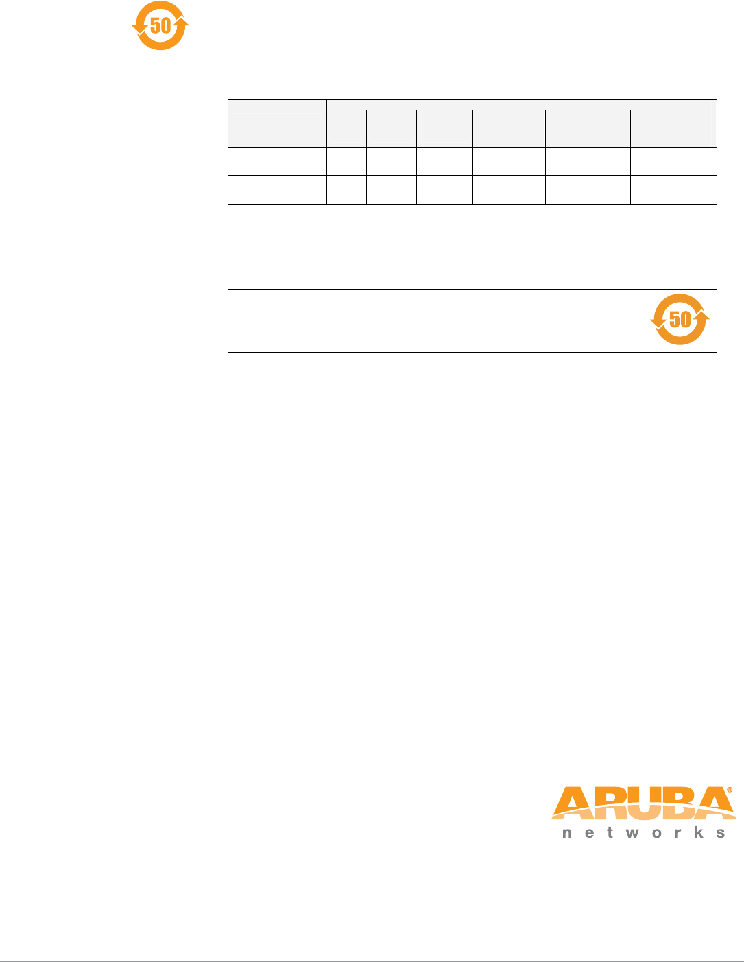
China RoHS
Aruba products also comply with China environmental declaration requirements and are
labeled with the “EFUP 50” label shown at the left.
Ქኂ‛ ჿ䋼
Hazardous Materials Declaration
Ქኂ‛䋼ᚗర⚛
Hazardous Substances)
ㇱઙฬ⒓
(Parts)
䪙
Lead
(Pb)
ᳮ
Mercury
(Hg)
䬝
Cadmium
(Cd)
ચ䫀
Chromium VI
Compounds
(Cr6+)
ᄙ⒈ 㘨 ⧶
Polybrominated
Biphenyls
(PBB)
ᄙ⒈ੑ䝮
⧶
Polybrominated
Diphenyl Ether
(PBDE)
⬉〝᧼
PCA Board XO O O O O
᪾㒘ઙ
Mechanical
Subassembly
XO O O O O
O:␜䆹Ქኂ‛䋼䆹ㇱઙᚲဋ䋼᧚ᢱਛ⊛㊂ဋSJ/T11363-2006ᷛಎ㾘ቯ⊛㒢㊂ⷐ᳞એਅޕ
This component does not contain this hazardous substance above the maximum concentration values in homogeneous materials
specified in the SJ/T11363-2006 Industry Standard.
X: ␜䆹Ქኂ‛䋼⥋ዋ䆹ㇱઙ⊛ᨱ৻ဋ䋼᧚ᢱਛ⊛㊂SJ/T11363-2006ᷛಎ㾘ቯ⊛㒢㊂ⷐ᳞ޕ
This component does contain this hazardous substance above the maximum concentration values in homogeneous materials specified
in the SJ/T11363-2006 Industry Standard.
ᇍ䫔ଂП᮹ⱘ᠔ଂѻકᴀ㸼ᰒ⼎կᑨ䫒ⱘ⬉ᄤֵᙃѻકৃ㛑ࣙ䖭ѯ⠽䋼ޕ
This table shows where these substances may be found in the supply chain of electronic information products, as of the date of sale of
the enclosed product.
ℸᷛᖫЎ䩜ᇍ᠔⍝ঞѻકⱘ⦃ֱՓ⫼ᳳᷛᖫ
ᶤѯ䳊䚼ӊӮ᳝ϔϾϡৠⱘ⦃ֱՓ⫼ᳳ՟བ⬉∴ऩܗഫ䌈݊ѻકϞ
ℸ⦃ֱՓ⫼ᳳ䰤া䗖⫼ѢѻકᰃѻકݠЁ᠔㾘ᅮⱘᴵӊϟᎹ
The Environment- Friendly Use Period (EFUP) for all enclosed products and their parts are per the
symbol shown here. The Environment- Friendly Use Period is valid only when the product is operated
under the conditions defined in the product manual.