Hewlett Packard Enterprise AP134135 IEEE 802.11a/b/g/n Access Point User Manual AP130 IG Rev01
Aruba Networks, Inc. IEEE 802.11a/b/g/n Access Point AP130 IG Rev01
Contents
- 1. Professional Installation Guide
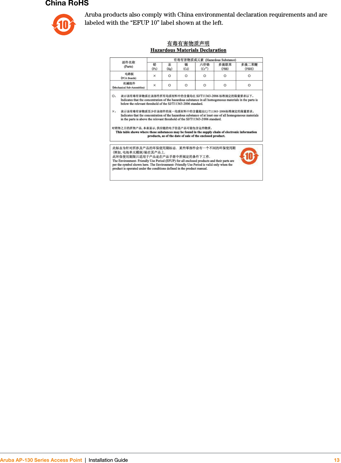
- 2. Installation Guide
- 3. User Manual
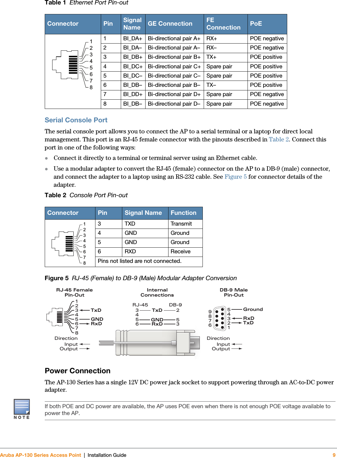
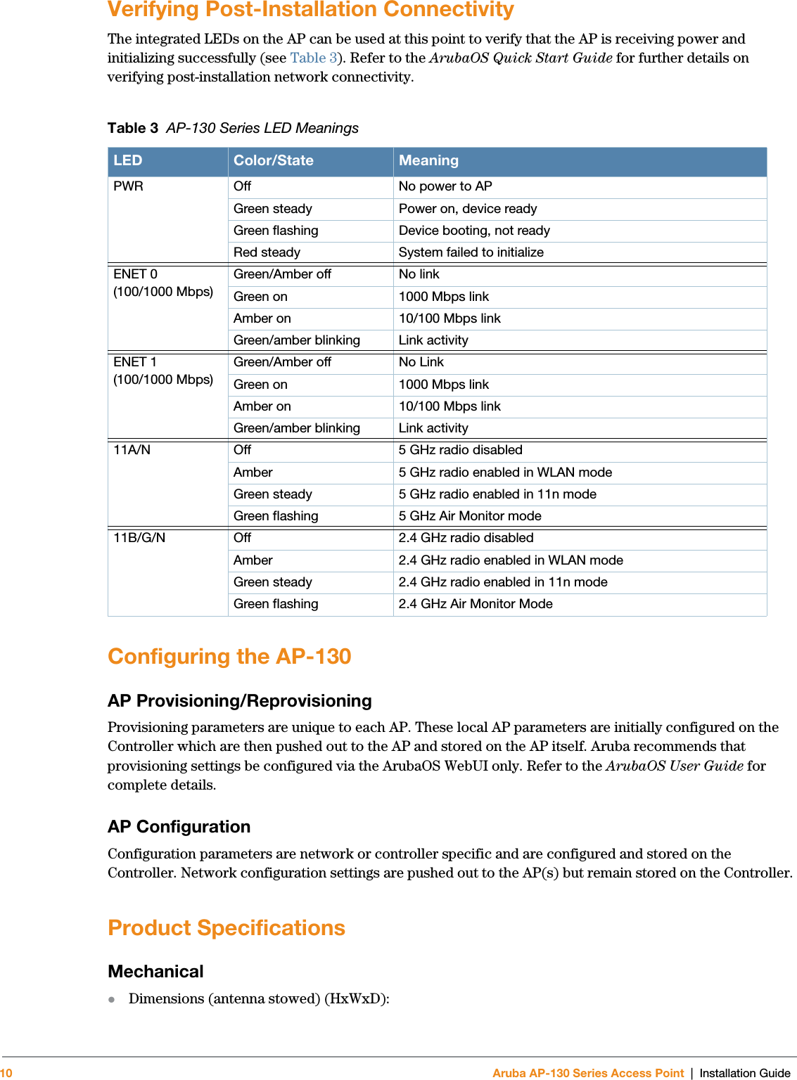
User Manual