Hewlett Packard Enterprise AP175 802.11 a/b/g/n Wireless Access Point User Manual AP 175 IG Rev01
Aruba Networks, Inc. 802.11 a/b/g/n Wireless Access Point AP 175 IG Rev01
Contents
- 1. User Guide
- 2. Users Guide
User Guide
Aruba AP-175 Outdoor Access Point
Installation Guide
0510795-01 | September 2010 1
The Aruba AP-175 is a resilient, environmentally hardened, outdoor rated, dual-radio, dual-band IEEE
802.11 a/b/g/n wireless access point. This outdoor access point is part of Aruba’s comprehensive wireless
network solution. The AP-175 works only in conjunction with an Aruba controller and each AP can be
centrally managed, configured, and upgraded through the controller.
There are three versions of the AP-175, which mainly differ in the way they receive power.
zAP-175P: PoE+ powered (802.3at)
zAP-175AC: AC powered (100 - 240 VAC)
zAP-175DC: DC powered (12 - 48 VDC)
Guide Overview
z"AP-175 Hardware Overview" on page2 provides a detailed hardware overview of the three AP-175
models.
z"Outdoor Planning and Deployment Considerations" on page5 provides key questions to ask and items
to consider when deploying an outdoor wireless network.
z"Installing the AP-175" on page9 describes the multi-step process for a successful installation and
deployment of an AP-175.
z"Safety and Regulatory Compliance" on page15 provides an overview of safety and regulatory
compliance information.
AP-175 Operations
zWireless access point (IEEE 802.11 a/b/g/n)
zWireless air monitor (IEEE 802.11 a/b/g/n)
zEnterprise mesh point
zEnterprise mesh portal
zProtocol-independent networking functionality
zAP-175P: IEEE 802.3at Power over Ethernet+ (PoE+) compatible
zAP-175AC and AP-175DC: IEEE 802.3af Power Sourcing Equipment (PSE) device
NOTE
The AP-175AC/DC can function as a Power Sourcing Equipment (PSE) device by providing power through its
Ethernet port in compliance with the IEEE 802.3af standard.
AP-175-IG-Rev01.fm Page 1 Friday, September 17, 2010 4:27 PM
2Aruba AP-175 Outdoor Access Point | Installation Guide
Package Contents
zAP-175 Access Point
zAP-175 Mounting Bracket
zSolar Shield
zPole Anchors x 2
zM4 x 16 bolts, flat washers, and spring washers x4 (These bolts are attached to the solar shield)
zM6 x 30 bolts, flat washers, and spring washers x2
zM4 x 12 bolt, external-tooth washer, and OT copper lug x1
zM8 x 110 bolt, flat washers, spring washers, and nuts x4
zInstallation Guide
AP-175 Hardware Overview
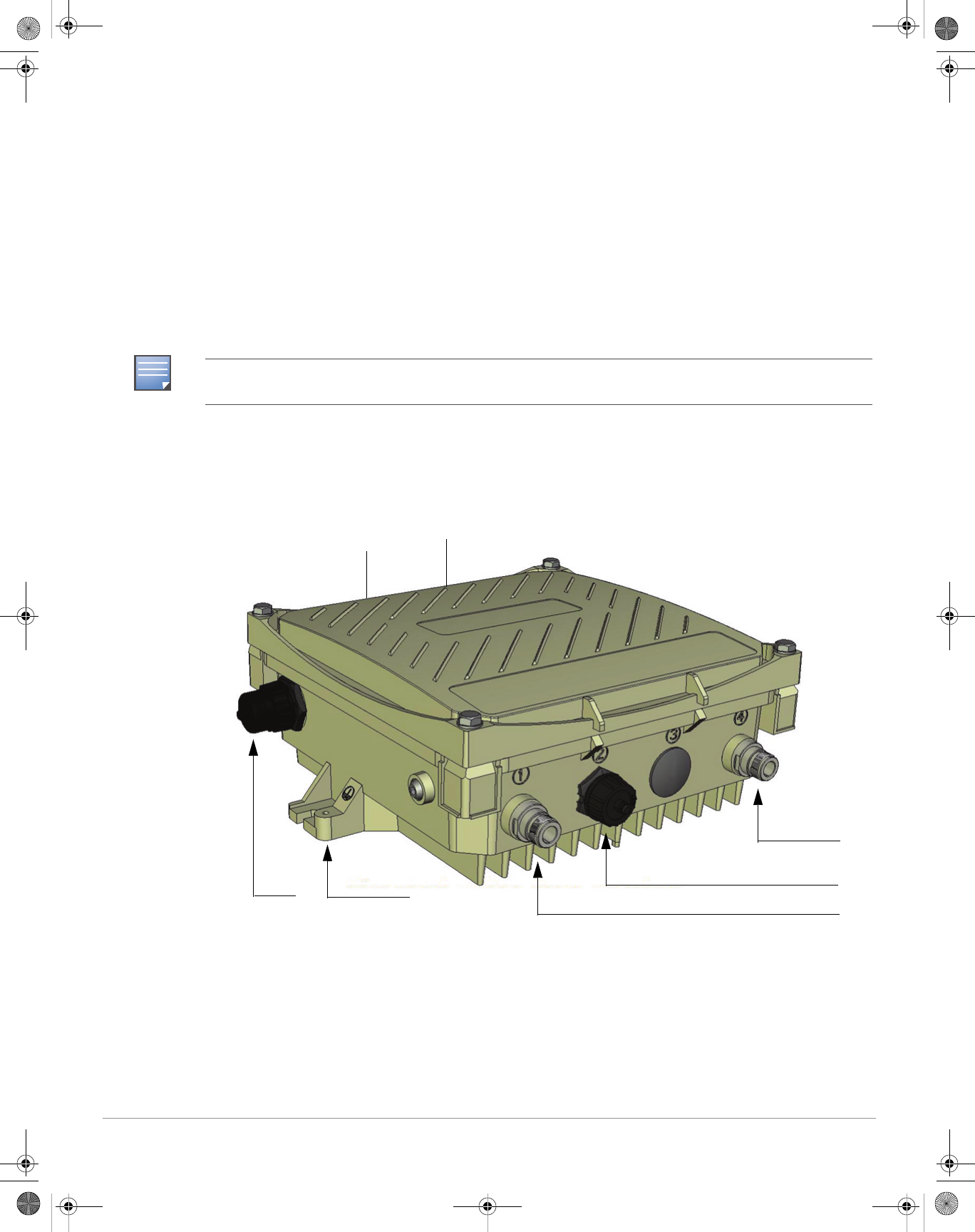
The following section describes the hardware features of the AP-175.
Figure 1 AP-175 Overview
NOTE
Inform your supplier if there are any incorrect, missing, or damaged parts. If possible, retain the carton, including
the original packing materials. Use these materials to repack and return the unit to the supplier if needed.
1 Antenna Interface (Radio 1) 5 Antenna Interface (Radio 0)
2 USB Console Interface 6 Antenna Interface (Radio 1)
3 Reserved (AP-175P) or
Power Interface (AP-175AC and AP-175DC)
7 Ethernet Interface (PoE)
4 Antenna Interface (Radio 0) 8 Grounding Point
2
1
3
4
8
7
65
AP-175-IG-Rev01.fm Page 2 Friday, September 17, 2010 4:27 PM
Aruba AP-175 Outdoor Access Point | Installation Guide 3
Antenna Interface
The AP-175 requires the use of detachable outdoor-rated antennas. Select the correct antenna type to
support the required frequency band (2.4 or 5 GHz) and the desired coverage pattern.
The AP-175 is equipped with four, female N-type antenna interfaces; two on the top of the AP and two on
the bottom. The interfaces are grouped into diversity pairs, one pair is marked R0 (Radio 0) and the other
pair marked as R1 (Radio 1). R0 supports the 5 GHz frequency band and R1 supports the 2.4 GHz radio
band.
USB Console Interface
A USB serial console port is provided for connection to a terminal, allowing direct local management. Use
the following setting to access the terminal:
Power Interface
The type of power interface on your AP-175 depends on which model you have purchased.
zAP-175P: This version does not include a power interface since it is only powered by PoE+ (802.3at).
zAP-175AC: 1x AC power connector
zAP-175DC: 1x DC power connector
Ethernet Interface
The AP-175 is equipped with a 10/100/1000Base-T Gigabit Ethernet port for wired network connectivity. On
the AP-175P, this port also supports IEEE 802.3at Power over Ethernet (PoE), accepting 48 VDC as a
standards-defined powered device (PD) from a power sourcing equipment (PSE) device, such as a PoE
midspan injector. Inversely, the AP-175AC and AP-175DC can act as a PSE device to provide IEEE802.3af
PoE power to devices connected to the Ethernet port.
Grounding Point
Always remember to protect your AP-175 by installing grounding lines. The ground connection must be
complete before connecting power to the AP-175 enclosure. Ensure that the resistance is less than 5 ohm
between the ground termination point and the grounding tier.
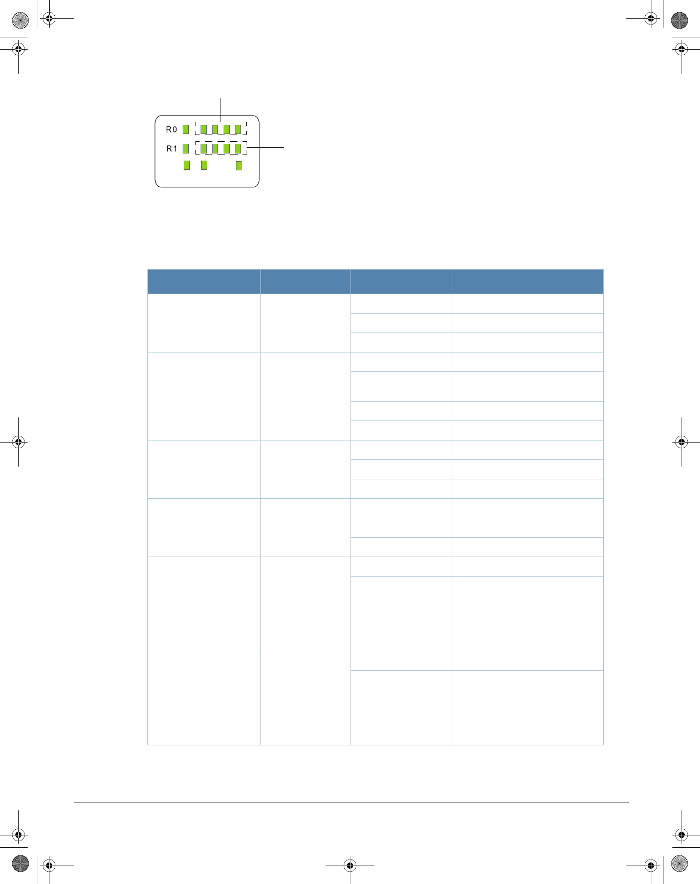
LED Status Indicators
The AP-175 include visual indicators for power, link, and radio status. Additionally, each radio has a four-
LED array that indicates received signal strength (RSSI).
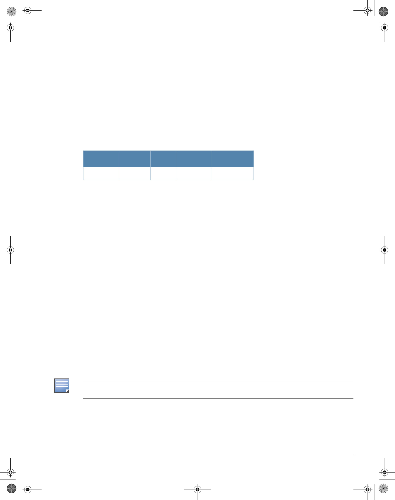
Table 1 Console Settings
Baud Rate Data Bits Parity Stop Bits Flow Control
9600 8 None 1 None
NOTE
The RSSI LED indicators represent varying degrees in the RSSI level. The absence of a signal is indicated by no
LED response, and full signal strength is indicated when all four LEDs are active and lit.
AP-175-IG-Rev01.fm Page 3 Friday, September 17, 2010 4:27 PM
4Aruba AP-175 Outdoor Access Point | Installation Guide
Figure 2 LED Layout
Table 2 lists the meanings of the LEDs on the AP-175 outdoor access points.
Table 2 AP-175 LED Status Indicators
LED Function Indicator Status
P/S AP Power/Ready
Status Off No power to AP
Blinking Device booting, not ready
On Device ready
ENT LAN/Network Link
Status Off Ethernet link unavailable
On (Amber) 10/100 Mbs Ethernet link
negotiated
On (Green) 1000 Mbs Ethernet link negotiated
Blinking Traffic on Ethernet link
R0 Radio 0 Status Off Radio 0 disabled
On (Amber) Radio 0 enabled in WLAN mode
Blinking Air Monitor (AM) mode
R1 Radio 1 Status Off Radio 1disabled
On (Blue) Radio 1 enabled in WLAN mode
Blinking Air Monitor (AM) mode
RSSI (Radio 0) RSSI Level for
Radio 0 Off RSSI disabled/no signal
4 Step Progressive
Bars (Red)
25/50/75/100%
Each bar represents a progressive
increase in signal strength, with 4
bars representing maximum signal
strength (100%).
Minimum data rate: One lit LEDs
Maximum data rate: Four lit LEDs
RSSI (Radio 1) RSSI Level for
Radio 1 Off RSSI disabled/no signal
4 Step Progressive
Bars (Blue)
25/50/75/100%
Each bar represents a progressive
increase in signal strength, with 4
bars representing maximum signal
strength (100%).
Minimum data rate: One lit LEDs
Maximum data rate: Four lit LEDs
P/S ENT
RSSI for Radio 1
RSSI for Radio 0
AP-175-IG-Rev01.fm Page 4 Friday, September 17, 2010 4:27 PM

Aruba AP-175 Outdoor Access Point | Installation Guide 5
Outdoor Planning and Deployment Considerations
Prior to deploying an outdoor wireless network, the environment must be evaluated to plan for a successful
Aruba WLAN deployment. Successfully evaluating the environment enables the proper selection of Aruba
APs and antennas and assists in the determination of their placement for optimal RF coverage. This process
is considered WLAN or RF planning and Aruba’s system engineers can assist in the outdoor planning
process.
Scale Requirements
The potentially immense scale of outdoor deployments requires consideration of factors that may not be as
important in a typical indoor deployment:
zRange (distance): Range or distance between APs must be taken into account during the planning phase.
Available AP mounting locations are often far less flexible in an outdoor environment. Regardless of
these outdoor restrictions, the desired goal is to achieve results similar to an indoor deployment: a
“dense” RF deployment that supports advanced Aruba features, such as ARM, efficient client roaming,
and failover.
zElevation: Proper consideration and planning for elevation differences between APs (AP to AP) and AP
to Client can be critical to success. To plan for these differences in elevation, it is important to
understand the 3D coverage pattern provided by the antennas that will be deployed in the environment.
zNon-Fixed Considerations: The RF environment might change on a day to day basis. Keep non-fixed
items, such as shipping containers, vehicles, and future building construction, in mind when planning for
an outdoor deployment.
Identifying Known RF Absorbers/Reflectors/Interferences Sources
Identifying known RF absorbers/reflectors/interference sources while out in the field during the installation
phase is critical. Even though outdoor environments consist of fewer RF absorbers/reflectors/interference
sources compared to indoor environments, ensure that these sources are identified and taken into
consideration when installing and mounting an AP to its fixed outdoor location.
RF Absorbers
zCement/Concrete
zNatural Items: Trees/vegetation
zBrick
RF Reflectors
zMetal Objects: Roof-installed air-conditioning equipment, chain link fences (depending on aperture
size), other wire fences, or water pipes
RF Interference Sources
zOther 802.11a/b/g/n or broadband access equipment operating nearby
zIndustrial RF welding equipment or other Industrial, Scientific and Medical (ISM) equipment that utilizes
RF to heat or alter the physical properties of materials
zMilitary, Commercial Aviation or Weather Radar Systems
Line of Sight (Radio Path Planning)
A wireless bridge or mesh link requires a “radio line of sight” between the two antennas for optimum
performance. The concept of radio line of sight involves the area along a link through which the bulk of the
AP-175-IG-Rev01.fm Page 5 Friday, September 17, 2010 4:27 PM
6Aruba AP-175 Outdoor Access Point | Installation Guide
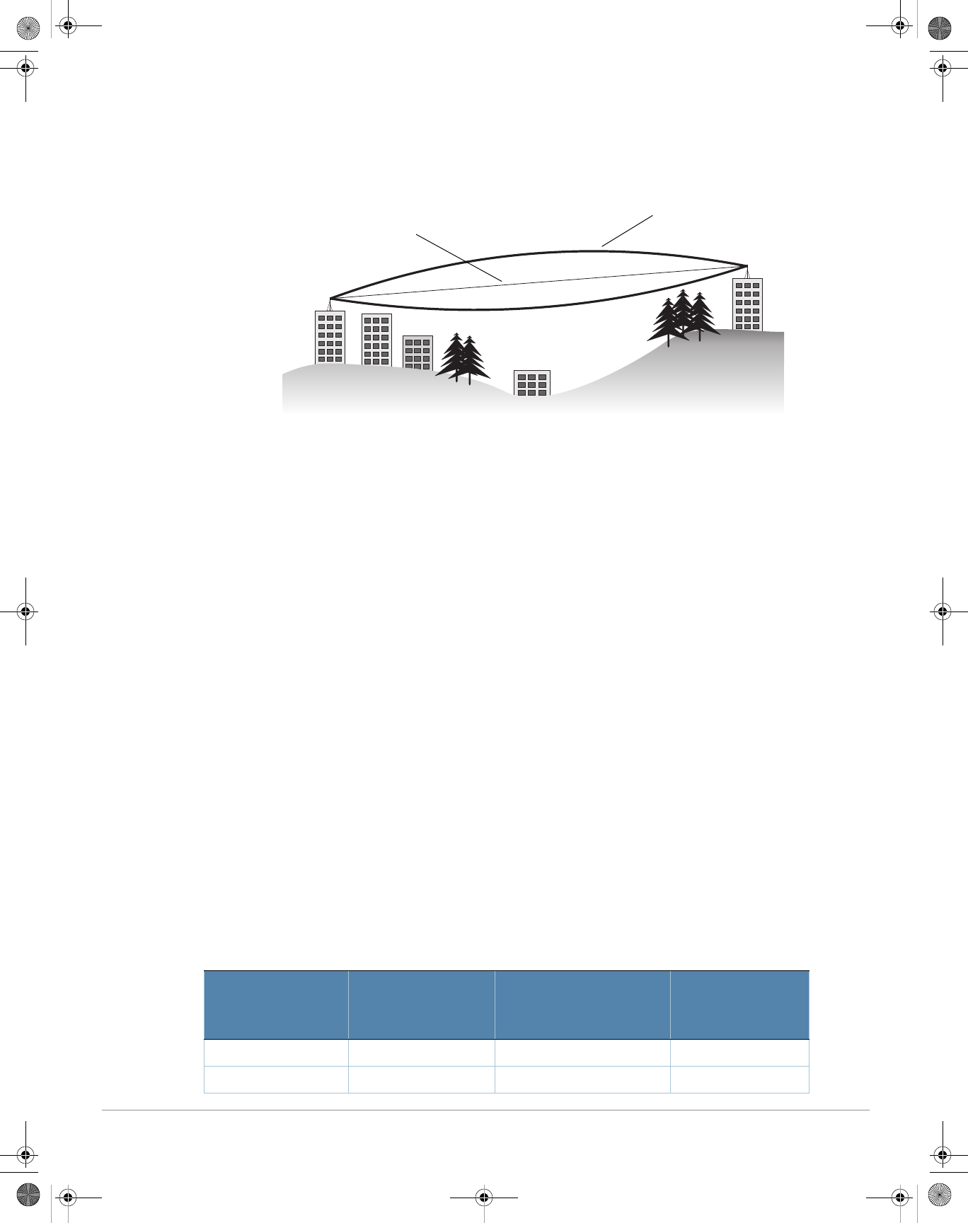
radio signal power travels. This area is known as the first Fresnel Zone of the radio link. For a radio link, no
object (including the ground) must intrude within 60% of the first Fresnel Zone.
Figure 3 illustrates the concept of a good radio line of sight.
Figure 3 Line of Sight
If there are obstacles in the radio path, there may still be a radio link but the quality and strength of the
signal will be affected. Calculating the maximum clearance from objects on a path is important as it directly
affects the decision on antenna placement and height. It is especially critical for long-distance links, where
the radio signal could easily be lost.
When planning the radio path for a wireless bridge or mesh link, consider these factors:
zAvoid any partial line of sight between the antennas
zBe cautious of trees or other foliage that may be near the path, or may grow and obstruct the path.
zBe sure there is enough clearance from buildings and that no building construction may eventually block
the path.
zFor very long distance links, the curvature of the earth (20 cm per km) may need to be considered in the
calculation of relative heights.
zCheck the topology of the land between the antennas using topographical maps, aerial photos, or even
satellite image data (software packages are available that may include this information for your area)
zAvoid a path that may incur temporary blockage due to the movement of cars, trains, or aircraft.
Antenna Height
A reliable wireless bridge or mesh link is usually best achieved by mounting the antennas at each end high
enough for a clear radio line of sight between them. The minimum height required depends on the distance
of the link, obstacles that may be in the path, topology of the terrain, and the curvature of the earth (for
links over 3 miles).
For long-distance links, the AP may have to be mounted on masts or poles that are tall enough to attain the
minimum required clearance. Use the following table to estimate the required minimum clearance above
the ground or path obstruction (for 5 GHz bridge links).
Table 3 Antenna Minimum Height and Clearance Requirements
Total Link Distance
Max Clearance for
60% of First Fresnel
Zone at 5.8 GHz
Approximate Clearance
for Earth Curvature
Total Clearance
Required at
Mid-point of Link
0.25 mile (0.402 km) 4.6 ft (1.4 m) 0.007 ft (0.002 m) 4.6 ft (1.4 m)
0.5 mile (0.805 km) 6.2 ft (1.9 m) 0.03 ft (0.010 m) 6.2 ft (1.9 m)
Radio Line of Sight
Visual Line of Sight
AP-175-IG-Rev01.fm Page 6 Friday, September 17, 2010 4:27 PM
Aruba AP-175 Outdoor Access Point | Installation Guide 7
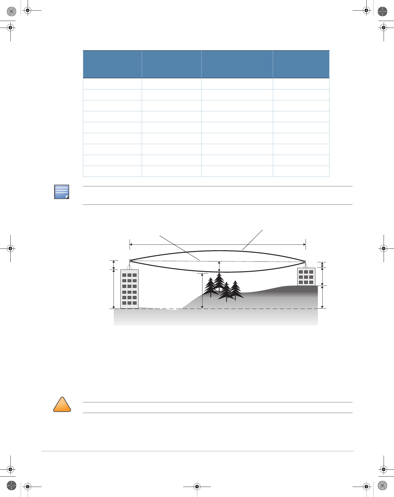
Figure 4 Antenna Height and Line of Sight
A wireless bridge or mesh link is deployed to connect building A to building B, which is located three miles
(4.8 km) away. Mid-way between the two buildings is a small tree-covered hill. From the above table it can
be seen that for a three-mile link, the object clearance required at the mid-point is 5.3 m (17.4 ft). The tree
tops on the hill are at an elevation of 17 m (56 ft), so the antennas at each end of the link need to be at least
22.3 m (73 ft) high. Building A is six stories high, or 20 m (66 ft), so a 2.3 m (7.5 ft) mast or pole must be
constructed on its roof to achieve the required antenna height. Building B is only three stories high, or 9 m
(30 ft), but is located at an elevation that is 12 m (39 ft) higher than building A. To mount an antenna at the
required height on building B, a mast or pole of 1.3 m (4.3 ft) is needed.
1 mile (1.6 km) 8.9 ft (2.7 m) 0.13 ft (0.04 m) 8.9 ft (2.7 m)
2 miles (3.2 km) 12.5 ft (3.8 m) 0.5 ft (0.15 m) 13.1 ft (4.0 m)
3 miles (4.8 km) 15.4 ft (4.7 m) 1.0 ft (0.3 m) 16.4 ft (5.0 m)
4 miles (6.4 km) 17.7 ft (5.4 m) 2.0 ft (0.6 m) 19.7 ft (6.0 m)
5 miles (8 km) 20 ft (6.1 m) 3.0 ft (0.9 m) 23 ft (7.0 m)
7 miles (11.3 km) 23.6 ft (7.2 m) 6.2 ft (1.9 m) 30 ft (9.1 m)
9 miles (14.5 km) 27 ft (8.2 m) 10.2 ft (3.1 m) 37 ft (11.3 m)
12 miles (19.3 km) 30.8 ft (9.4 m) 18.0 ft (5.5 m) 49 ft (14.9 m)
15 miles (24.1 km) 34.4 ft (10.5 m) 28.0 ft (8.5 m) 62.7 ft (19.1 m)
Table 3 Antenna Minimum Height and Clearance Requirements
Total Link Distance
Max Clearance for
60% of First Fresnel
Zone at 5.8 GHz
Approximate Clearance
for Earth Curvature
Total Clearance
Required at
Mid-point of Link
NOTE
To avoid any obstruction along the path, the height of the object must be added to the minimum clearance required
for a clear radio line of sight. Consider the following simple example, illustrated in Figure 4.
AB
3 miles (4.8 km)
5.4 m
17 m
20 m
2.4 m
12 m
9m
1.4 m
Radio Line of Sight
Visual Line of Sight
!
CAUTION
Never construct a radio mast, pole, or tower near overhead power lines.
AP-175-IG-Rev01.fm Page 7 Friday, September 17, 2010 4:27 PM
8Aruba AP-175 Outdoor Access Point | Installation Guide
Antenna Position and Orientation
Once the required antenna height has been determined, other factors affecting the precise position of the
wireless bridge or mesh link must be considered:
zBe sure there are no other radio antennas within 2 m (6 ft) of the wireless bridge or mesh link. These
include other WiFi radio antennas.
zPlace the wireless bridge or mesh link away from power and telephone lines.
zAvoid placing the wireless bridge or mesh link too close to any metallic reflective surfaces, such as roof-
installed air-conditioning equipment, tinted windows, wire fences, or water pipes. Ensure that there is at
least 5 feet clearance from such objects.
zThe wireless bridge or mesh link antennas at both ends of the link must be positioned with the same
polarization direction, either horizontal or vertical. Proper alignment helps to maximize throughput.
Radio Interference
The avoidance of radio interference is an important part of wireless link planning. Interference is caused by
other radio transmissions using the same or an adjacent channel frequency. You should first scan your
proposed site using a spectrum analyzer to determine if there are any strong radio signals using the 802.11a/
b/g channel frequencies. Always use a channel frequency that is furthest away from another signal.
If radio interference is still a problem with your wireless bridge or mesh link, changing the antenna
direction may improve the situation.
Weather Conditions
When planning wireless bridge or mesh links, you must take into account any extreme weather conditions
that are known to affect your location. Consider these factors:
zTemperature: The wireless bridge or mesh link is tested for normal operation in temperatures from
-. Operating in temperatures outside of this range may cause the unit to fail.
zWind Velocity: The wireless bridge or mesh link can operate in winds up to. You must consider the
known maximum wind velocity and direction at the site and be sure that any supporting structure, such
as a pole, mast, or tower, is built to withstand this force.
zLightning: Rain: The wireless bridge or mesh link is weatherproofed against rain. However, it is
recommended to apply weatherproof sealing tape around the Ethernet port and antenna connectors for
extra protection. If moisture enters a connector, it may cause a degradation in performance or even a
complete failure of the link.
zSnow and Ice: Falling snow, like rain, has no significant effect on the radio signal. However, a buildup of
snow or ice on antennas may cause the link to fail. In this case, the snow or ice has to be cleared from
the antennas to restore operation of the link.
NOTE
Local regulations may limit or prevent construction of a high radio mast or tower. If your wireless bridge or mesh link
requires a high radio mast or tower, consult a professional contractor for advice.
!
CAUTION
An Aruba Lightning Arrestor, AP-LAR-1, must be installed on each antenna port for protection against lightning
induced surges. Failure to use an AP-LAR-1 can void the warranty of an Aruba outdoor AP model and renders the
AP susceptible to failure from lightning induced surges
AP-175-IG-Rev01.fm Page 8 Friday, September 17, 2010 4:27 PM

Aruba AP-175 Outdoor Access Point | Installation Guide 9
Ethernet Cabling
When a suitable antenna location has been determined, you must plan a cable route from the wireless
bridge or mesh link outdoors to a suitable power and/or network source.
Consider these points:
zThe Ethernet cable length should never be longer than 90 m (295 ft).
zDetermine a building entry point for the cable (if applicable).
zDetermine if conduits, bracing, or other structures are required for safety or protection of the cable.
zFor lightning protection at the power injector end of the cable, consider using a lightning arrestor
immediately before the cable enters the building
Grounding
It is important that the wireless bridge or mesh link, cables, and any supporting structures are properly
grounded. Each AP-175 access point includes a grounding screw for attaching a ground wire. Be sure that
grounding is available and that it meets local and national electrical codes. Ground the access point first
using the external ground stud on the unit before making any other connection.
Installing the AP-175
The AP-175 can be installed on a wall or attached to a pole. The following section describes how to attach
the necessary hardware to the AP and how to mount the AP in the selected location.
Selecting the Installation Site
zThe site should be located within at least a 60% range of the 1st fresnel zone without obstacles to provide
line of sight (LOS) transmission, increase coverage capacity, and minimize the number of necessary
sites.
zIf no LOS is secured, areas in non-line-of-sight (NLOS) areas could be covered as well, but the distance
of coverage and area of coverage are decreased; more sites are needed to provide coverage for same
area than in the LOS scenario.
zInterference must be considered in site selection. The new site should avoid known interference, unless
the interference is controllable.
zKeep the AP-175 away from places that are susceptible to high temperature, dust, harmful gas,
inflammable, explosive, electromagnetic interference (high power radar, radio station and transformer),
unstable voltage, heavy vibration, or loud noise. In engineering design, the site should be selected
according to the network planning and technical requirements of communications equipment, as well as
the considerations such as climate, hydrology, geology, earthquake, electric power, and transportation.
Installing the AP-175 on a Pole
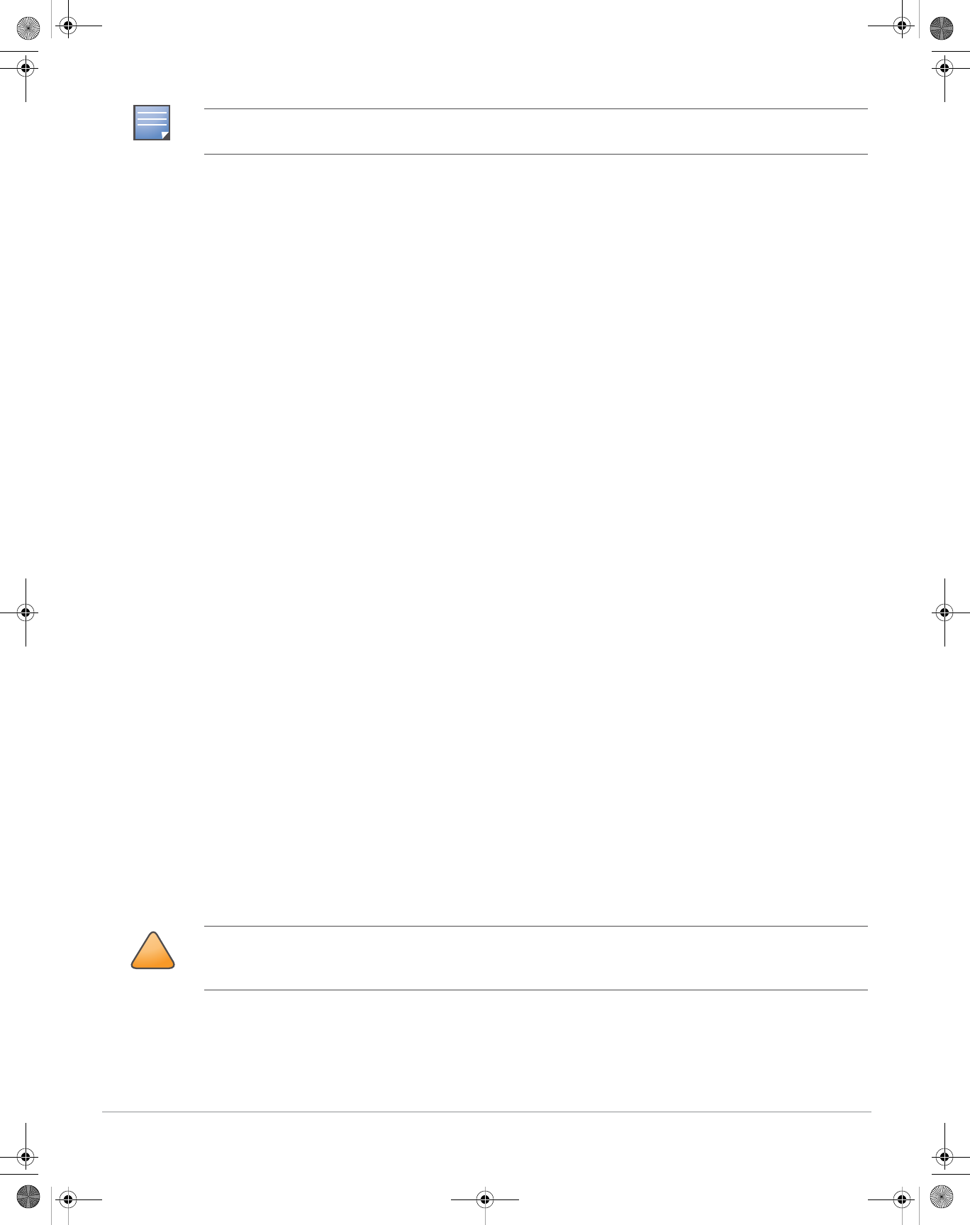
1. Attach the AP-175 on the mounting bracket using the two M6 x30 bolts (with flat and spring washers) on
each side of the mounting bracket.
AP-175-IG-Rev01.fm Page 9 Friday, September 17, 2010 4:27 PM
10 Aruba AP-175 Outdoor Access Point | Installation Guide
Figure 5 Attaching the mounting bracket to the AP
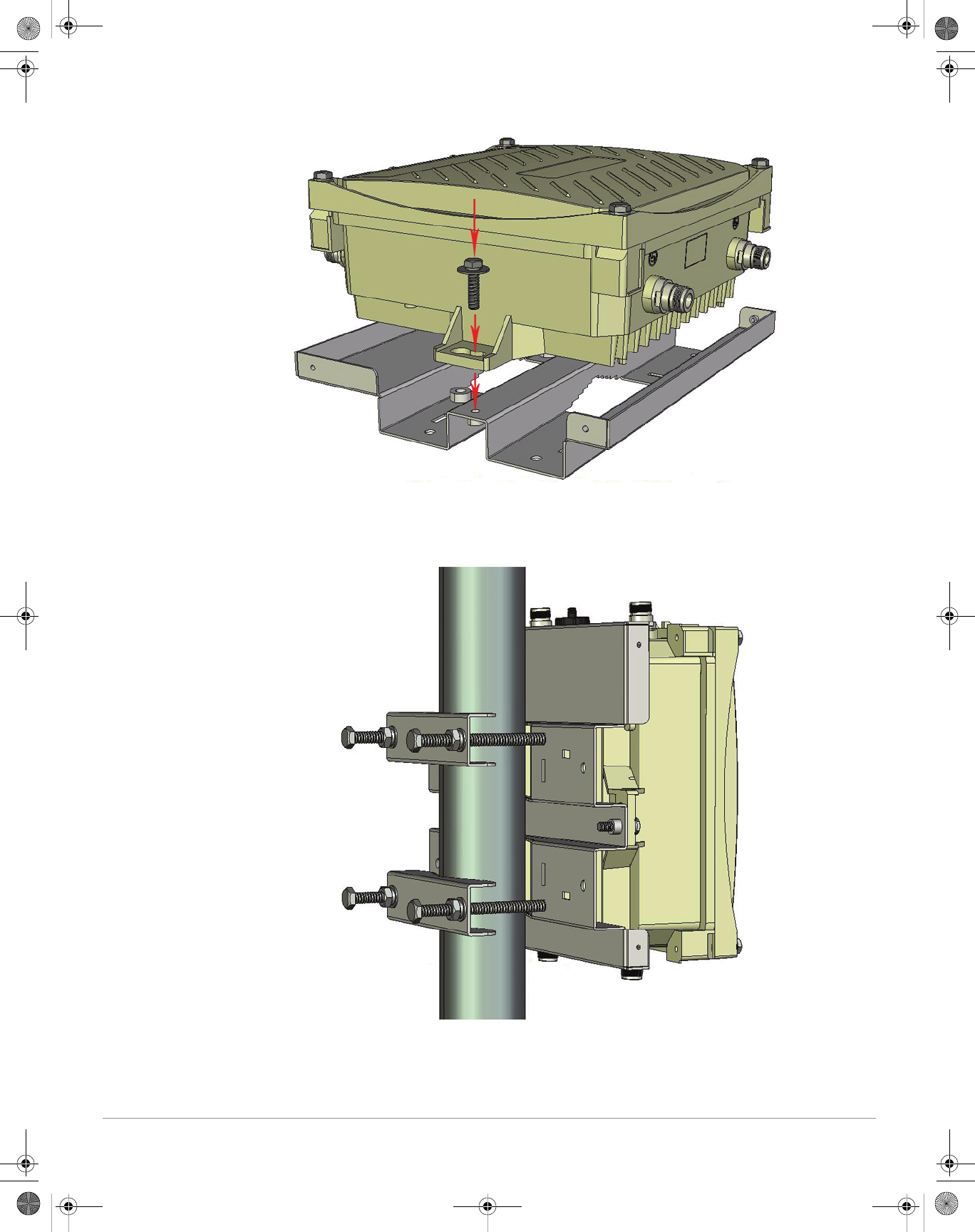
2. Attach the mounting bracket (with AP-175) on the pole using four M8 x110 bolts (with flat washers,
spring washers and nuts) and the pair of pole anchors.
Figure 6 Attaching the mounting bracket to the pole
AP-175-IG-Rev01.fm Page 10 Friday, September 17, 2010 4:27 PM
Aruba AP-175 Outdoor Access Point | Installation Guide 11
Installing the AP-175 on a Wall
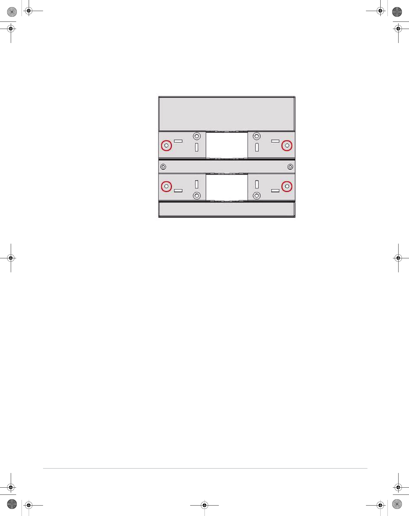
1. Begin by marking the screw points on the wall in the location you have selected.
a. Put the mounting bracket on the installation position against the wall.
b. Mark four expansion screw holes on the wall.
Figure 7 Position of the screw holes
2. Use a drill to create four holes on the four markings you created in the previous step.
3. Install wall (masonry) anchors.
a. Insert a masonry anchor into each drilled hole.
b. Tap the flat end of the anchor with a rubber hammer until the anchor is flush with the wall surface.
4. Attach the mounting bracket to the wall.
a. Align the four holes in the mounting bracket with the anchors and insert four expansion screws
through the installation holes into the anchors.
b. Adjust the position of the mounting bracket and tighten the expansion screws.
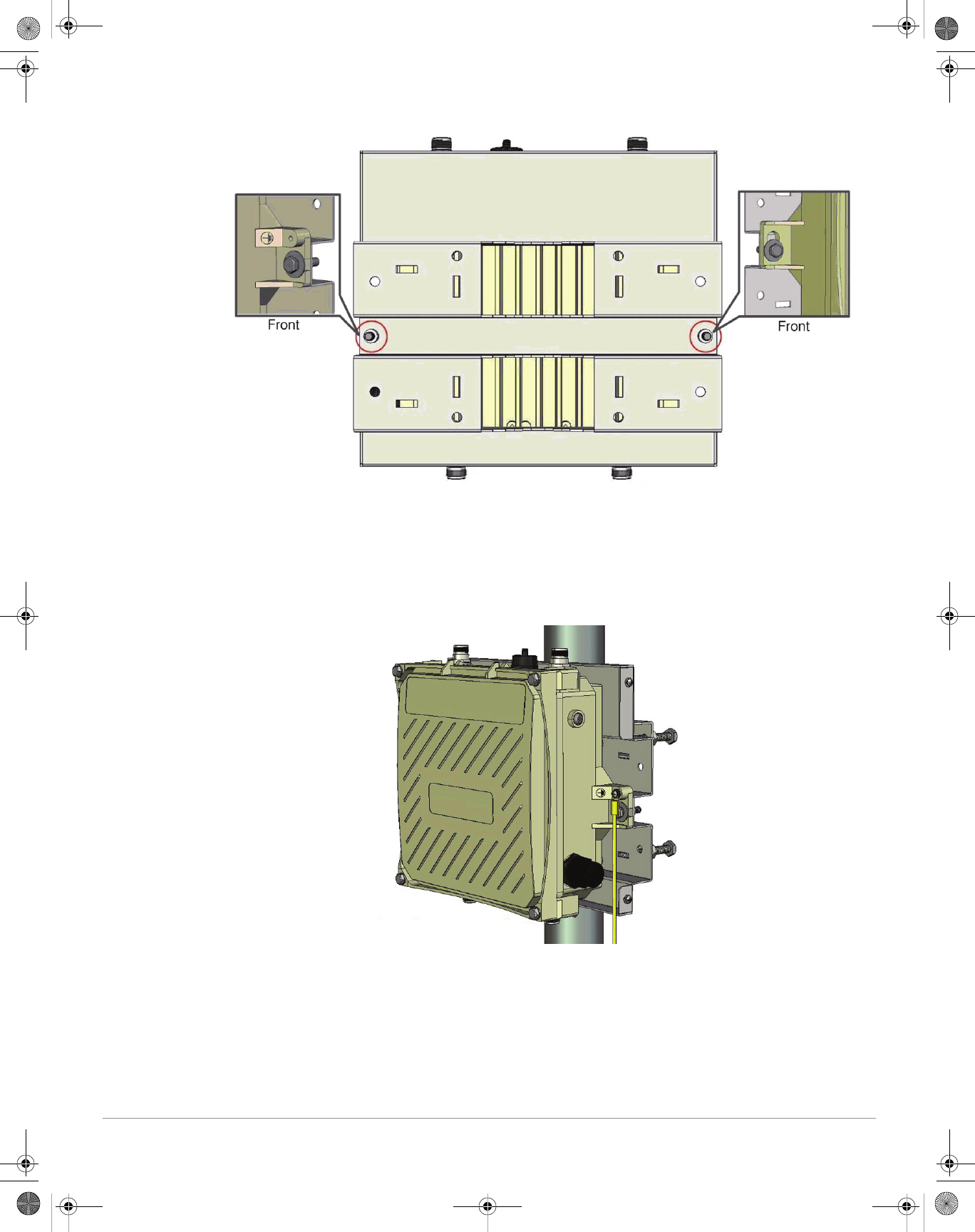
5. Attach the AP-175 to the mounting bracket by inserting the two M6 x30 bolts (with flat and spring
washers) through the installation holes, and tighten the bolts.
AP-175-IG-Rev01.fm Page 11 Friday, September 17, 2010 4:27 PM
12 Aruba AP-175 Outdoor Access Point | Installation Guide
Figure 8 Attaching the AP to the Mounting Bracket
Grounding the AP-175
The grounding must be completed before powering up the AP-175. The resistance of grounding wire should
be less than 5 ohm and the grounding cable’s cross-section area should be no less than 6 mm.The grounding
hole is at the right side of the AP-175.
Figure 9 Grounding the AP-175
1. Peel the cover of one end of the grounding cable (green or yellow and green grounding cable with 6 mm
cross-section area) and place the bare grounding cable into the copper lug, and press firmly with the
crimping pliers.
2. Fasten the copper lug to the grounding hole on the AP-175 with the M4 x12 bolt and external-tooth
washer.
AP-175-IG-Rev01.fm Page 12 Friday, September 17, 2010 4:27 PM
Aruba AP-175 Outdoor Access Point | Installation Guide 13
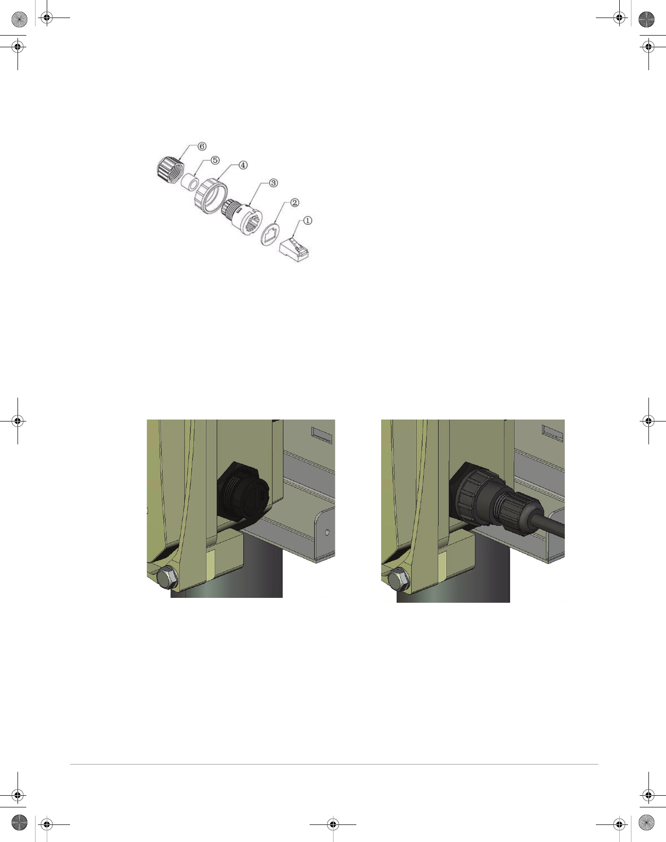
Connecting the Ethernet Cable
1. Remove the protective cap on the Ethernet interface.
2. Attach the waterproof Ethernet connector to the Ethernet cable.
Figure 10 Waterproof Ethernet Connector Cover
3. Insert the ethernet cable connector into the Ethernet interface and hand-tighten the waterproof cover.
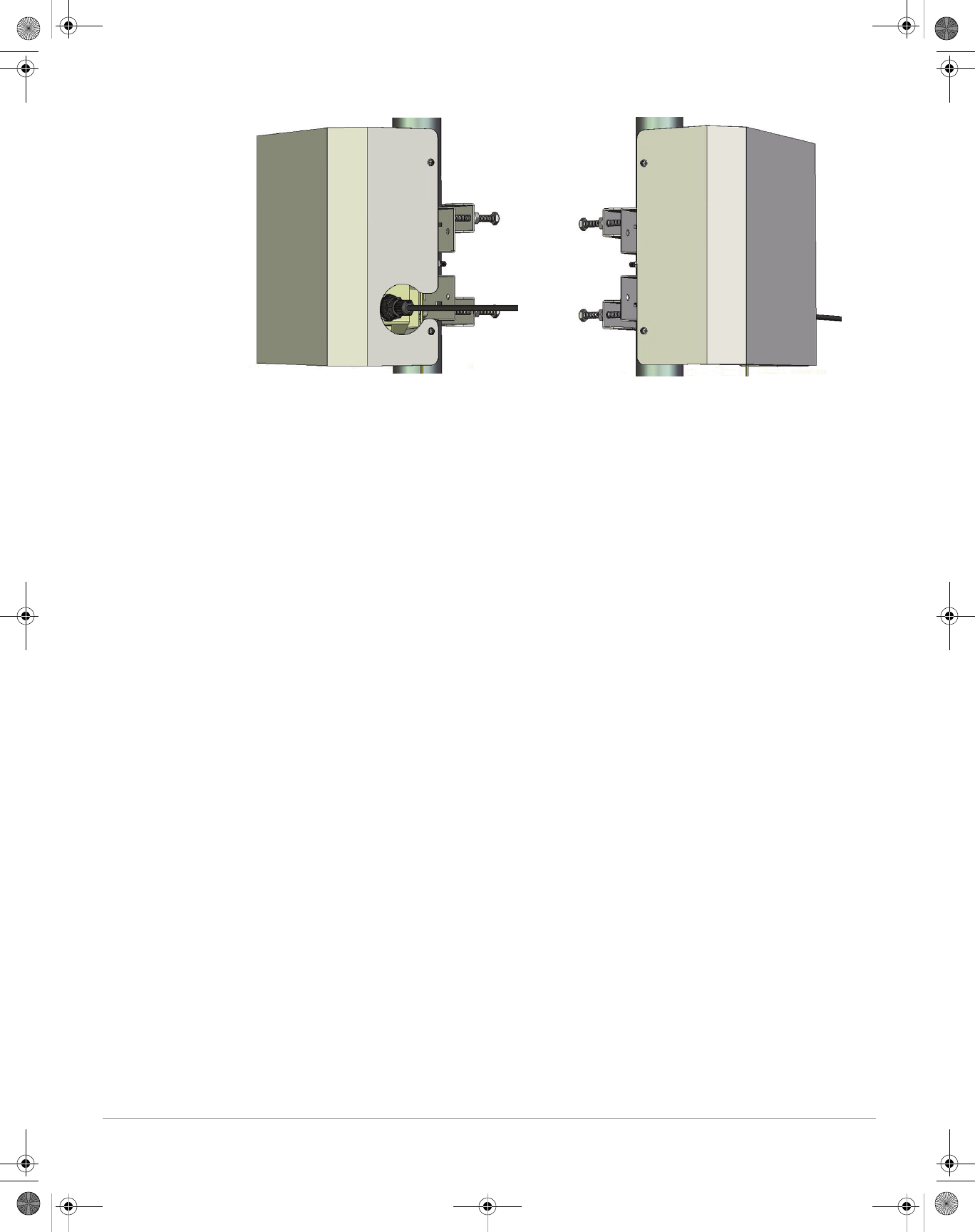
4. Water-proof the Ethernet cable connection with PVC insulation tape, adhesive tape, and a strap.
Figure 11 Connecting the Ethernet cable
Attaching the Solar Shield to the AP-175
Attach the solar shield to the AP-175 by using the four M4 x16 (with flat and spring washers).
1 Shielded RJ45 connector 4 Locknut
2Gasket Mat 5Seal Ring
3 Waterproof Connector Socket 6 Sealing Nut
AP-175-IG-Rev01.fm Page 13 Friday, September 17, 2010 4:27 PM
14 Aruba AP-175 Outdoor Access Point | Installation Guide
Figure 12 Attaching the Solar Shield to the AP
AP-175-IG-Rev01.fm Page 14 Friday, September 17, 2010 4:27 PM
Aruba AP-175 Outdoor Access Point | Installation Guide 15
Safety and Regulatory Compliance
Aruba Networks provides a multi-language document that contains country-specific restrictions and
additional safety and regulatory information for all Aruba access points. This document can be viewed or
downloaded from the following location: www.arubanetworks.com/safety_addendum
FCC Class B Device
This equipment has been tested and found to comply with the limits for a Class B digital device, pursuant to
part 15 of the FCC Rules. These limits are designed to provide reasonable protection against harmful
interference in a residential installation. This equipment generates, uses and can radiate radio frequency
energy and, if not installed and used in accordance with the instructions, may cause harmful interference to
radio communications. However, there is no guarantee that interference will not occur in a particular
installation. If this equipment does cause harmful interference to radio or television reception, which can be
determined by turning the equipment off and on, the user is encouraged to try to correct the interference by
one or more of the following measures:
zReorient or relocate the receiving antenna.
zIncrease the separation between the equipment and receiver.
zConnect the equipment into an outlet on a circuit different from that to which the receiver is connected.
zConsult the dealer or an experienced radio/ TV technician for help.
For a complete list of Country Specific Regulations please speak with your Aruba Representative.
Proper Disposal of Aruba Equipment
For the most current information about Global Environmental Compliance and Aruba products, see our
website at www.arubanetworks.com.
Waste of Electrical and Electronic Equipment
Aruba products at end of life are subject to separate collection and treatment in the EU
Member States, Norway, and Switzerland and therefore are marked with the symbol
shown at the left (crossed-out wheelie bin). The treatment applied at end of life of these
products in these countries shall comply with the applicable national laws of countries
implementing Directive 2002/96EC on Waste of Electrical and Electronic Equipment
(WEEE).
!
CAUTION
RF Radiation Exposure Statement: This equipment complies with FCC RF radiation exposure limits. This
equipment should be installed and operated with a minimum distance of 13.78 inches (35 cm) between the radiator
and your body for 2.4 GHz and 5 GHz operations. This transmitter must not be co-located or operating in
conjunction with any other antenna or transmitter. When operated in the 5.15 to 5.25 GHz frequency range, this
device is restricted to indoor use to reduce the potential for harmful interference with co-channel Mobile Satellite
Systems.
!
CAUTION
Aruba Access Points and the AP-LAR-1 lightning arrestor are required to be installed by a professional installer. The
professional installer is responsible for ensuring that grounding is available and it meets applicable local and
national electrical codes.
WARNING
Do not work on an AP and do not connect or disconnect cables during periods of lightning activity.
AP-175-IG-Rev01.fm Page 15 Friday, September 17, 2010 4:27 PM
Professional installation of antennas is required.
16 Aruba AP-175 Outdoor Access Point | Installation Guide
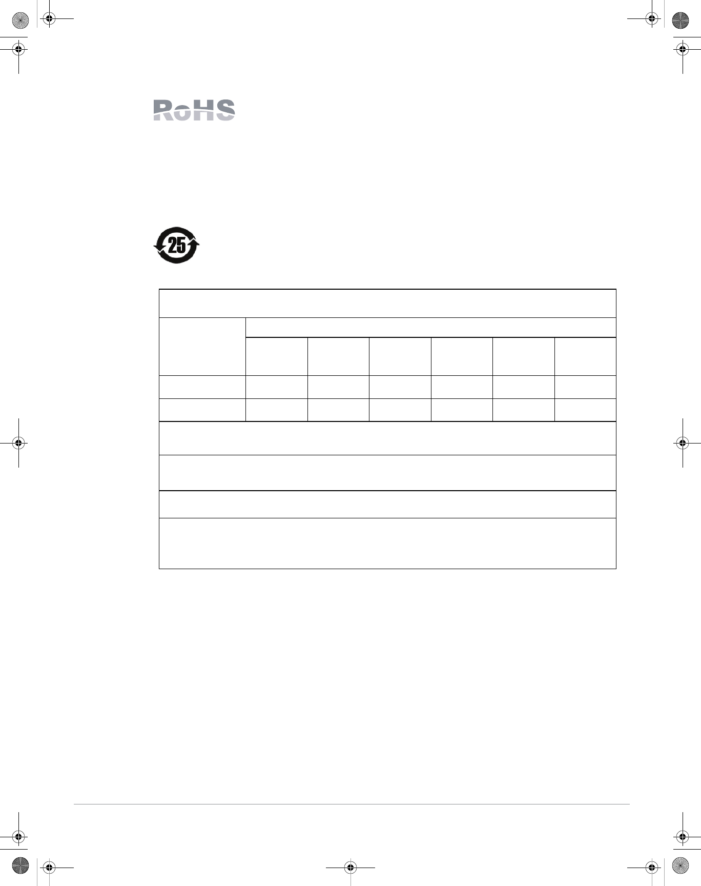
European Union RoHS
Aruba products also comply with the EU Restriction of Hazardous Substances
Directive 2002/95/EC (RoHS). EU RoHS restricts the use of specific hazardous
materials in the manufacture of electrical and electronic equipment. Specifically,
restricted materials under the RoHS Directive are Lead (including Solder used in
printed circuit assemblies), Cadmium, Mercury, Hexavalent Chromium, and Bromine. Some Aruba products
are subject to the exemptions listed in RoHS Directive Annex 7 (Lead in solder used in printed circuit
assemblies). Products and packaging will be marked with the “RoHS” label shown at the left indicating
conformance to this Directive.
China RoHS
Aruba products also comply with China environmental declaration requirements and are
labeled with the “EFUP 25” label shown at the left.
ԫ
ԫԫ
ԫ
˟˸˴˷
˟˸˴˷˟˸˴˷
˟˸˴˷
ʻˣ˵ʼ
ʻˣ˵ʼʻˣ˵ʼ
ʻˣ˵ʼ
ޤ
ޤޤ
ޤ
ˠ˸̅˶̈̅̌
ˠ˸̅˶̈̅̌ˠ˸̅˶̈̅̌
ˠ˸̅˶̈̅̌
ʻ˛˺ʼ
ʻ˛˺ʼʻ˛˺ʼ
ʻ˛˺ʼ
֯
֯֯
֯
˖˴˷̀˼̈̀
˖˴˷̀˼̈̀˖˴˷̀˼̈̀
˖˴˷̀˼̈̀
ʻ˖˷ʼ
ʻ˖˷ʼʻ˖˷ʼ
ʻ˖˷ʼ
ք᪔
ք᪔ք᪔
ք᪔Ւ
ՒՒ
Ւ
˖˻̅̂̀˼̈̀ʳ˩˜
˖˻̅̂̀˼̈̀ʳ˩˜˖˻̅̂̀˼̈̀ʳ˩˜
˖˻̅̂̀˼̈̀ʳ˩˜
˖̂̀̃̂̈́˷̆
˖̂̀̃̂̈́˷̆˖̂̀̃̂̈́˷̆
˖̂̀̃̂̈́˷̆
ʻ˖̅ˉʾʼ
ʻ˖̅ˉʾʼʻ˖̅ˉʾʼ
ʻ˖̅ˉʾʼ
ڍᄽ
ڍᄽڍᄽ
ڍᄽƖʳ
ƖʳƖʳ
Ɩʳ
ˣ̂˿̌˵̅̂̀˼́˴̇˸˷
ˣ̂˿̌˵̅̂̀˼́˴̇˸˷ˣ̂˿̌˵̅̂̀˼́˴̇˸˷
ˣ̂˿̌˵̅̂̀˼́˴̇˸˷
˕˼̃˻˸́̌˿̆
˕˼̃˻˸́̌˿̆˕˼̃˻˸́̌˿̆
˕˼̃˻˸́̌˿̆
ʻˣ˕˕ʼ
ʻˣ˕˕ʼʻˣ˕˕ʼ
ʻˣ˕˕ʼ
ڍᄽʳԲੈ
ڍᄽʳԲੈڍᄽʳԲੈ
ڍᄽʳԲੈ
ˣ̂˿̌˵̅̂̀˼́˴̇˸˷
ˣ̂˿̌˵̅̂̀˼́˴̇˸˷ˣ̂˿̌˵̅̂̀˼́˴̇˸˷
ˣ̂˿̌˵̅̂̀˼́˴̇˸˷
˗˼̃˻˸́̌˿ʳ˘̇˻˸̅
˗˼̃˻˸́̌˿ʳ˘̇˻˸̅˗˼̃˻˸́̌˿ʳ˘̇˻˸̅
˗˼̃˻˸́̌˿ʳ˘̇˻˸̅
ʻˣ˕˗˘ʼ
ʻˣ˕˗˘ʼʻˣ˕˗˘ʼ
ʻˣ˕˗˘ʼ
⚓ʳ
⚓ʳ⚓ʳ
⚓ʳሁࣨ
ሁࣨሁࣨ
ሁࣨ
ˣ˖˔ʳ˕̂˴̅˷
ˣ˖˔ʳ˕̂˴̅˷ˣ˖˔ʳ˕̂˴̅˷
ˣ˖˔ʳ˕̂˴̅˷ ˢ
ˢˢ
ˢˢ
ˢˢ
ˢˢ
ˢˢ
ˢˢ
ˢˢ
ˢˢ
ˢˢ
ˢˢ
ˢˢ
ˢ
ඳ
ඳඳ
ඳýʳ
ýʳýʳ
ýʳٙ
ٙٙ
ٙ
ˠ˸˶˻˴́˼˶˴˿ʳ˦̈˵˴̆̆˸̀˵˿̌
ˠ˸˶˻˴́˼˶˴˿ʳ˦̈˵˴̆̆˸̀˵˿̌ˠ˸˶˻˴́˼˶˴˿ʳ˦̈˵˴̆̆˸̀˵˿̌
ˠ˸˶˻˴́˼˶˴˿ʳ˦̈˵˴̆̆˸̀˵˿̌ ˫
˫˫
˫ˢ
ˢˢ
ˢˢ
ˢˢ
ˢˢ
ˢˢ
ˢˢ
ˢˢ
ˢˢ
ˢˢ
ˢ
ڼ├ݳ←Ӯᆁࢬ௫֗↸ऱ፮অࠌشཚ├ݳˁ
ਬࠄሿຝٙᆨڶԫᄪլٵऱ፮অࠌشཚʻࠏڕʿ⚓ۃցᑓሼʼωڇࠡ↸Ղˁʳڼ፮অࠌشཚૻ⃰شՊ↸ਢڇ↸֫ᅨխࢬˤࡳऱኅٙՀՠ܂ˁ
˧˻˸ʳ˘́̉˼̅̂́̀˸́̇ˀʳ˙̅˼˸́˷˿̌ʳ˨̆˸ʳˣ˸̅˼̂˷ʳʻ˘˙˨ˣʼʳ˹̂̅ʳ˴˿˿ʳ˸́˶˿̂̆˸˷ʳ̃̅̂˷̈˶̇̆ʳ˴́˷ʳ̇˻˸˼̅ʳ̃˴̅̇̆ʳ˴̅˸ʳ̃˸̅ʳ̇˻˸ʳ̆̌̀˵̂˿ʳ̆˻̂̊́ʳ˻˸̅˸ˁʳ˧˻˸ʳ˘́̉˼̅̂́̀˸́̇ˀʳ˙̅˼˸́˷˿̌ʳ˨̆˸ʳˣ˸̅˼̂˷ʳ˼̆ʳ̉˴˿˼˷
̂́˿̌ʳ̊˻˸́ʳ̇˻˸ʳ̃̅̂˷̈˶̇ʳ˼̆ʳ̂̃˸̅˴̇˸˷ʳ̈́˷˸̅ʳ̇˻˸ʳ˶̂́˷˼̇˼̂́̆ʳ˷˸˹˼́˸˷ʳ˼́ʳ̇˻˸ʳ̃̅̂˷̈˶̇ʳ̀˴́̈˴˿ˁ
ڶڶ୭ढᔆࢨցై
ڶڶ୭ढᔆࢨցైڶڶ୭ढᔆࢨցై
ڶڶ୭ढᔆࢨցైʻ
ʻʻ
ʻ˛˴̍˴̅˷̂̈̆ʳ˦̈˵̆̇˴́˶˸̆
˛˴̍˴̅˷̂̈̆ʳ˦̈˵̆̇˴́˶˸̆˛˴̍˴̅˷̂̈̆ʳ˦̈˵̆̇˴́˶˸̆
˛˴̍˴̅˷̂̈̆ʳ˦̈˵̆̇˴́˶˸̆ʼ
ʼʼ
ʼ
ຝٙټ
ຝٙټຝٙټ
ຝٙټᖟ
ᖟᖟ
ᖟ
ʻˣ˴̅̇̆ʼ
ʻˣ˴̅̇̆ʼʻˣ˴̅̇̆ʼ
ʻˣ˴̅̇̆ʼ
ڶڶ୭ढᔆᜢࣔ
ڶڶ୭ढᔆᜢࣔڶڶ୭ढᔆᜢࣔ
ڶڶ୭ढᔆᜢࣔ
˛˴̍˴̅˷̂̈̆ʳˠ˴̇˸̅˼˴˿̆ʳ˗˸˶˿˴̅˴̇˼̂́
˛˴̍˴̅˷̂̈̆ʳˠ˴̇˸̅˼˴˿̆ʳ˗˸˶˿˴̅˴̇˼̂́˛˴̍˴̅˷̂̈̆ʳˠ˴̇˸̅˼˴˿̆ʳ˗˸˶˿˴̅˴̇˼̂́
˛˴̍˴̅˷̂̈̆ʳˠ˴̇˸̅˼˴˿̆ʳ˗˸˶˿˴̅˴̇˼̂́
ˢˍʳʳ।ق͗ʳڶڶ୭ढνʳڇ͗ʳຝٙࢬڶ݁νʳޗறխऱܶၦ݁ڇ˦˝˂˧˄˄ˆˉˆˀ˅˃˃ˉ├ʳˤʳࡳऱૻၦޣאՀΖ
˧˻˼̆ʳ˶̂̀̃̂́˸́̇ʳ˷̂˸̆ʳ́̂̇ʳ˶̂́̇˴˼́ʳ̇˻˼̆ʳ˻˴̍˴̅˷̂̈̆ʳ̆̈˵̆̇˴́˶˸ʳ˴˵̂̉˸ʳ̇˻˸ʳ̀˴̋˼̀̈̀ʳ˶̂́˶˸́̇̅˴̇˼̂́ʳ̉˴˿̈˸̆ʳ˼́ʳ˻̂̀̂˺˸́˸̂̈̆ʳ̀˴̇˸̅˼˴˿̆ʳ̆̃˸˶˼˹˼˸˷ʳ˼́ʳ̇˻˸ʳ˦˝˂˧˄˄ˆˉˆˀ˅˃˃ˉʳ˜́˷̈̆̇̅̌
˦̇˴́˷˴̅˷ˁ
˫ˍʳ।ق͗ʳڶڶ୭ढνʳ۟֟ڇ͗ʳຝٙऱਬԫ݁νʳޗறխऱܶၦ၌נ˦˝˂˧˄˄ˆˉˆˀ˅˃˃ˉ├ʳˤʳࡳऱૻၦޣΖ
˧˻˼̆ʳ˶̂̀̃̂́˸́̇ʳ˷̂˸̆ʳ˶̂́̇˴˼́ʳ̇˻˼̆ʳ˻˴̍˴̅˷̂̈̆ʳ̆̈˵̆̇˴́˶˸ʳ˴˵̂̉˸ʳ̇˻˸ʳ̀˴̋˼̀̈̀ʳ˶̂́˶˸́̇̅˴̇˼̂́ʳ̉˴˿̈˸̆ʳ˼́ʳ˻̂̀̂˺˸́˸̂̈̆ʳ̀˴̇˸̅˼˴˿̆ʳ̆̃˸˶˼˹˼˸˷
˼́ʳ̇˻˸ʳ˦˝˂˧˄˄ˆˉˆˀ˅˃˃ˉʳ˜́˷̈̆̇̅̌ʳ˦̇˴́˷˴̅˷ˁ
ᆁզഇհֲऱࢬഇ↸ʿء।ⓢقʿࠎ␇դऱ⚓ॾஒ↸ױ౨ץܶ᎔ࠄढνΖ
˧˻˼̆ʳ̇˴˵˿˸ʳ̆˻̂̊̆ʳ̊˻˸̅˸ʳ̇˻˸̆˸ʳ̆̈˵̆̇˴́˶˸̆ʳ̀˴̌ʳ˵˸ʳ˹̂̈́˷ʳ˼́ʳ̇˻˸ʳ̆̈̃̃˿̌ʳ˶˻˴˼́ʳ̂˹ʳ˸˿˸˶̇̅̂́˼˶ʳ˼́˹̂̅̀˴̇˼̂́ʳ̃̅̂˷̈˶̇̆ʿʳ˴̆ʳ̂˹ʳ̇˻˸ʳ˷˴̇˸ʳ̂˹ʳ̆˴˿˸ʳ̂˹ʳ̇˻˸ʳ˸́˶˿̂̆˸˷ʳ̃̅̂˷̈˶̇ˁ
AP-175-IG-Rev01.fm Page 16 Friday, September 17, 2010 4:27 PM
Aruba AP-175 Outdoor Access Point | Installation Guide 17
AP-175-IG-Rev01.fm Page 17 Friday, September 17, 2010 4:27 PM

18 Aruba AP-175 Outdoor Access Point | Installation Guide
AP-175-IG-Rev01.fm Page 18 Friday, September 17, 2010 4:27 PM

Aruba AP-175 Outdoor Access Point | Installation Guide 19
AP-175-IG-Rev01.fm Page 19 Friday, September 17, 2010 4:27 PM
Copyright
© 2010 Aruba Networks, Inc. AirWave®, Aruba Networks®, Aruba Mobility Management System®, Bluescanner, For
Wireless That Works®, Mobile Edge Architecture, People Move. Networks Must Follow., RFprotect®, The All
Wireless Workplace Is Now Open For Business, and The Mobile Edge Company® are trademarks of Aruba
Networks, Inc. All rights reserved. All other trademarks are the property of their respective owners.
Open Source Code
Certain Aruba products include Open Source software code developed by third parties, including software code
subject to the GNU General Public License (GPL), GNU Lesser General Public License (LGPL), or other Open Source
Licenses. The Open Source code used can be found at this site:
http://www.arubanetworks.com/open_source
Legal Notice
The use of Aruba Networks, Inc. switching platforms and software, by all individuals or corporations, to terminate
other vendors' VPN client devices constitutes complete acceptance of liability by that individual or corporation for
this action and indemnifies, in full, Aruba Networks, Inc. from any and all legal actions that might be taken against it
with respect to infringement of copyright on behalf of those vendors.
Warranty
This hardware product is protected by the standard Aruba warranty of one year parts/labor. For more information,
refer to the ARUBACARE SERVICE AND SUPPORT TERMS AND CONDITIONS.
Altering this device (such as painting it) voids the warranty.
www.arubanetworks.com
1344 Crossman Avenue
Sunnyvale, California 94089
Phone: 408.227.4500
Fax 408.227.4550
20 Aruba AP-175 Outdoor Access Point | Installation Guide
Contacting Aruba Networks
Web Site Support
Main Site http://www.arubanetworks.com
Support Site https://support.arubanetworks.com
Software Licensing Site https://licensing.arubanetworks.com/login.php
Wireless Security Incident
Response Team (WSIRT) http://www.arubanetworks.com/support/wsirt.php
Support Emails
zAmericas and APAC support@arubanetworks.com
zEMEA emea.support@arubanetworks.com
WSIRT Email
Please email details of any security
problem found in an Aruba product.
wsirt@arubanetworks.com
Telephone Support
Aruba Corporate +1 (408) 227-4500
FAX +1 (408) 227-4550
Support
zUnited States 800-WI-FI-LAN (800-943-4526)
zUniversal Free Phone Service Number
(UIFN): Australia, Canada, China,
France, Germany, Hong Kong, Ireland,
Israel, Japan, Korea, Singapore, South
Africa, Taiwan, and the UK.
+800-4WIFI-LAN (+800-49434-526)
zAll Other Countries +1 (408) 754-1200
AP-175-IG-Rev01.fm Page 20 Friday, September 17, 2010 4:27 PM