Hewlett Packard Enterprise AP2750 Wireless Access Point User Manual KoalaQSG
Hewlett-Packard Company Wireless Access Point KoalaQSG
Users Manual

Quick Start Guide
AP2750 Managed Access Point
3CRWX275075A
The 3Com AP2750 Managed Access Point provides IEEE 802.11a or 802.11b/g wireless access to the
network. The access point is designed for use with a 3Com Wireless LAN Switch, and requires
hardware installation only. All configuration for the access point takes place on the 3Com Wireless
LAN Switch.
You must have a wireless switch device to operate the access point. Two WLAN switch devices can be
connected to the access point:
• 3Com WX4400
• 3Com WX1200
Power can be supplied via Power Over Ethernet (PoE) or by an external power supply. Four 3Com PoE
devices supply power to the access point:
• 3Com PoE Injector
• 3Com 4400PWR PoE Switch
• 3Com Multi-port PoE power supply
• 3Com WX1200
About This Guide
This Quick Start Guide describes the basic installation of the access point. It covers the following topics:
•3Com AP2750 Managed Access Point Features
•Observing Safety Precautions
•Step 1: Unpacking the Access Point
•Step 2: Preparing for Installation
•Step 3: Attaching the Antennas
•Step 4: Mounting the Access Point
•Step 5: Connecting the Access Point to a Switch
•Step 6: Checking the LED Indicators
•Troubleshooting
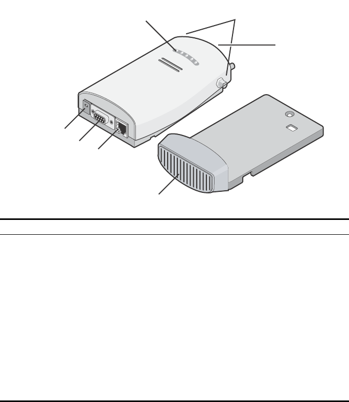
3Com AP2750 Managed Access Point Features
Feature Description
Power Port The access point can be powered either via Power Over Ethernet (PoE), or by an
external power supply (not included) that is plugged into the Power Port.
Serial Port The serial port is not supported.
Ethernet Port The Ethernet port provides a 10/100BASE-TX Ethernet connection to a 3Com Wireless
LAN switch. The connection can be direct to a 3Com switch or indirect through an
intermediate Layer 2 or Layer 3 network.
Use a standard Category 5 cable with straight-through signaling and standard RJ-45
connectors to connect the access point to the switch on the network.
LEDs The LEDs indicate power and activity. See “Checking the LED Indicators” on page 7
for details.
Antenna Connectors Two SMA-female antenna connectors allow you to connect antennas that operate in
2.4 GHz and 5.3 GHz bands.
Reset Button The reset button is accessible from the back of the access point as well as through the
mounting bracket. Push the reset button to restore the access point to its factory
default settings.
Mounting Bracket The mounting bracket comes attached to the access point. This mounting bracket
allows the access point to be mounted to a wall or ceiling.
Power Port
Serial Port
Ethernet Port
Mounting
Bracket
LEDs Antenna
Connectors
Reset
Button

Observing Safety Precautions
This equipment must be installed in compliance with local and national building codes, regulatory
restrictions, and FCC rules. For the safety of people and equipment, only professional network personnel
should install the access point.
1 Unpacking the Access Point
Make sure that you have the following items, which are included with the access point:
• Two external 2.4 GHz and 5.3 GHz dual-band antennas
• Mounting bracket (attached to the access point)
• Wall-mounting hardware:
•Locking bar (used for securing a wall- or ceiling-mounted installation)
•Two sheet metal screws
•Two thread screws
•Two wall anchors
• Four adhesive rubber feet (used for a flat-surface installation).
2 Preparing for Installation
It is advisable to connect the power (if using an external power supply) and check the Ethernet cables
and LEDs before installing the access point in a hard-to-reach location. Additionally, observe the
following items before mounting or connecting the access point:
WARNING: To comply with FCC radio frequency (RF) exposure limits, a minimum body-to-
antenna distance of 20 cm (8 in.) must be maintained when the access point is operational.
WARNING: To avoid possible injury or damage to equipment, you must use power supply equipment
that is safety certified according to UL, CSA, IEC, or other applicable national or international safety
requirements for the country of use. All references to power supply in this document refer to equipment
meeting these requirements.
Installation Item Description
Switch port 3Com recommends that you install and configure the 3Com Wireless LAN switch
before installing the access point. Set the port type on the switch to an AP2750
access point.
Cabling Make sure that standard Category 5 cable with straight-through signaling is
installed at the site before you install the access point.
Make sure that the cable is highly flexible and that there is no extra covering on the
RJ-45 connector that could prevent the cable from being routed through the
mounting bracket.
Power Requirements Power can be supplied via an 802.3af Power Over Ethernet (PoE)-compliant device
or by an external power supply with a minimum 5v @ 2.0 amp.
If using an external power supply, make sure the power outlet is accessible. The
power supply plug is the only means of disconnecting the access point from power.
MAC Address Record the access point MAC address in a safe place before the access point is
installed in a hard-to-reach location.
The MAC address is printed on the back of the access point. Additional MAC
address labels are shipped with the access point.

3 Attaching the Antennas
Carefully unpack the standard detachable antennas. Screw the antennas on to the antenna connectors
on the access point and hand-tighten them. After network startup, you may need to adjust the antennas
to fine-tune coverage in your area.
For best results, adjust the antennas so that they are perpendicular with the floor and ceiling.
4 Mounting the Access Point
The access point can be mounted on the following types of surfaces:
• Wall, ceiling, or electrical box (NEMA enclosure)
•Tabletop
.
Wall, Ceiling, or Electrical Box Mounting
To mount the access point to a wall, ceiling, or electrical box:
1Remove the access point from the mounting bracket.
2Screw the mounting bracket to a wall, ceiling, or electrical box (NEMA enclosure):
•If mounting to a solid surface wall or ceiling, use the two sheet metal screws.
•If mounting to drywall, use the two sheet metal screws and two wall anchors.
•If mounting to an electrical box (NEMA enclosure), use the two threaded screws.
3Route the power cable (if using an external power supply) and Ethernet cable
through the large opening on the back of the mounting bracket.
.
CAUTION: Do not handle the antenna tips, especially after they are connected to the access
point. This could lead to electrostatic discharge (ESD), which could damage the equipment.
CAUTION: The access point is intended for indoor use only. Do not install the access point
outdoors unless you install it in a properly installed outdoor access point enclosure.
CAUTION: For easy installation and removal of the access point from the mounting
bracket, make sure that there is sufficient flexibility with the cable and that there is
adequate service loop (that is, enough cable routed through the mounting bracket
to easily connect the cable to the access point.) If not enough cable is routed
through the back of the mounting bracket, or if the cable is inflexible, it can be
difficult to install or remove the access point from the mounting bracket.
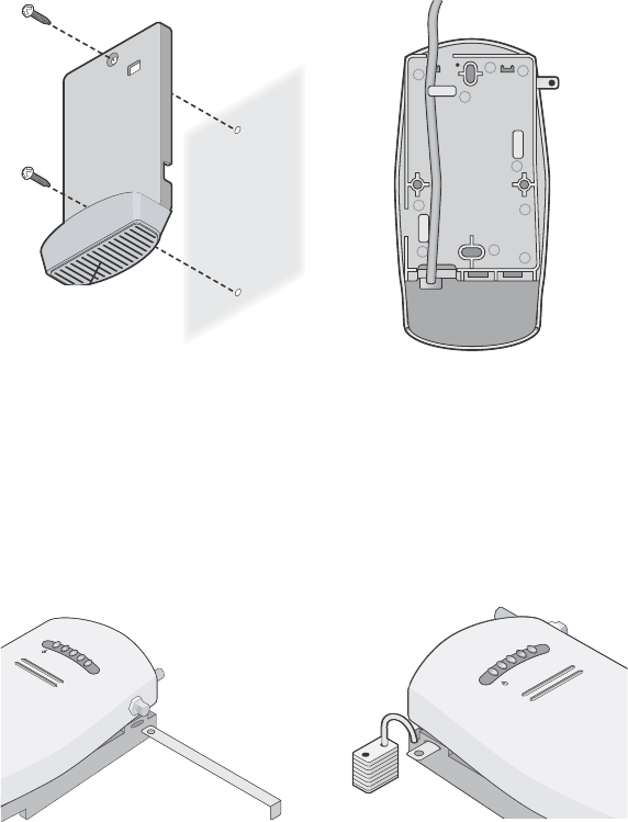
The figures below show the mounting bracket being mounted to a wall, and then a cable
being routed through the large opening on the back of the mounting bracket.
4Connect the Ethernet cable (and power cable, if applicable) to the port(s) on the
front of the access point.
5Snap the access point onto the mounting bracket.
To install the locking bar, push the locking bar through the opening in the side of the
mounting bracket until the hole on the locking bar is exposed. Insert a lock (not provided)
through the hole on the locking bar, and then close the lock to secure it in place.
Installing the mounting bracket Routing a cable
C
r
a
dl
e
Inserting the locking bar Securing the bar with a lock
.11g
.100
.10
.11a
.11g
.100
.10
.11a

Tabletop Mounting
To install the access point on a flat surface such as a table or desktop:
1Remove the backing from the four rubber feet and attach them on the bottom of
the mounting bracket that is attached to the access point.
2Place the access point on the table.
3Connect the Ethernet cable (and power cable, if applicable) to the port(s) on the
front of the access point.
5 Connecting the Access Point to a Switch
3Com recommends that you install and configure the 3Com Wireless LAN switch before installing the
access point. If the switch is already installed and configured for the access point, you can immediately
verify the cable connection when you plug the cable into the access point.
You can connect the access point directly to a 3Com Wireless LAN Switch port or indirectly to
3Com Wireless LAN switches through an intermediate Layer 2 or Layer 3 network. In either case, use
Category 5 cable with straight-through signaling for each access point connection.
• To connect the access point directly to a 3Com Wireless LAN Switch, configure the switch port
as an AP2750 access point and then insert the cable into the switch and verify the link.
• To connect the access point indirectly to a 3Com Wireless LAN Switch through the network,
configure a Distributed Access Point connection on the switch.
CAUTION: Do not place the access point on any type of metal surface. Select a location that
is clear of obstructions and provides good reception.
WARNING: Do not connect or disconnect cables or otherwise work with the access point
during periods of lightning activity.
Note: For instructions on configuring the access point, see the Mobility System
Configuration Guide or the 3Com Wireless LAN Switch Reference Manual.
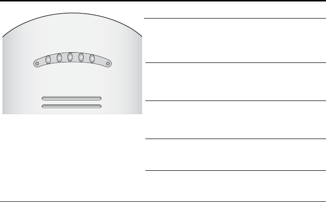
6 Checking the LED Indicators
When the access point is connected to power, LEDs indicate activity as follows (solid LED indicates
connection; blinking LED indicates activity):
Troubleshooting
Refer to the Mobility System Configuration Guide or to the 3Com Wireless LAN Switch Reference
Manual to obtain the access point status.
LED Color Indicates
Power Green
Off
The access point is powered up
and operating normally.
The access point is not receiving
power or there is a fault with the
power supply.
11a Green
Off
The access point has WLAN
frame transmission over the
802.11a 5.3 GHz radio band.
No link is present.
11b/g Green
Off
The access point has WLAN
frame transmission over the
802.11g 2.4 GHz radio band.
No link is present.
100 Green
Off
The access point has a 100 Mbps
Fast Ethernet connection.
No link is present.
10 Green
Off
The access point has a 10 Mbps
Ethernet connection.
No link is present.
11b/g
11a
POWER
100
10

Copyright © 2004 3Com Corporation. All rights reserved. 3Com and the 3Com logo are registered
trademarks of 3Com Corporation. All other company and product names may be trademarks of the
respective companies with which they are associated.
DIA27507-5AAA01
Published October 2004

R
EGULATORY
I
NF
ORMA
TI
ON
The 3Com AP2750 Managed Access Point (3CRWX275075A)
mus
t
be i
n
s
t
alled and
u
s
ed
in
s
trict
acco
rdance
with
th
e man
u
factu
r
er’s
ins
truc
t
ions
as
d
e
s
c
ri
bed i
n
t
h
e us
er d
ocument
a
ti
on
that co
mes
wit
h
th
e
pr
oduc
t. This
d
e
v
i
ce compli
e
s
with
th
e follo
wi
ng radio frequ
enc
y
an
d safety s
t
andards
.
This
prod
uct con
tains
enc
r
ypti
on.
It
is
unlawful to expor
t
ou
t of the U.S.
w
i
tho
u
t obtain
i
ng a
U
.
S.
Expo
rt
Li
cens
e.
This
prod
uct does
no
t cont
ai
n
any
u
s
er se
r
v
iceable
c
ompon
en
ts
. Any
unauthor
ized product chang
es
or
modification
s
will invalid
a
t
e
3C
om’s warranty
and
all applic
a
b
le regulatory cert
ific
atio
ns and
appr
ovals.
This product must be installed by a professional technician/installer.
C
AU
TI
ON
: E
XPOSUR
E
TO
R
ADIO
F
RE
QU
E
N
C
Y
R
ADIA
TI
ON
.
This device generates a
nd radiates
radi
o-frequ
e
n
cy energy.
In or
der to comp
l
y with
F
CC radio-frequency
expo
su
re gu
idelines
f
or
an
uncont
rolled
envir
onment,
th
is
equ
i
pment mus
t
be
in
st
all
e
d
and operated wh
ile
maintain
ing a
minimum body to
antenn
a dis
t
anc
e
of 20 cm (
a
pp
rox
imat
e
l
y
8
in
.)
.
This
device
mus
t
no
t
be c
o
-loc
at
ed
or op
erated i
n
c
onju
nctio
n w
i
th
any
oth
e
r
antenn
a
or
tr
an
smit
ter.
The in
stal
ler
of
thi
s
radio
equipment
mus
t
en
sur
e
that
the ant
e
nn
a is
l
ocated o
r po
inted
s
uch
that
it d
o
es
not
emit RF field in exces
s
of
H
e
alth
C
a
n
a
d
a
limit
s for
th
e general popu
lation;
cons
ult
Safety Cod
e
6,
obtainable
fr
om H
e
alt
h
C
a
n
a
d
a
’
s
w
ebsi
t
e w
ww.
hc-
sc
.g
c.ca
/rpb.
This product must maintain a minimum body to antenna distance of 20 cm. Under these conditions this
product will meet the Basic Restriction limits of 1999/519/EC [Council Recommendation of 12 July 1999
on the limitation of exposure of the general public to electromagnetic fields (0 Hz to 300 GHz)].
USA - R
ADIO
F
RE
QU
E
N
C
Y
R
E
QUI
R
E
ME
NT
S
.
This
device is fo
r
indoor
u
s
e only
w
h
en
u
s
in
g channels
36,
40, 44 or 48
in
th
e 5.
15 to 5.
25 GHz frequ
en
cy
rang
e
.
Hi
gh power r
a
d
a
r
s
are allo
cated as
primary
us
ers
of t
h
e 5.
25 t
o 5.35
GHz and
5.
65 t
o 5.85
GHz b
a
nd
s
.
Thes
e
radar s
t
ations
can caus
e int
e
r
f
eren
ce
w
i
th
and/
or
damage th
is
devi
ce.
USA-F
ED
ERAL
C
OMMU
NI
CATIO
N
S
C
OMMI
SS
ION
(F
CC
)
This
device compl
ies
with
p
a
r
t
15
o
f
the
F
CC Rules
.
Operatio
n
i
s
s
ubject
to
th
e foll
owi
ng two co
nditi
ons
: (
1
)
This device ma
y
no
t cause
harmful
in
te
rference,
and
(
2
)
t
h
is devi
ce mu
st
accept any
int
e
r
f
erence r
e
c
e
i
v
ed,
in
cludi
ng interferenc
e
th
a
t
ma
y caus
e un
desir
e
d
op
er
at
ion.
This
equipment has
b
e
en tes
t
ed
and
fo
und to co
mply wit
h
t
h
e
li
mits
fo
r
a Clas
s B dig
i
tal
d
e
v
i
ce, pu
rsu
a
n
t
to
Part 15 of FC
C Rules. These limit
s are
d
e
sign
e
d
t
o
provide r
e
asonable
prot
e
c
tion
against harmfu
l
in
terference
in
a re
side
n
t
ial
in
s
t
a
l
lation. T
h
is
equip
m
e
n
t
g
e
n
e
r
a
t
e
s
,
u
s
es
, and can radiate
r
a
di
o frequenc
y
energ
y
.
If no
t
in
stalled and used
in
ac
cordanc
e
w
i
th the instruc
t
ions
,
it
may
caus
e h
a
rmf
ul
interferenc
e
to
radio
co
mmunic
a
ti
ons
.
Ho
wever,
th
er
e
is
no
guarantee t
hat in
terference
will
no
t o
ccu
r in
a partic
u
lar installation.
If
th
is equip
m
e
n
t
do
es cause
h
a
rm
f
u
l interferenc
e
to
ra
dio
or
t
e
l
e
v
i
si
on receptio
n, wh
ich can be
d
e
t
e
rm
ined
by
tu
ning
th
e equip
m
en
t
o
ff an
d on,
th
e us
er is enco
uraged to try and correct the interferenc
e by one or
mor
e
of
the followin
g
meas
ures:
■
Reor
ien
t
or relocate the
r
e
c
e
i
v
ing antenn
a
■
Increas
e
the dis
t
a
n
ce be
t
w
ee
n t
h
e equi
pme
n
t
a
n
d t
h
e receive
r
■
Co
nnect the equipment
to
outlet on a
c
i
rcui
t
di
ffere
nt
fro
m th
at
to w
h
ich
th
e
receiver
is
conn
ec
ted
■
Co
ns
ult the deal
er
or
an experie
nced radio
/
TV tec
hnic
i
an
f
o
r help
The user may find th
e foll
owin
g booklet prepared
by the Federal
C
ommuni
cations Commis
s
ion helpful:
The Interference Handb
ook
This
booklet is
available fro
m
th
e U.S. Government
Prin
ting Offi
ce, Wash
ingto
n
, D.
C.
2040
2. Stock No.
004-000-0034504.
3C
om is not
res
pon
sib
l
e
fo
r an
y
r
a
di
o or televis
ion in
terf
er
en
ce
c
a
u
s
ed by un
aut
hori
z
ed
mo
dific
a
t
i
on of the
devi
ces inc
l
uded wit
h
t
h
is
3
C
om
AP2750 Managed Access Point (3CRWX275075A), or the s
ubs
titut
ion or
attachmen
t
o
f
c
onnec
t
ing
cables
and equ
ipment
other
than
s
p
ecifi
e
d
by
3
C
om.
The correc
t
ion of int
e
r
f
erence
c
a
u
s
ed by
s
uch
un
au
t
hor
ized modification,
su
bs
titut
ion or attachment wi
ll be
th
e res
pons
ibi
lity of the us
er.

M
AN
UFA
C
TUR
E
R
’
S
D
ECLA
RATI
ON
OF
C
ONFO
RMIT
Y
3C
om Corp
oration
35
0 C
a
mpus D
r
ive
M
a
rlborough,
MA 017
52-3064,
USA
(
800)
527-8677
Date:
November
8
, 2004
Decl
ar
es
that the Produc
t:
Br
an
d N
a
m
e
: 3
C
om
Cor
poratio
n
M
odel Number: AP2750
Equi
pmen
t Ty
pe: AP2750 Managed Access Point
Complies
w
i
th Par
t
15
o
f
the
F
CC rules
.
Operatio
n
i
s
s
ubject
to
th
e foll
owi
ng two co
nditi
ons
: (
1) thi
s
devic
e
may not caus
e
h
a
r
mful interf
er
en
ce,
and (2
) this
device mus
t
ac
cept
a
n
y interferenc
e
received,
inclu
ding
in
ter
f
erence that may
c
a
us
e undes
i
red operation
.
3Com AP2750 Managed Access Point
Model AP2750

C
ANADA
– I
ND
US
T
R
Y
C
ANADA
(IC)
This
device compl
ies
with
R
S
S 210 of Ind
u
s
try Canada.
Operatio
n
i
s
s
ubject to
th
e foll
owin
g two co
nditio
n
s
:
(
1) thi
s
devic
e
may not caus
e interference, and
(
2
)
th
is
devi
ce
mus
t
accept any int
e
r
f
erence, inc
luding
interferenc
e
that may
caus
e und
es
ired op
er
ati
on of this
devi
ce.”
L ‘
u
t
ilisation de ce
di
s
p
ositif es
t
auto
risé
e s
e
ul
e
m
ent
a
ux co
nditi
ons
suiva
n
tes
:
(1) il ne
do
it pas
pro
duire de
br
ouillage et (2) l’ util
is
ateur
du di
s
positif do
it étr
e
pr
êt à accepter t
out b
roui
llage
radioélectr
i
que
reçu
, même
si
ce br
ouill
ag
e
est
susceptib
l
e de
comp
r
omettre le
f
oncti
onnement du dispo
s
it
if.
The ter
m
"
I
C" before the eq
uipment cert
ification num
ber
only
s
ign
ifies
th
at
th
e
Ind
u
s
try Canada technic
a
l
specifi
c
ations were
met.
To reduc
e p
o
tential radi
o inte
rferenc
e to
other us
ers
,
th
e
antenn
a t
ype an
d its
gain s
houl
d be so c
hos
en that
th
e equiv
a
l
e
n
t
is
ot
ropic
a
ll
y radiated power (
E
I
R
P) is
not more
t
h
an
t
h
at
r
e
quired for
s
ucc
es
s
f
ul
co
mmunicati
on.
To prevent
radi
o
in
terference to the licen
s
ed serv
ice, thi
s
devic
e
is
in
tended to be operated
in
doors
an
d aw
ay
f
r
om wind
ows
to prov
ide
maxi
mum
s
h
ield
ing.
Equ
ipment
(o
r i
t
s
tr
an
smit
antenn
a)
that
is
in
stalled ou
tdoor
s is
s
ubj
ec
t to licens
ing.
Pour
em
p
e
c
h
er qu
e
cet appareil c
a
u
s
e d
u brou
illage au se
rvi
c
e faisa
n
t l'objet
d'u
n
e licenc
e
, il
doit
e
t
re util
ize
a
l'
int
e
ri
eu
r et
devrait
etr
e
place lo
in d
e
s
f
e
n
e
t
r
es
af
in
d
e
Four
nier u
n
ecram d
e
blin
dage maximal. Si le matriel
(
ou s
on antenne
d
'
emis
s
i
on)
es
t ins
t
alle
a l'
ex
terieur, il
do
it
faire l
'
objet d
'
un
e
lic
e
n
ce.
Hi
gh power r
a
d
a
r
s
are allo
cated as
primary
us
ers
of t
h
e 5.
25 t
o 5.35
GHz and
5.
65 t
o 5.85
GHz b
a
nd
s
.
Thes
e
radar s
t
ations
can caus
e int
e
r
f
eren
ce
w
i
th
and/
or
damage th
is
devi
ce.
I
NDU
ST
RY
C
ANADA
(IC)
E
MISSI
ON
S
C
OM
P
L
IA
NC
E
S
TATEMEN
T
This Class
B digit
a
l
apparatu
s
comp
lies wit
h
Canadian ICES-003.
A
VI
S
DE
C
ON
FORM
ITÉ
À
LA
R
É
G
LE
M
E
NTAT
ION
D
’I
ND
US
T
R
IE
C
ANADA
Cet appareil numériq
ue
d
e
la
c
l
ass
e
B
es
t confo
rm à la
no
rme
N
M
B-
003 du Canada.
S
AFE
T
Y
C
OMP
L
IA
NCE
N
OT
ICE
This
device has been tested and certi
fied
ac
cord
i
ng to
the
follo
wing
safety
st
a
n
dards and
is
intend
e
d
fo
r u
s
e
on
ly in Infor
m
at
ion Tec
hnol
ogy Equip
m
ent
w
h
ich
has
been
tes
t
ed to thes
e or oth
e
r
equ
i
valent stan
dards
:
■
UL
Stand
a
rd 60950
(
3rd
Editi
on)
or 60950-1
■
CA
N/
CSA C22.
2 No.
60950
or 60950-1
■
IEC 609
50 or 60950-1
■
EN 60950 or 60950-1

E
UR
O
PE
– EU D
ECLA
RA
TI
ON
OF
C
ON
F
O
RMIT
Y
M
a
rkin
g by the ab
ove
s
y
mb
ol indic
a
t
e
s
compl
ian
c
e
w
i
th the Ess
e
ntial Requir
e
me
nt
s and other relevant
pr
ovision
s
of the R&TTE
D
i
rectiv
e
of the European Un
i
on (1
999/5/E
C
). T
h
is
equip
m
e
n
t
meets
t
h
e
f
o
llowing
co
nfor
man
c
e s
t
andard
s:
EN30
0 328,
EN
301 893
, EN301
489-17
, EN609
50
NOTE: To en
su
re
pr
oduc
t operation
is
in compli
a
n
c
e
w
i
th
loc
a
l regul
at
ions
,
s
elec
t
the
c
ount
ry in whi
ch the
pr
oduc
t i
s
ins
t
alled.
R
e
f
e
r
to the Wireless LAN Mobility System, Wireless LAN Switch and Controller
Configuration G
u
ide.
E
UR
O
PE
- D
ECLA
RATI
ON
OF
C
ONFO
RMIT
Y
IN
L
AN
GUAG
ES
OF
TH
E
E
UROPEA
N
C
OMM
UNI
T
Y
English Hereby, 3Com Corporation, declares that this RLAN device is in
compliance with the essential requirements and other relevant
provisions of Directive 1999/5/EC.
Finnish 3Com Corporation vakuuttaa täten että RLAN device tyyppinen laite
on direktiivin 1999/5/EY oleellisten vaatimusten ja sitä koskevien
direktiivin muiden ehtojen mukainen.
Dutch Hierbij verklaart 3Com Corporation dat het toestel RLAN device in
overeenstemming is met de essentiële eisen en de andere
relevante bepalingen van richtlijn 1999/5/EG
Bij deze verklaart 3Com Corporation dat deze RLAN device voldoet
aan de essentiële eisen en aan de overige relevante bepalingen
van Richtlijn 1999/5/EC.
verklaart 3Com Corporation dat het toestel RLAN device in
overeenstemming is met de essentiële eisen en de andere
relevante bepalingen van richtlijn 1999/5/EG
Bij deze verklaart 3Com Corporation dat deze RLAN device voldoet
aan de essentiële eisen en aan de overige relevante bepalingen
van Richtlijn 1999/5/EC.
French Par la présente 3Com Corporation déclare que l'appareil RLAN
device est conforme aux exigences essentielles et aux autres
dispositions pertinentes de la directive 1999/5/CE
Par la présente, 3Com Corporation déclare que ce RLAN device est
conforme aux exigences essentielles et aux autres dispositions de
la directive 1999/5/CE qui lui sont applicables
Swedish Härmed intygar 3Com Corporation att denna RLAN device står I
överensstämmelse med de väsentliga egenskapskrav och övriga
relevanta bestämmelser som framgår av direktiv 1999/5/EG.
Danish Undertegnede 3Com Corporation erklærer herved, at følgende
udstyr RLAN device overholder de væsentlige krav og øvrige
relevante krav i direktiv 1999/5/EF
German Hiermit erklärt 3Com Corporation, dass sich dieser/diese/dieses
Managed Accces Point in Übereinstimmung mit den grundlegenden
Anforderungen und den anderen relevanten Vorschriften der
Richtlinie 1999/5/EG befindet". (BMWi)
Hiermit erklärt 3Com Corporation die Übereinstimmung des
Gerätes RLAN device mit den grundlegenden Anforderungen und
den anderen relevanten Festlegungen der Richtlinie 1999/5/EG.
(Wien)
Greek ΜΕ ΤΗΝ ΠΑΡΟΥΣΑ 3Com Corporation ∆ΗΛΩΝΕΙ ΟΤΙ RLAN
device ΣΥΜΜΟΡΦΩΝΕΤΑΙ ΠΡΟΣ ΤΙΣ ΟΥΣΙΩ∆ΕΙΣ ΑΠΑΙΤΗΣΕΙΣ
ΚΑΙ ΤΙΣ ΛΟΙΠΕΣ ΣΧΕΤΙΚΕΣ ∆ΙΑΤΑΞΕΙΣ ΤΗΣ Ο∆ΗΓΙΑΣ 1999/5/ΕΚ
Italian Con la presente 3Com Corporation dichiara che questo RLAN
device è conforme ai requisiti essenziali ed alle altre disposizioni
pertinenti stabilite dalla direttiva 1999/5/CE.
Spanish Por medio de la presente 3Com Corporation declara que el RLAN
device cumple con los requisitos esenciales y cualesquiera otras
disposiciones aplicables o exigibles de la Directiva 1999/5/CE

Portuguese 3Com Corporation declara que este RLAN device está conforme
com os requisitos essenciais e outras disposições da Directiva
1999/5/CE.
Malti Hawnhekk, 3Com Corporation, jiddikjara li dan RLAN device
jikkonforma mal-ħtiġijiet essenzjali u ma provvedimenti oħrajn
relevanti li hemm fid-Dirrettiva 1999/5/EC
Estonian Käesolevaga kinnitab 3Com Corporation seadme RLAN device
vastavust direktiivi 1999/5/EÜ põhinõuetele ja nimetatud direktiivist
tulenevatele teistele asjakohastele sätetele.
Hungarian Alulírott, 3Com Corporation nyilatkozom, hogy a RLAN device
megfelel a vonatkozó alapvetõ követelményeknek és az 1999/5/EC
irányelv egyéb elõírásainak.
Slovak 3Com Corporation týmto vyhlasuje, že RLAN device spĺňa základné
požiadavky a všetky príslušné ustanovenia Smernice 1999/5/ES.
Czech 3Com Corporation tímto prohlašuje, že tento RLAN device je ve
shodě se základními požadavky a dalšími příslušnými ustanoveními
směrnice 1999/5/ES.
Slovene Šiuo 3Com Corporation deklaruoja, kad šis RLAN device atitinka
esminius reikalavimus ir kitas 1999/5/EB Direktyvos nuostatas.
Lithuanian Šiuo 3Com Corporation deklaruoja, kad šis RLAN device atitinka
esminius reikalavimus ir kitas 1999/5/EB Direktyvos nuostatas.
Latvian Ar šo 3Com Corporation deklarē, ka RLAN device atbilst Direktīvas
1999/5/EK būtiskajām prasībām un citiem ar to saistītajiem
noteikumiem.
A copy of the signed Declaration of Conformity can be downloaded from the Product Support web page for the
AP2750 (
3CRWX275075A)
at http://www.3com.com.
E
UR
O
PE
–
R
ESTRI
CTION
S
FOR
U
SE
OF
2.4GH
Z
F
R
E
QU
ENCI
ES
IN
E
UROPEA
N
C
OMMU
NITY
C
OU
NT
RI
ES
• This device may be operated indoors or outdoors in all countries of the European Community
using the 2.4GHz band: Channels 1 – 13, except where noted below.
• In Italy the end-user must apply for a license from the national spectrum authority to operate this
device outdoors.
• In Belgium outdoor operation is only permitted using the 2.46 – 2.4835 GHz band: Channel 13.
• In France outdoor operation is only permitted using the 2.4 – 2.454 GHz band: Channels 1 – 7.

E
UR
O
PE
–
R
ESTRI
CTION
S
FOR
U
SE
OF
5GH
Z
F
RE
QU
E
N
C
I
ES
IN
E
UROPEA
N
C
OMMU
NITY
C
OU
NT
RI
ES
Allowed Frequency Bands Allowed Channel Numbers Countries
5.15-5.25GHz 36, 40, 44, 48 Austria
5.15-5.35GHz 36, 40, 44, 48, 52, 56, 60, 64 Belgium, Cyprus, Czech Republic, France,
Hungary, Liechtenstein, Slovakia, Switzerland
5.15-5.35 & 5.470-5.725GHz 36, 40, 44, 48, 52, 56, 60, 64, 100, 104, 108,
112, 116, 120, 124, 128, 132, 136, 140
Bulgaria, Denmark, Estonia, Finland, Germany,
Greece, Iceland, Ireland, Italy, Latvia, Lithuania,
Luxembourg, Malta, Netherlands, Norway, Poland,
Portugal, Slovenia, Spain, Sweden, U.K.
• This device may be not be operated outdoors when using the bands 5150-5350MHz (Channels
36, 40, 44, 48, 52, 56, 50, 64).
• In Italy the end-user must apply for a license from the national spectrum authority to operate this
device outdoors.
•
To
rema
in in
c
onfo
rmance w
i
th
Europea
n
spectr
um
u
s
age laws
fo
r Wireless
LAN
op
er
at
ion,
t
h
e abov
e
•
2.
4GHz and 5GHz
channel
li
mitation
s apply
.
The
us
er sh
ould ch
ec
k th
e cur
rent channel of operati
on.
If
operatio
n
is
occu
rring ou
ts
ide of
th
e allowabl
e frequ
en
cies as lis
ted ab
ove, the us
er
mus
t
ceas
e
op
erating
the
Managed Access Point
at
th
at
lo
ca
tion
and co
nsu
l
t the
l
ocal techni
cal
s
up
port s
t
aff
resp
onsible for
the wir
e
less
netw
ork.
•
The 5GHz Turbo
mod
e
feature is
not allo
wed for op
er
ation in an
y Eu
ropean Commun
i
ty cou
ntry
.
•
This
device mus
t
b
e us
ed with
the
radar detecti
on feat
ure requir
e
d
fo
r Eur
opean
C
o
mmunit
y
op
eration
in
the
5GHz
bands
.
This
device will
avoi
d
operating
on a ch
annel occ
upied b
y
any radar
s
y
s
t
em in the area
.
The
pres
en
ce of n
e
arb
y
radar op
er
at
ion may
res
ul
t
in t
e
mp
orary in
terrup
t
ion
in co
mmun
icati
ons
of t
h
is
device.
T
h
e
Ac
ces
s
P
oint’s
radar detect
ion fea
t
ure will automa
tic
ally res
t
a
r
t
op
eration on
a channel free
o
f
r
a
d
a
r.
You may
c
ons
ult wit
h the
l
ocal technic
a
l
s
upp
ort s
t
aff
respo
n
s
i
ble for the wireles
s
netw
ork
t
o
en
sur
e
th
e
Acc
e
ss
Poi
n
t device(
s
)
ar
e pro
p
erly con
fi
gur
e
d
fo
r E
u
ropean Commun
i
ty operatio
n.