Hewlett Packard Enterprise AP3950 WLAN Managed Access Point User Manual 3Com AP3950 Quick Installation Guide
Hewlett-Packard Company WLAN Managed Access Point 3Com AP3950 Quick Installation Guide
Contents
- 1. user manual
- 2. User Manual
- 3. User manual
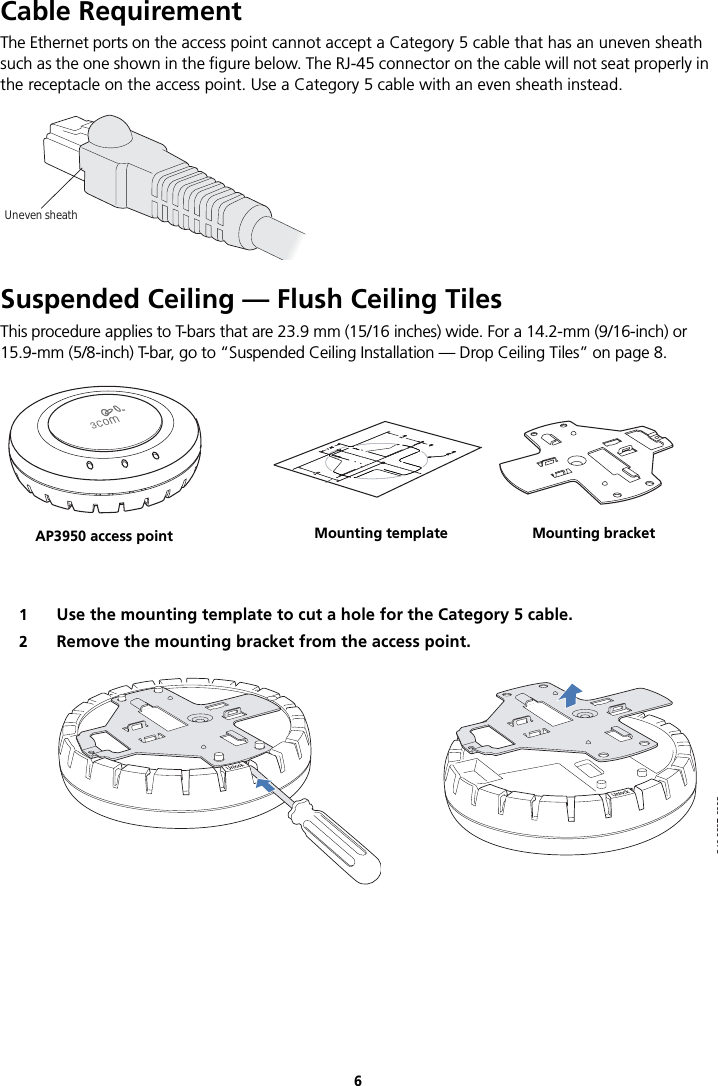
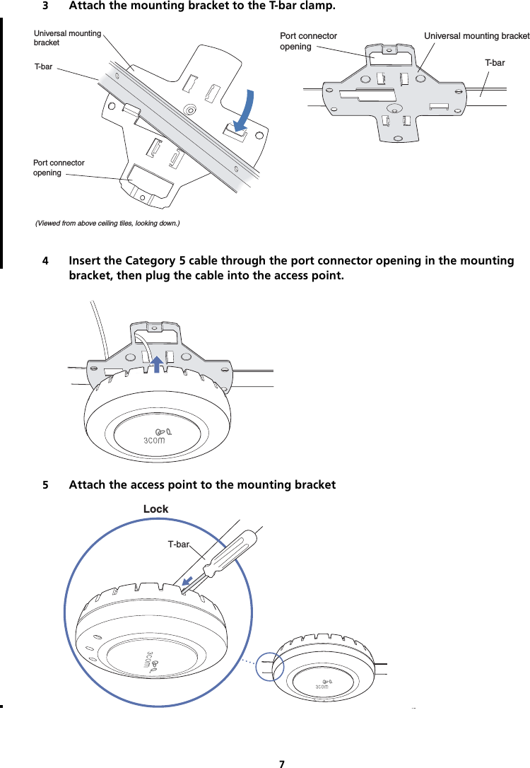
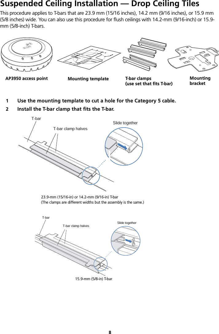
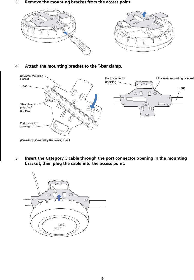
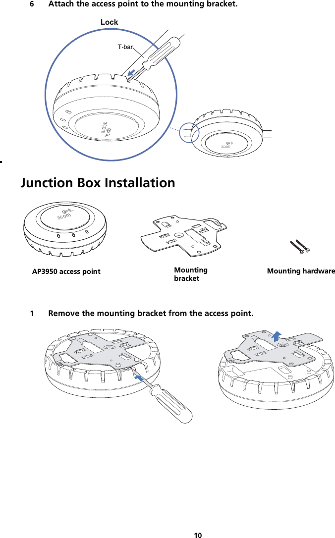
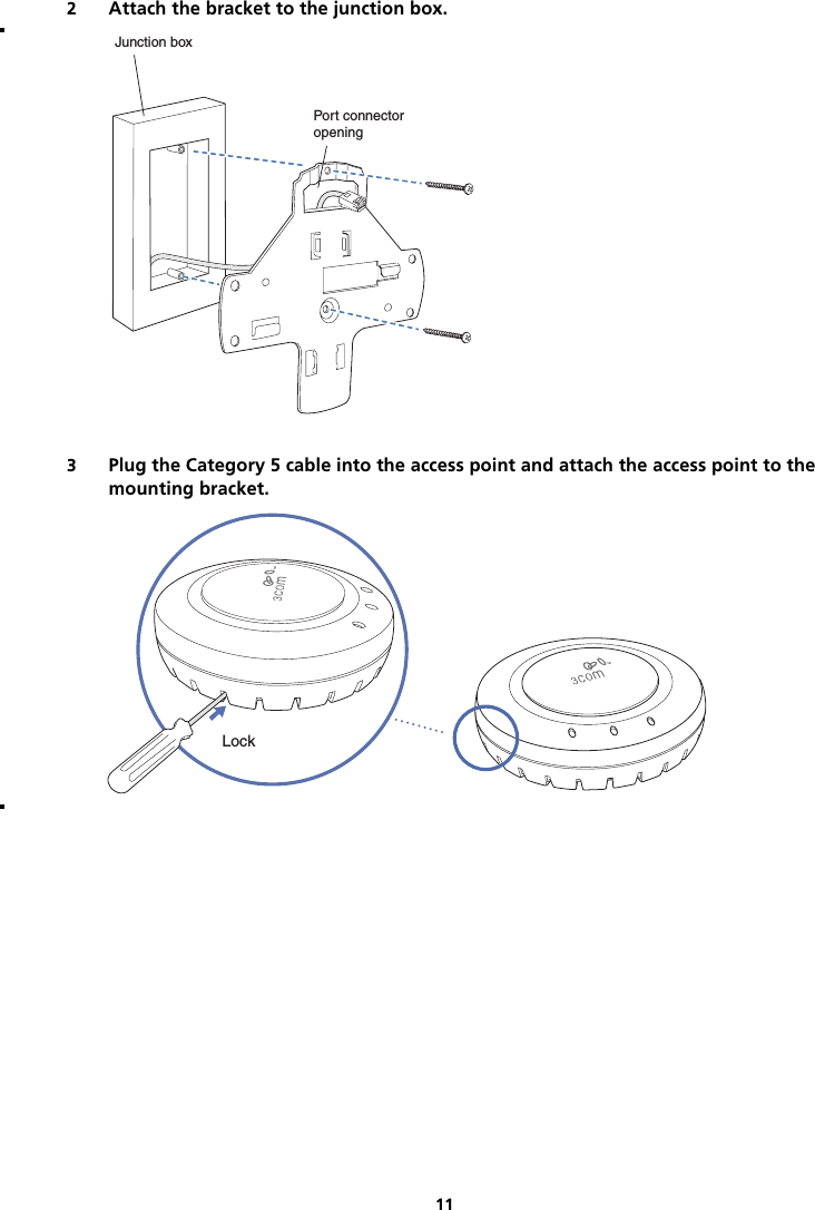
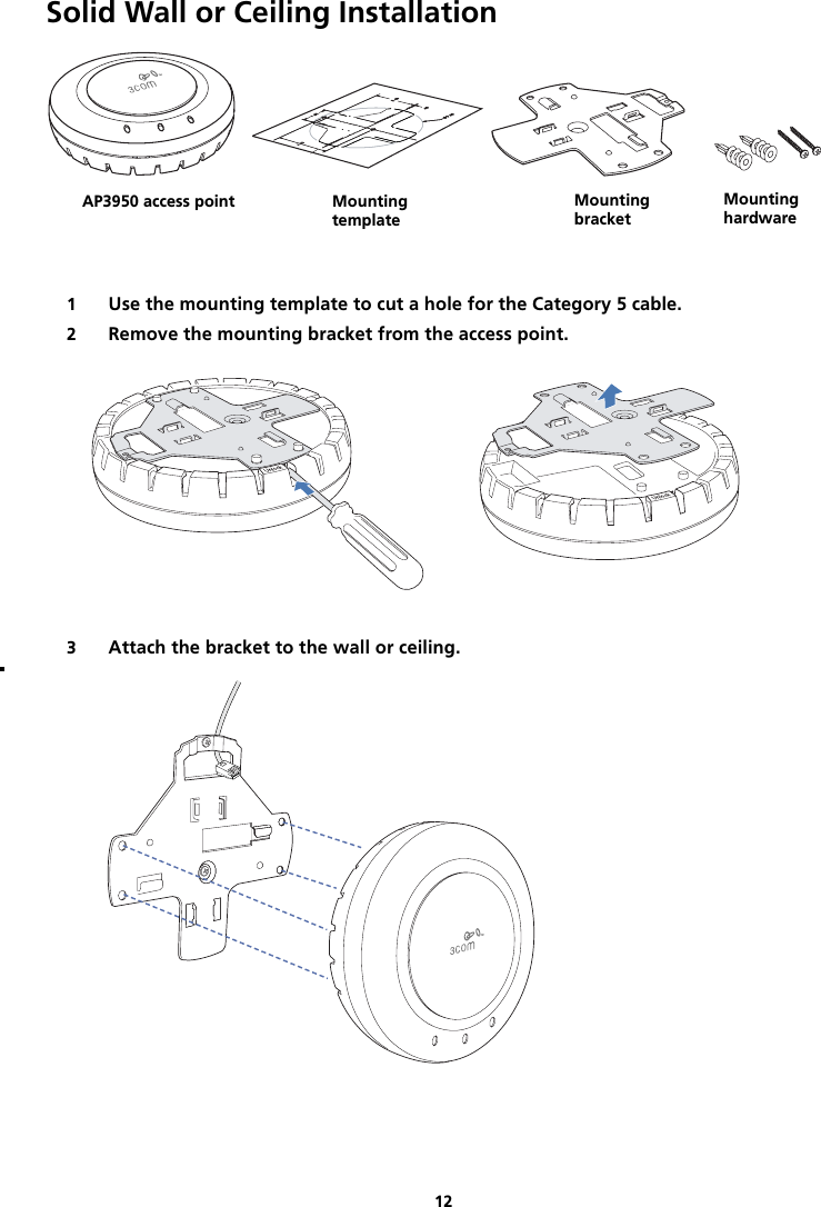
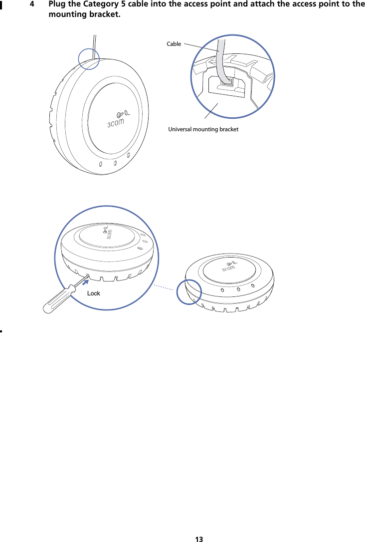
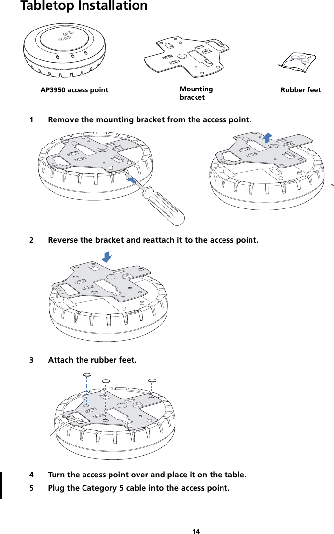
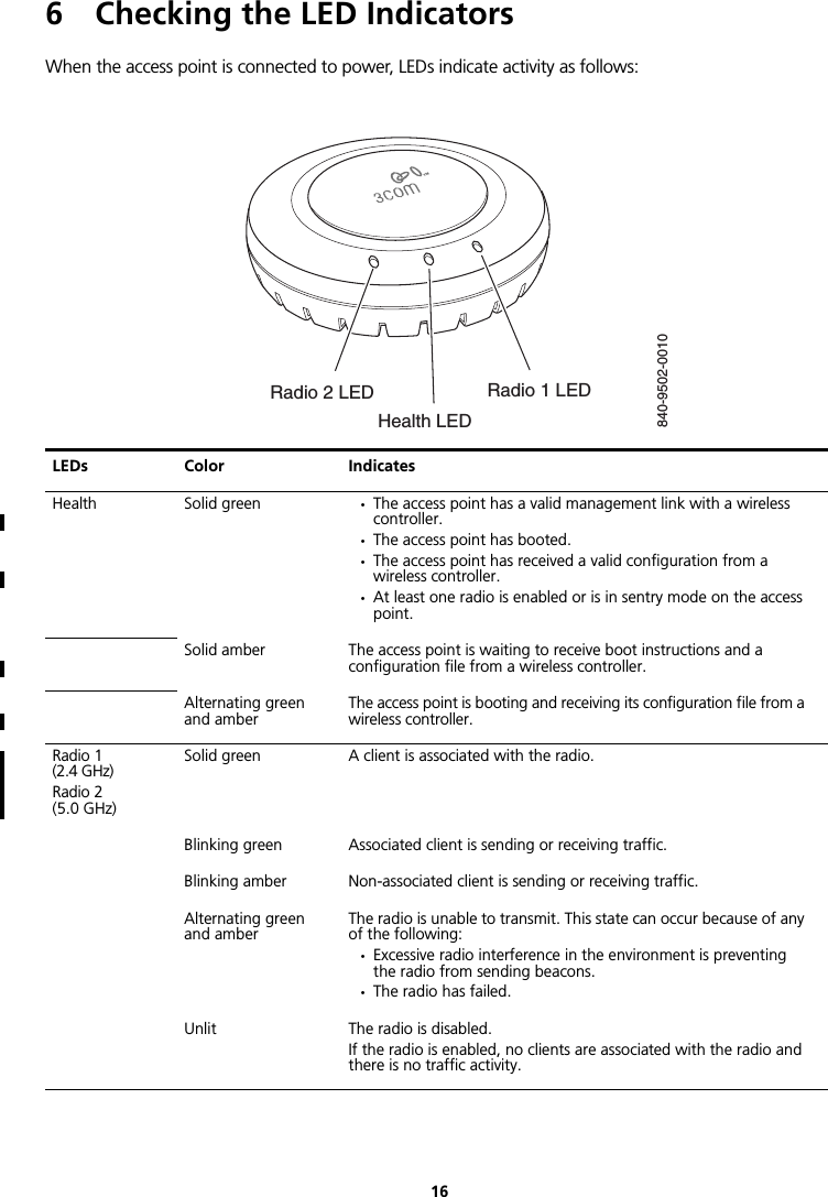
user manual
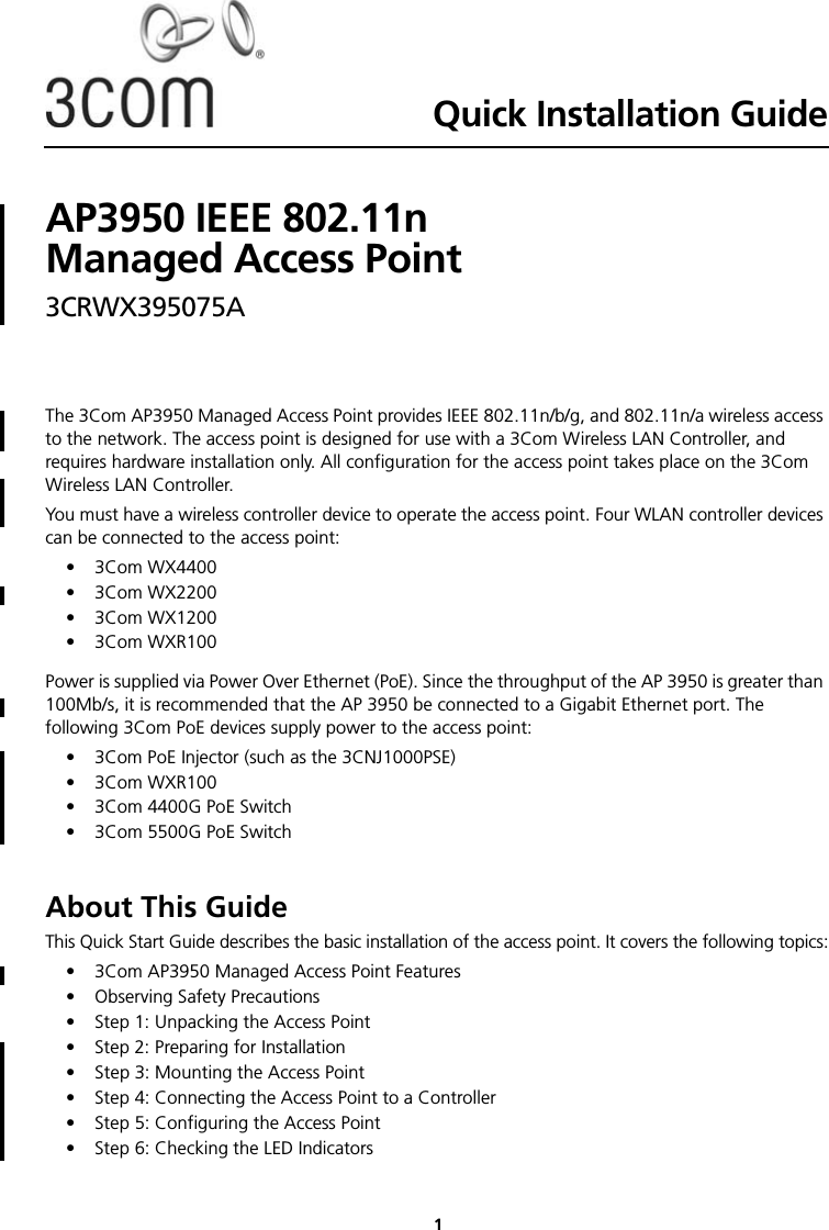
![17Regulatory InformationThe 3Com AP3950 Managed Access Point (3CRWX395075A) must be installed and used in strict accordance with the manufacturer's instructions as described in the user documentation that comes with the product.This product does not contain any user serviceable components. Any unauthorized product changes or modifications will invalidate 3Com's warranty and all applicable regulatory certifications and approvals. This product must be installed by a professional technician/installer.CAUTION: EXPOSURE TO RADIO FREQUENCY RADIATIONThis device generates and radiates radio-frequency energy. In order to comply with FCC radio-frequency exposure guidelines for an uncontrolled environment, this equipment must be installed and operated while maintaining a minimum body-to-antenna distance of 20 cm (approximately 8 in.).The installer of this radio equipment must ensure that the antenna is located or pointed such that it does not emit RF field in excess of Health Canada limits for the general population; consult Safety Code 6, obtainable from Health Canada's website www.hc-sc.gc.ca/rpb.This product must maintain a minimum body-to-antenna distance of 20 cm. Under these conditions this product will meet the Basic Restriction limits of 1999/519/EC [Council Recommendation of 12 July 1999 on the limitation of exposure of the general public to electromagnetic fields (0 Hz to 300 GHz)].USA - RADIO FREQUENCY REQUIREMENTS.This device must not be co-located or operated in conjunction with any other antenna or transmitter.This device is for indoor use only when using channels 36, 40, 44 or 48 in the 5.15 to 5.25 GHz frequency range.High power radars are allocated as primary users of the 5.25 to 5.35 GHz and 5.65 to 5.85 GHz bands. These radar stations can cause interference with and/or damage this device.USA-FEDERAL COMMUNICATIONS COMMISSION (FCC) EMC ComplianceThis equipment has been tested and found to comply with the limits for a Class B digital device, pursuant to Part 15 of FCC Rules. These limits are designed to provide reasonable protection against harmful interference in a residential installation. This equipment generates, uses, and can radiate radio frequency energy. If not installed and used in accordance with the instructions, it may cause harmful interference to radio communications. However, there is no guarantee that interference will not occur in a particular installation. If this equipment does cause harmful interference to radio or television reception, which can be determined by tuning the equipment off and on, the user is encouraged to try and correct the interference by one or more of the following measures:• Reorient or relocate the receiving antenna• Increase the distance between the equipment and the receiver• Connect the equipment to outlet on a circuit different from that to which the receiver is connected• Consult the dealer or an experienced radio/TV technician for helpThe user may find the following booklet prepared by the Federal Communications Commission helpful:The Interference HandbookThis booklet is available from the U.S. Government Printing Office, Washington, D.C. 20402. Stock No. 004-000-0034504.3Com is not responsible for any radio or television interference caused by unauthorized modification of the devices included with this 3Com AP3950 Managed Access Point (3CRWX395075A), or the substitution or attachment of connecting cables and equipment other than specified by 3Com.The correction of interference caused by such unauthorized modification, substitution or attachment will be the responsibility of the user.Changes or modifications not expressly approved by 3Com could void the user’s authority to operate this equipment.Note: This product contains encryption. It is unlawful to export out of the U.S. without obtaining a U.S. Export License.](https://usermanual.wiki/Hewlett-Packard-Enterprise/AP3950.user-manual/User-Guide-962355-Page-19.png)