Hewlett Packard Enterprise AP6061SDR AP 60 and AP 61 Single-Radio Wireless Access Point User Manual
Aruba Networks, Inc. AP 60 and AP 61 Single-Radio Wireless Access Point
Contents
- 1. User Manual
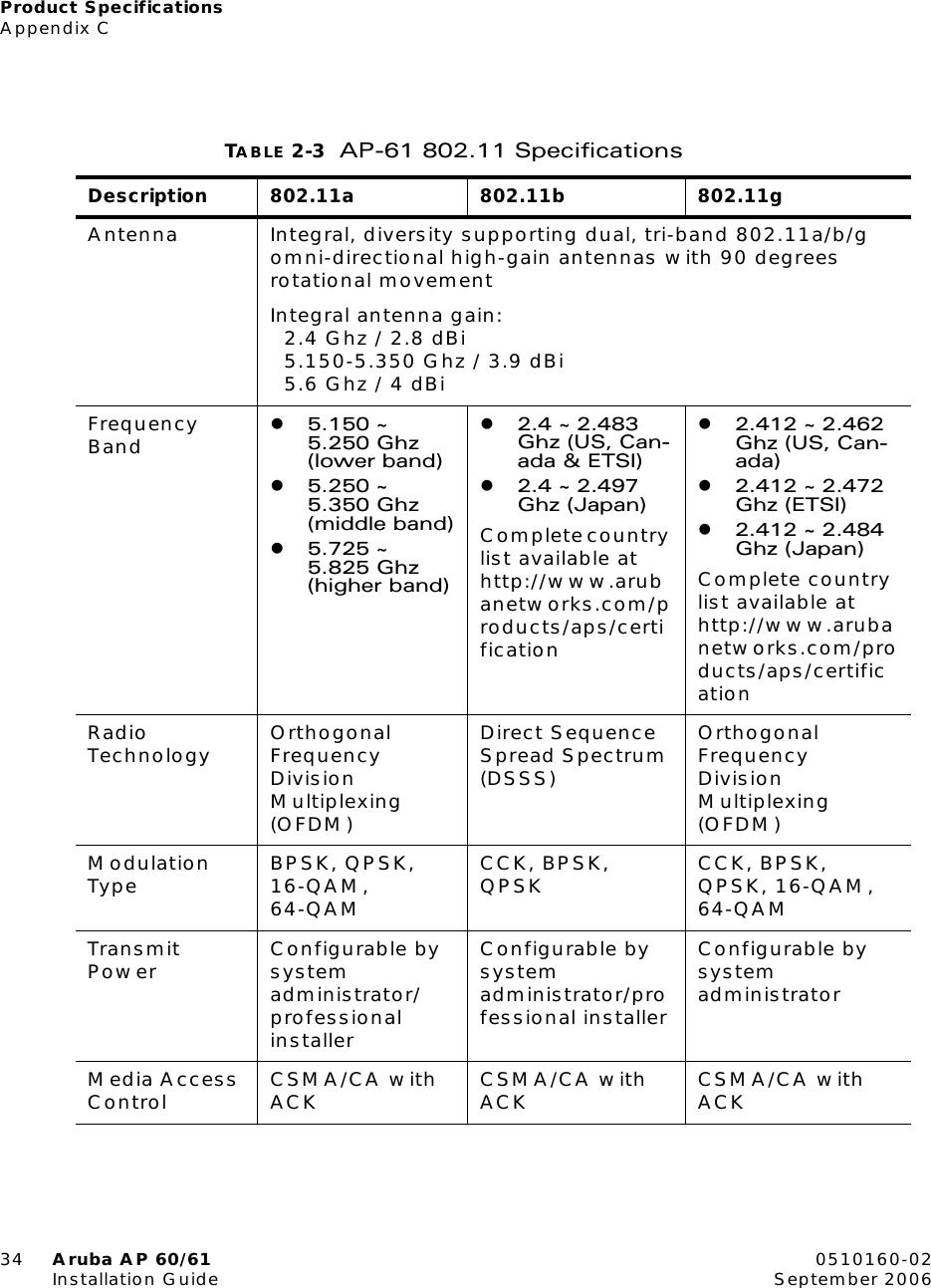
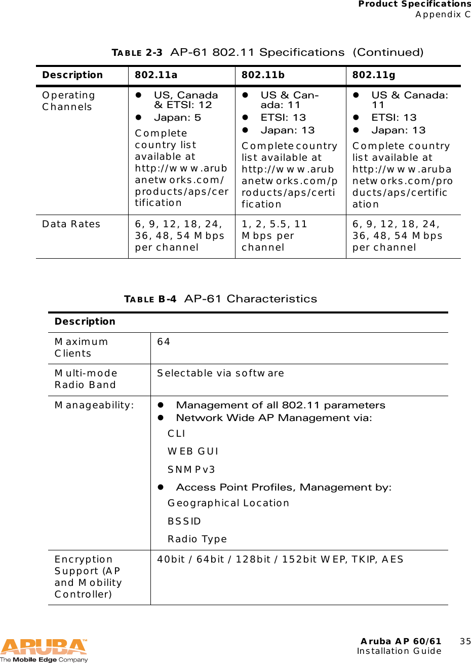
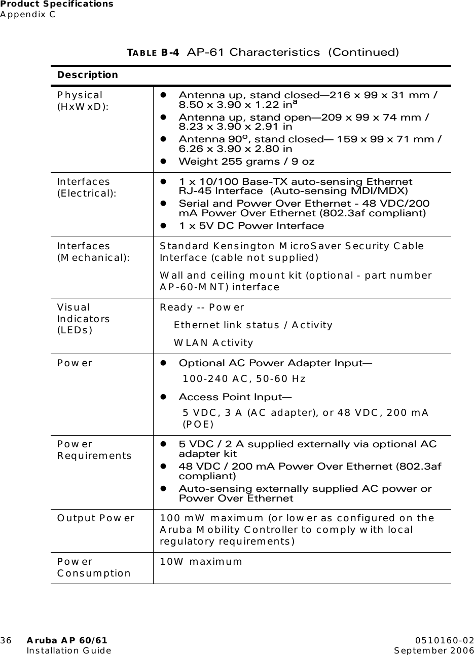
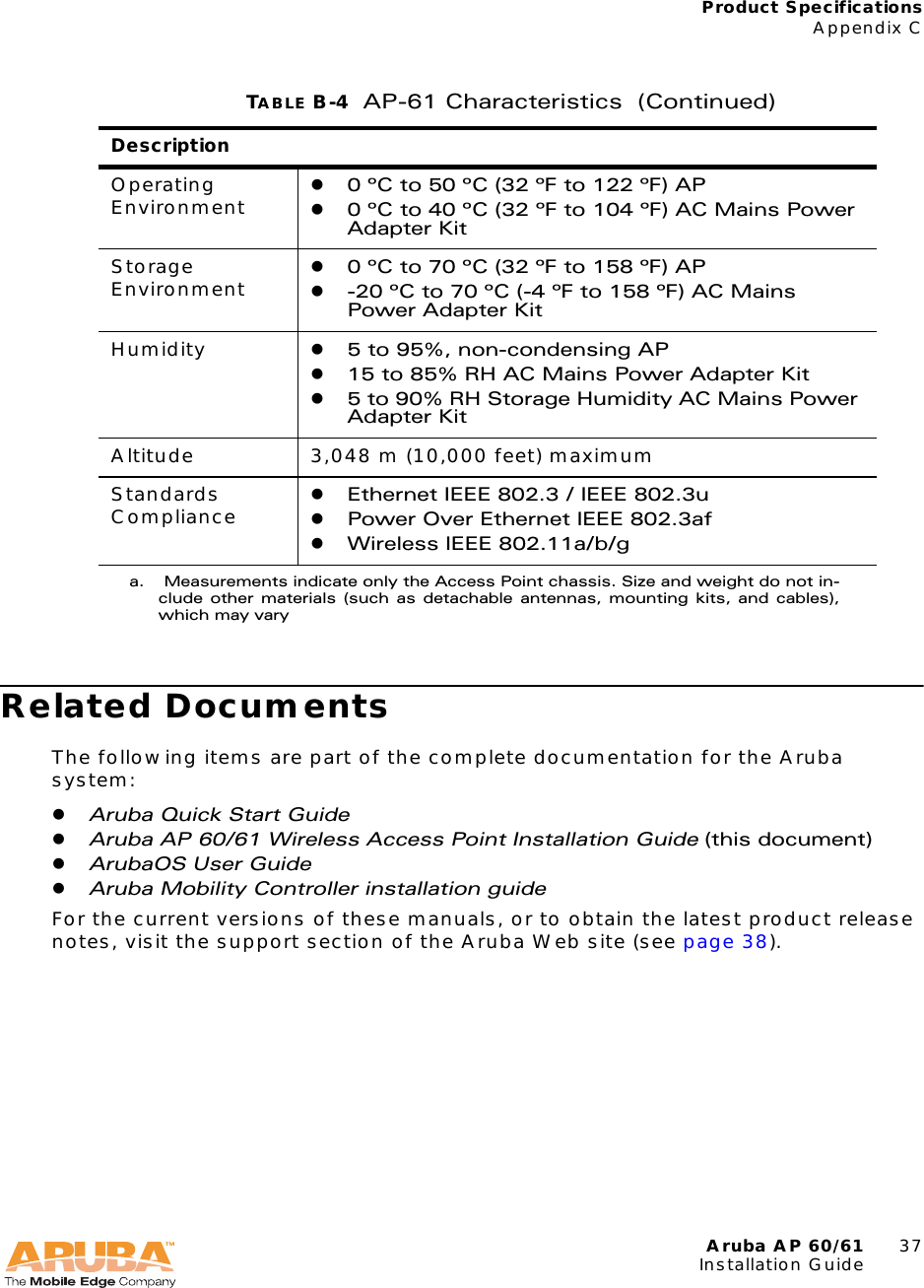
- 2. Technical Product Description
- 3. Users Manual
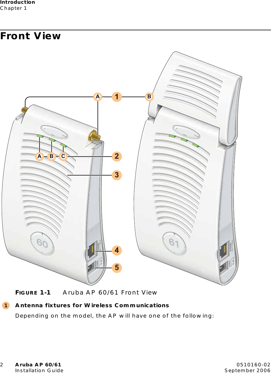
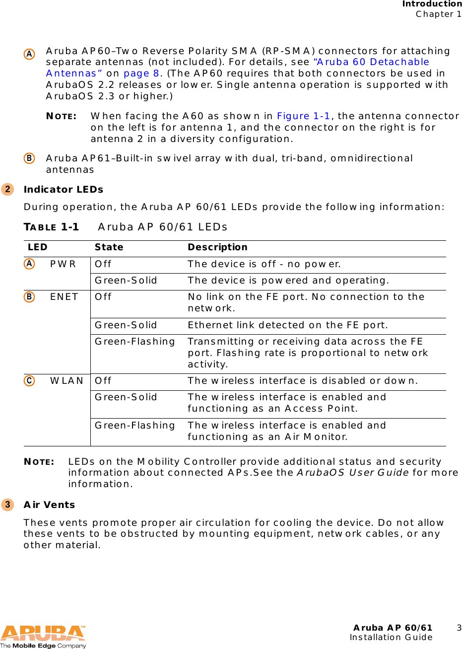
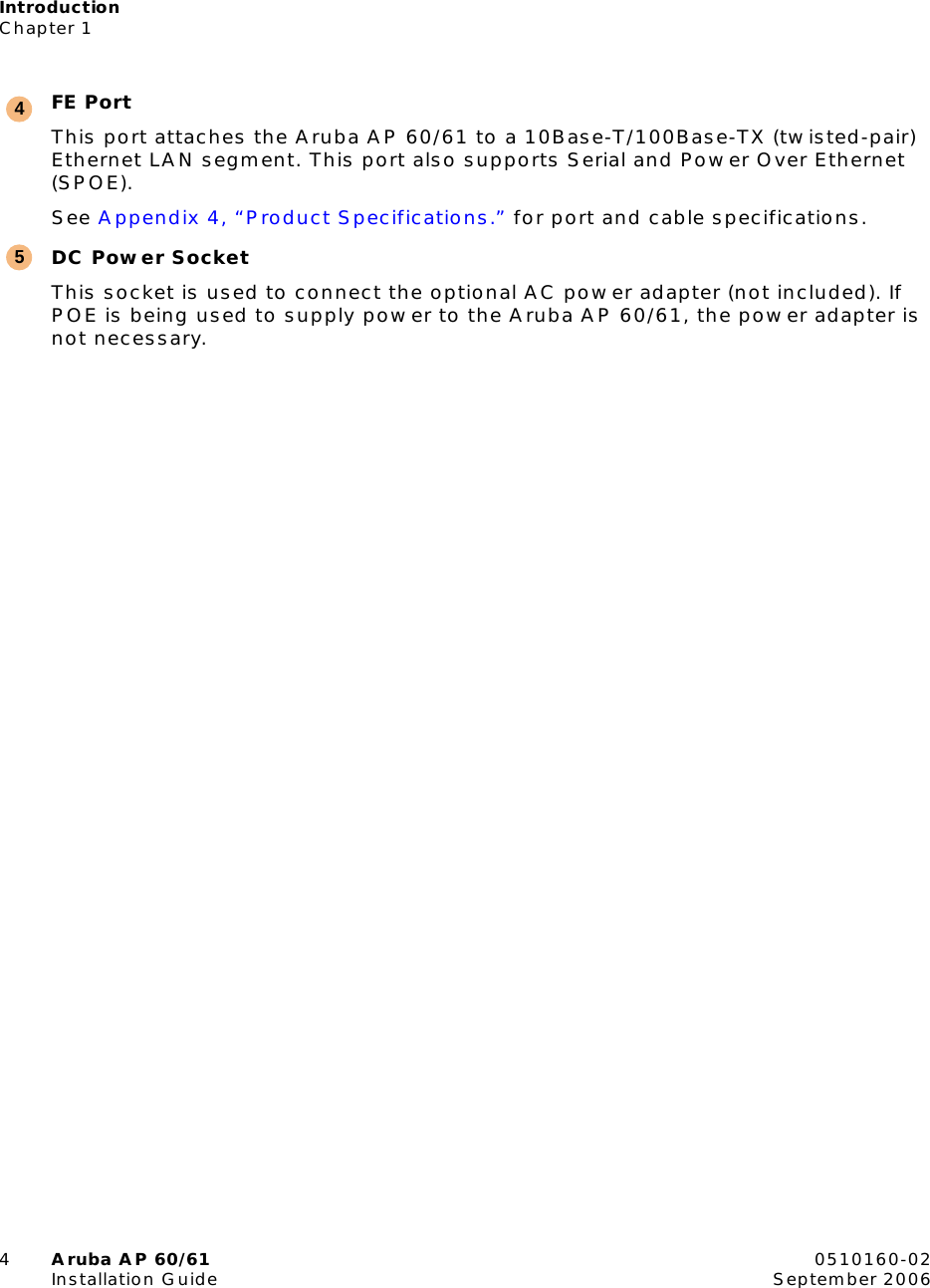
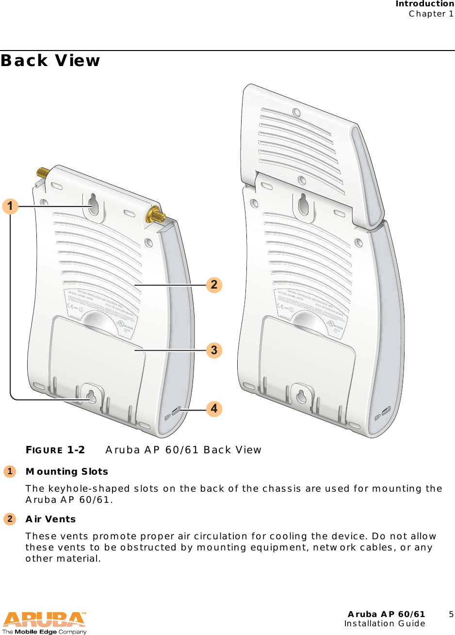
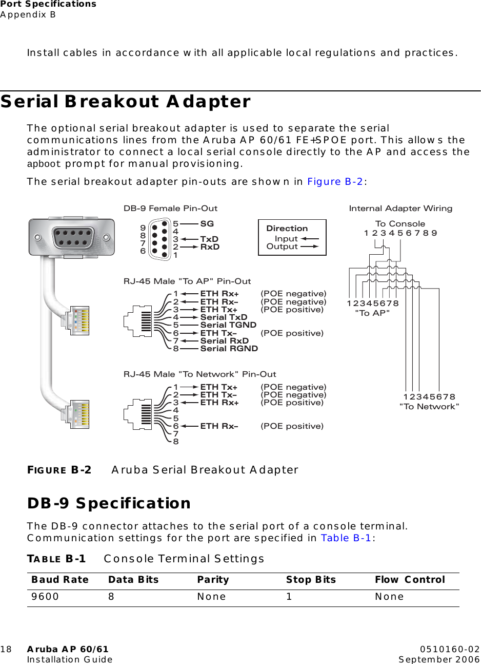
User Manual