Hewlett Packard Enterprise AP70SDR AP 70 Dual-Radio User Manual
Aruba Networks, Inc. AP 70 Dual-Radio
UserManual.wiki
>
Hewlett Packard Enterprise
>
AP70SDR User Manual
>
Users Manual
Contents
1.
Users Manual
2.
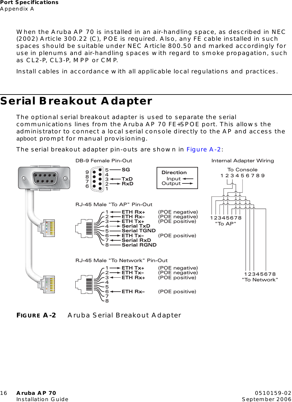
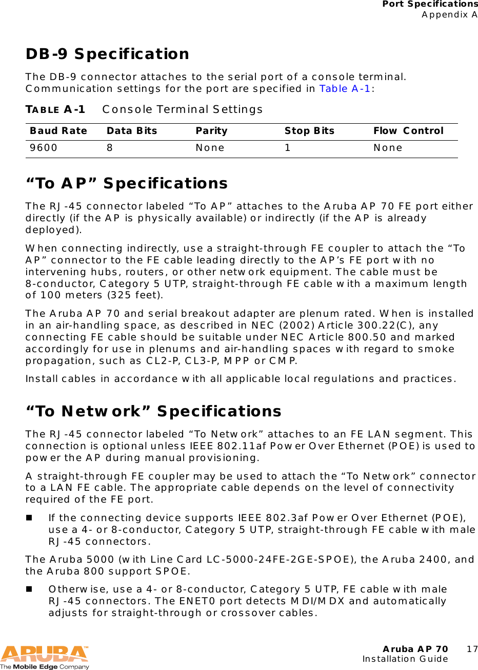
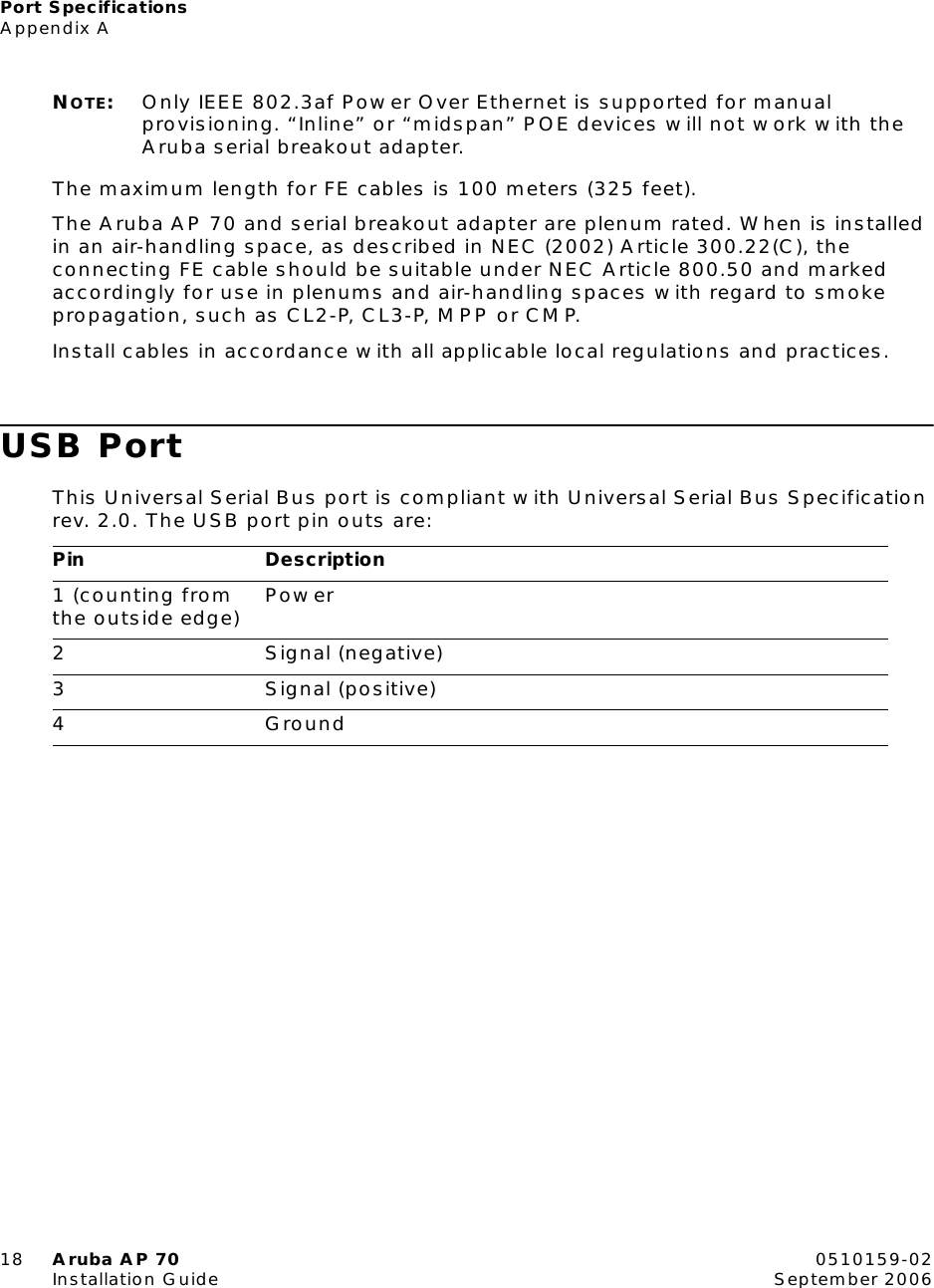
Technical Product Description
Users Manual
Navigation menu
Upload a User Manual
Namespaces
Wiki Guide
HTML
PDF
Info
Views
User Manual
Discussion / Help
Navigation
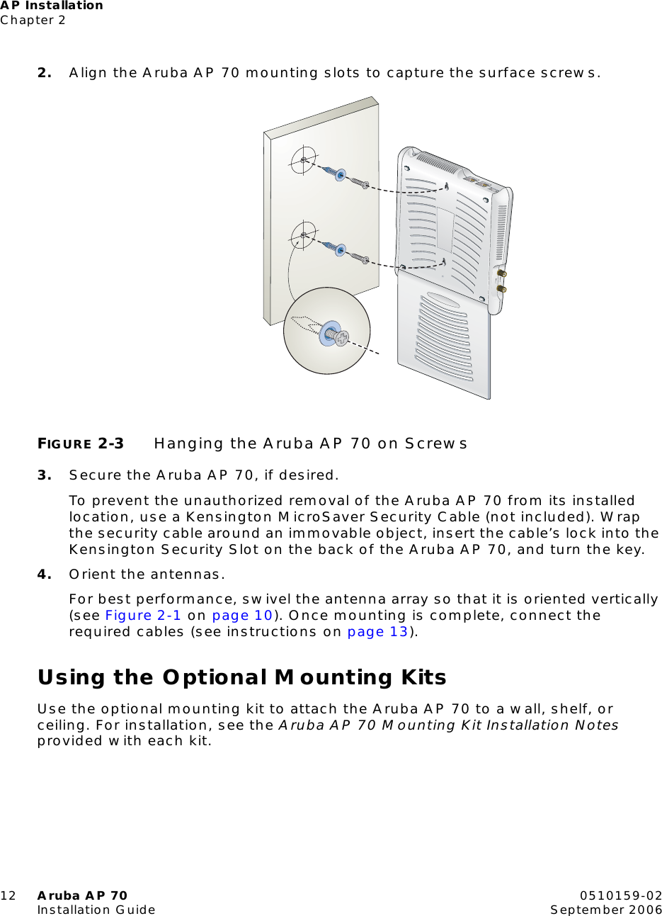
![Prefacevi Aruba AP 70 0510159-02Installation Guide September 2006Text ConventionsThe following conventions are used throughout this manual to emphasize important concepts:TABLE 1 Text ConventionsType Style DescriptionItalics This style is used to emphasize important terms and to mark the titles of books.System items This fixed-width font depicts the following:Sample screen outputSystem promptsFilenames, software devices, and certain commands when mentioned in the textCommands In the command examples, this bold font depicts text that the user must type exactly as shown.<Arguments> In the command examples, italicized text within angle brackets represents items that the user should replace with information appropriate to their specific situation. For example:# send <text message>In this example, the user would type “send” at the system prompt exactly as shown, followed by the text of the message they wish to send. Do not type the angle brackets.[ Optional ] In the command examples, items enclosed in brackets are optional. Do not type the brackets.{ Item A | Item B } In the command examples, items within curled braces and separated by a vertical bar represent the available choices. Enter only one choice. Do not type the braces or bars.](https://usermanual.wiki/Hewlett-Packard-Enterprise/AP70SDR.Users-Manual/User-Guide-820096-Page-6.png)