Hewlett Packard Enterprise AP80 Aruba 80 a+b/g Outdoor Stand-alone Access Point User Manual AP80 Thin user guide
Aruba Networks, Inc. Aruba 80 a+b/g Outdoor Stand-alone Access Point AP80 Thin user guide
UserManual.wiki
>
Hewlett Packard Enterprise
>
AP80 User Manual
Manual
Navigation menu
Upload a User Manual
Namespaces
Wiki Guide
HTML
PDF
Info
Views
User Manual
Discussion / Help
Navigation
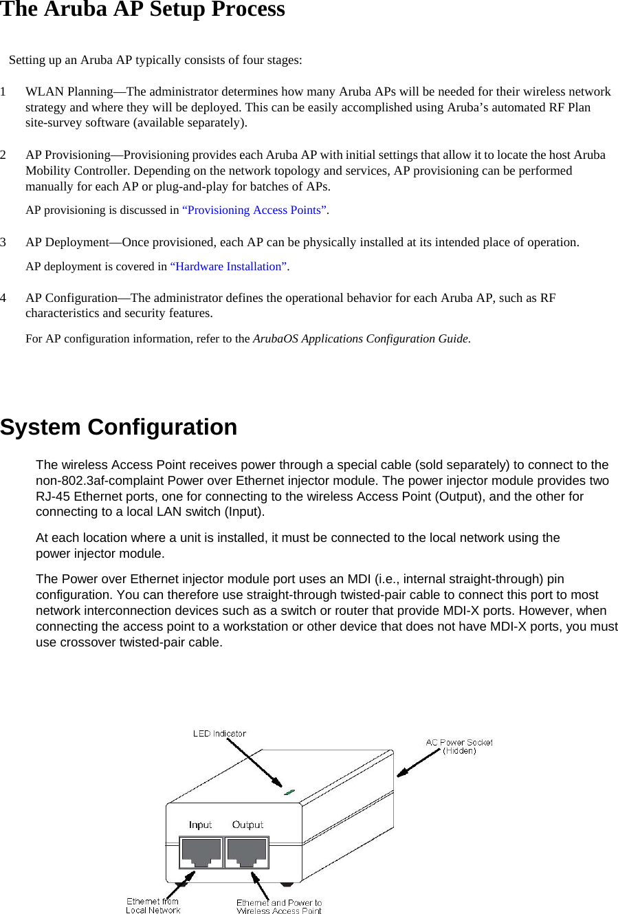
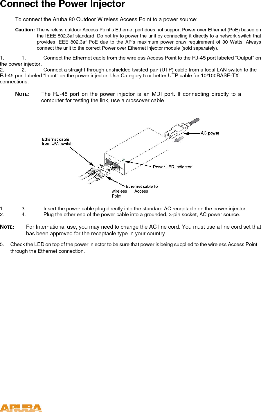
![The wireless bridge offers a variety of management options, including a web-based interface, a command line interface (CLI), or using SNMP management software. Most initial configuration steps can be made through the web browser interface using the Setup Wizard. However, for units that do not have a preset country code, you must first set the country code using the CLI. Note: Units sold in some countries are not configured with a specific country code. You must use the CLI to set the country code and enable wireless operation. The wireless bridge uses the IP address 192.168.1.1 by default. If this address is not compatible with your network, you can first perform initial configuration using a PC that has IP settings compatible with this subnet (for example, 192.168.1.2) and connecting it directly to the wireless bridge. When the basic configuration is completed, you can set new IP settings for the wireless bridge before connecting it to your network. Initial Setup through the CLI The wireless bridge provides access to the CLI through a Telnet connection. You can open a Telnet session by performing these steps: 1. From the host computer, enter the Telnet command and the IP address of the wireless bridge unit (default 192.168.1.1). 2. At the prompt, enter “admin” for the user name. 3. The default password is null, so just press [Enter] at the password prompt. The CLI will display the “Aruba Networks AP-80MB#” prompt to show that you are using executive access mode (i.e., Exec). Username: admin Password: Aruba Networks AP-80MB#](https://usermanual.wiki/Hewlett-Packard-Enterprise/AP80/User-Guide-623180-Page-13.png)
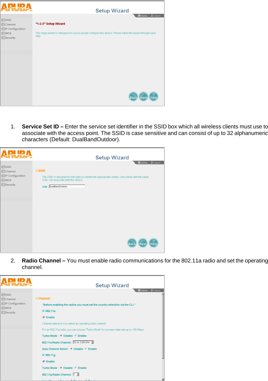
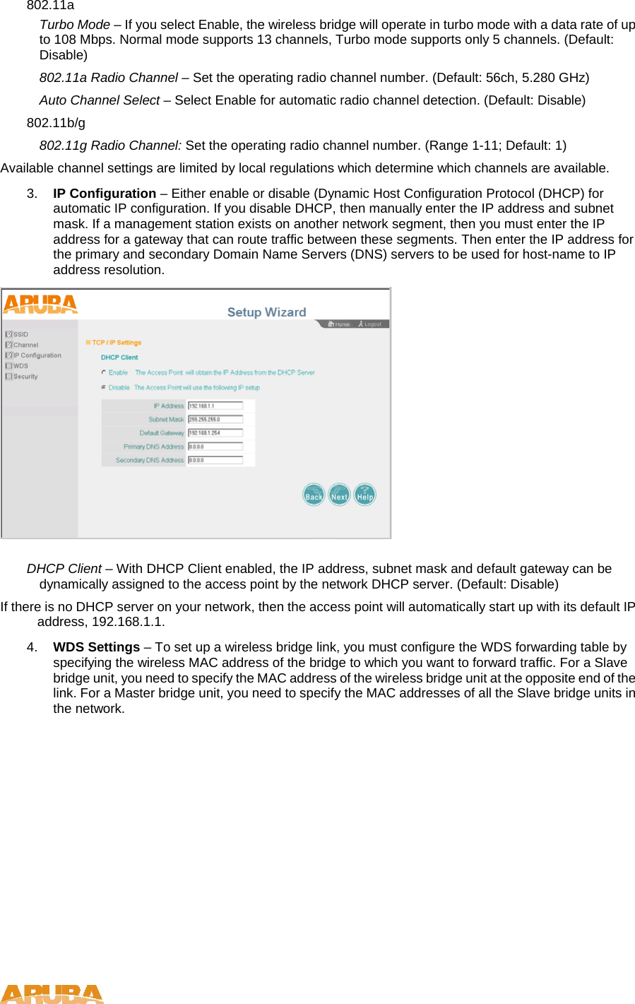
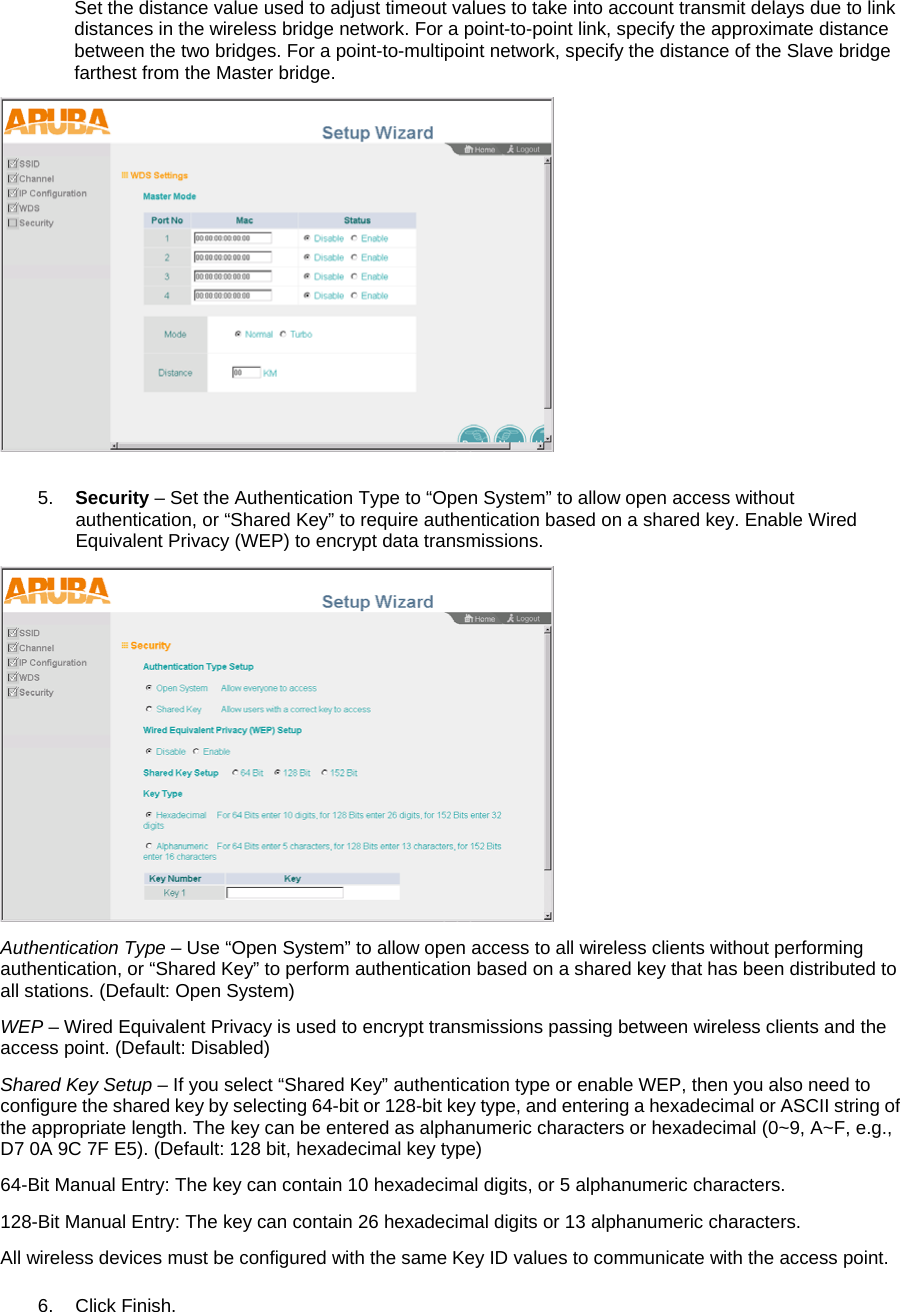
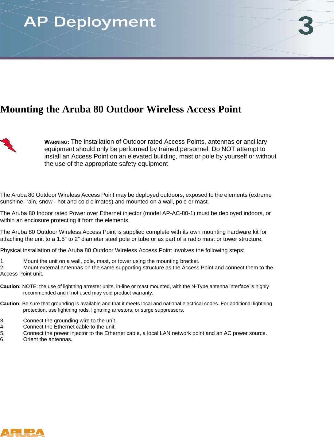
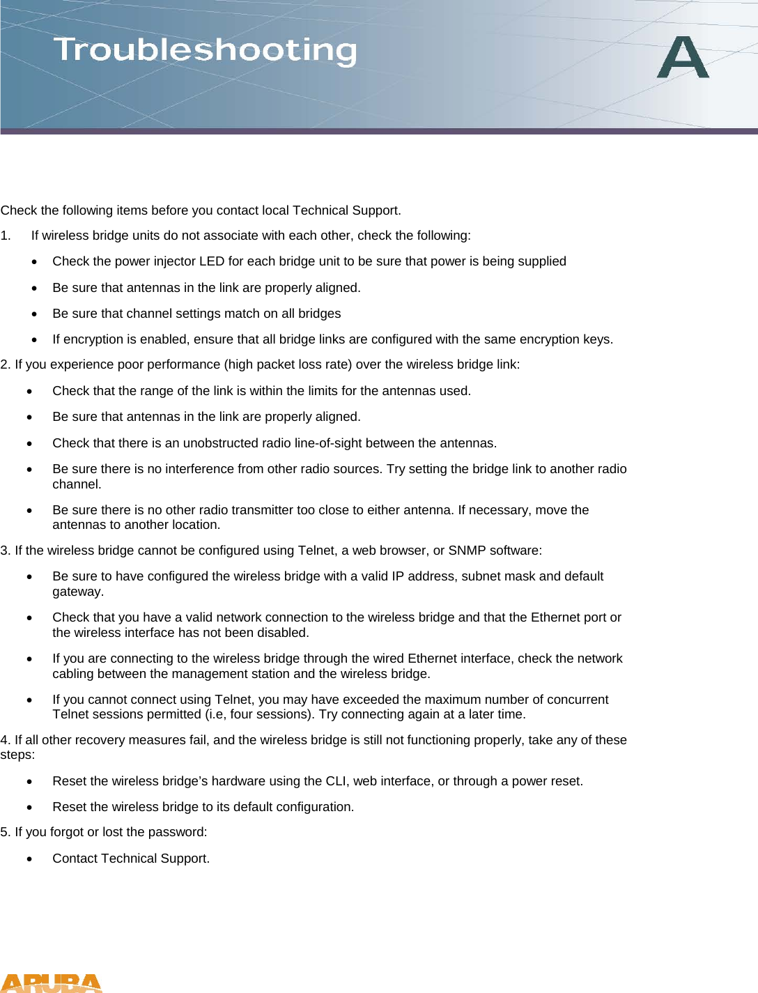
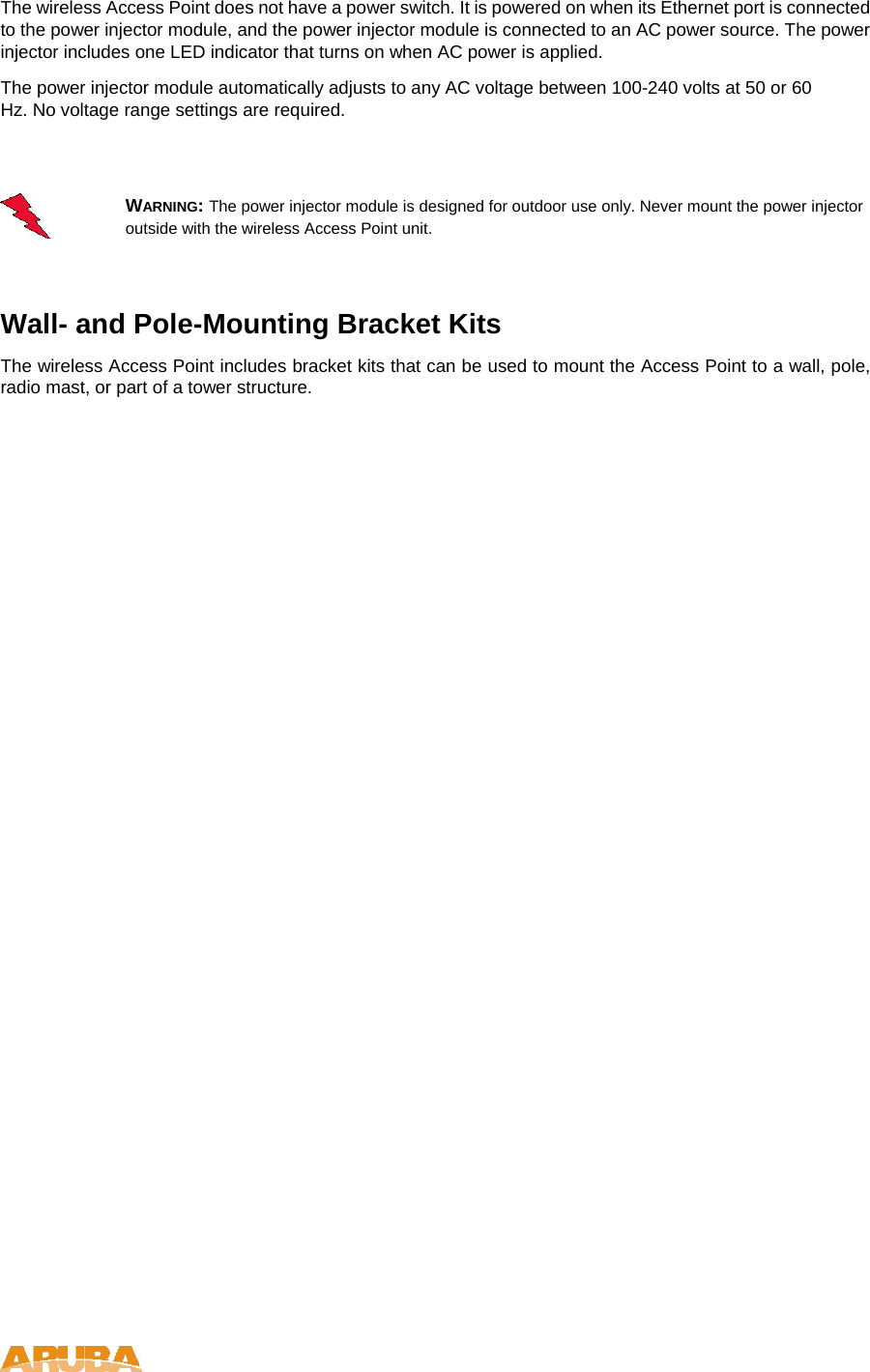
![Using the Web-based Management Setup Wizard There are only a few basic steps you need to complete to set up the wireless bridge for your network. The Setup Wizard takes you through configuration procedures for the radio channel selection, IP configuration, and basic WEP encryption for wireless security. The wireless bridge can be managed by any computer using a web browser (Internet Explorer 5.0 or above, or Netscape Navigator 6.2 or above). Enter the IP configured for the unit or the default IP address: http://192.168.1.1 Logging In – Enter the default username “admin” and click LOGIN (there is no default password). For information on configuring a user name and password. The home page displays the Main Menu. Launching the Setup Wizard – To perform initial configuration, click Setup Wizard on the home page, then click on the [Next] button to start the process.](https://usermanual.wiki/Hewlett-Packard-Enterprise/AP80/User-Guide-623180-Page-15.png)