Hewlett Packard Enterprise AP85 AP-85 Dual-Radio Wireless Access Point User Manual AP 85IG 0510323 02
Aruba Networks, Inc. AP-85 Dual-Radio Wireless Access Point AP 85IG 0510323 02
Contents
- 1. Installation Guide Part 1
- 2. Installation Guide Part 2
- 3. Installation Guide Part 3
Installation Guide Part 2
24 | AP-85 Series Installation Aruba AP-85 Outdoor Access Point Series | Installation Guide
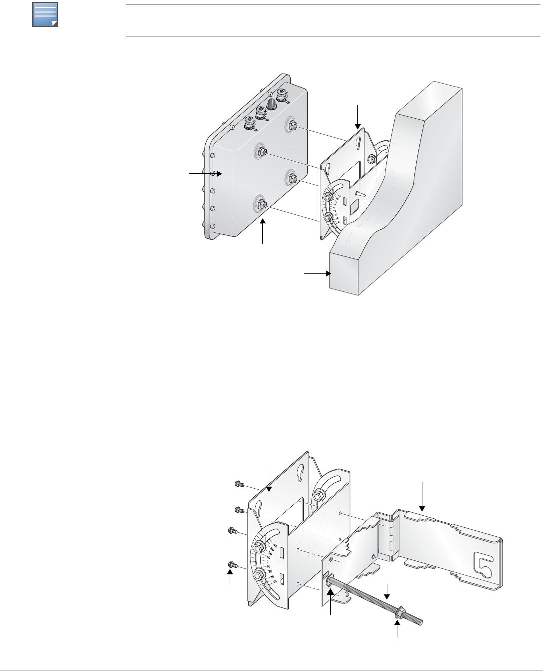
2. Seat the AP-85 into the four keyholes on the mounting plate and tighten down the four mounting
bolts (M8 bolts) to secure the AP-85 in place (see Figure 12). The mounting plate should rest
between the captive flat washer on each of the mounting bolts and the rear of the AP-85.
Figure 12 Wall Mounting the AP-85
Pole Mounting the AP-85 (1.5” to 3.5” Diameter)
To mount an AP-85 to a pole with a diameter of 1.5” to 3.5”:
1. Slide the long T-bolt through the opening in the mounting bracket (see Figure 13).
2. Attach the included retaining clip to the T-bolt (see Figure 13).
3. Screw the included nut onto the end of the T-bolt (see Figure 13).
4. Secure the mounting plate to the mounting bracket using the four included phillips head screws (see
Figure 13).
Figure 13 Assembling the Pole Mounting Bracket
NOTE
The positioning of the keyholes on the mounting plate supports horizontal or vertical mounting of the
AP-85, which is achieved by rotating the device by 90 degrees and securing it to the mounting plate.
Mounting Bolts
Mounting Plate
AP-85
Wall
arun 0137
Nut (1x)
T-Bolt (1x)
Phillips Head Screws (4x)
Mounting Bracket
Mounting Plate
Retaining Clip
Aruba AP-85 Outdoor Access Point Series | Installation Guide AP-85 Series Installation | 25
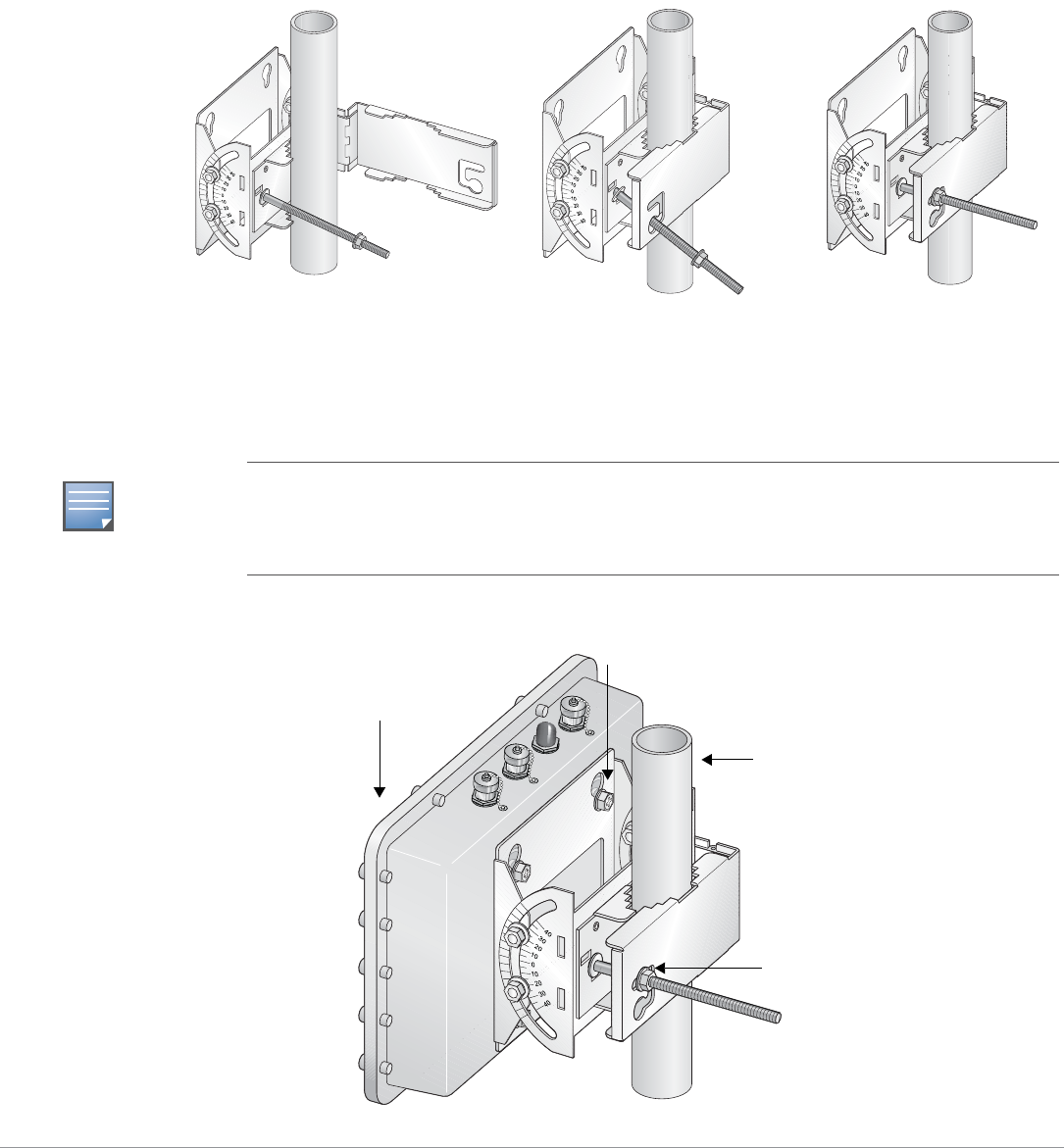
5. Wrap the pole mounting bracket around a 1.5” to 3.5” diameter pole and secure the bracket in place
(see Figure 14).
a. Wrap the pole mounting bracket around the pole.
b. Slip the end of the T-bolt with nut through the opening in the pole mounting bracket.
c. Maneuver the T-bolt to the top slot in the pole mounting bracket and tighten down the nut.
Ensure that the nut is tightly secured and that the bracket cannot move. It must be secure to
support the weight of the AP-85.
Figure 14 Securing the Pole Mounting Bracket
6. Seat the AP-85 into the four keyholes on the mounting plate and tighten down the four mounting
bolts (M8 bolts) to secure the AP-85 in place (see Figure 15). The mounting plate should rest
between the captive flat washer on each of the mounting bolts and the rear of the AP-85.
Figure 15 Vertical Pole Mount Position (1.5” to 3.5” Diameter)
arun_0130
arun_0129
Step A Step B Step C
NOTE
The pole mounting bracket can be secured to a horizontal or vertical pole. The positioning of the
keyholes on the bracket supports horizontal or vertical mounting of the AP-85 on either pole type,
which is achieved by rotating the device by 90 degrees and securing it to the bracket. Refer to
Figure 15 and Figure 16 for details.
Secured
Mounting Bracket
Tightened Mounting Bolts
AP-85
Pole
26 | AP-85 Series Installation Aruba AP-85 Outdoor Access Point Series | Installation Guide
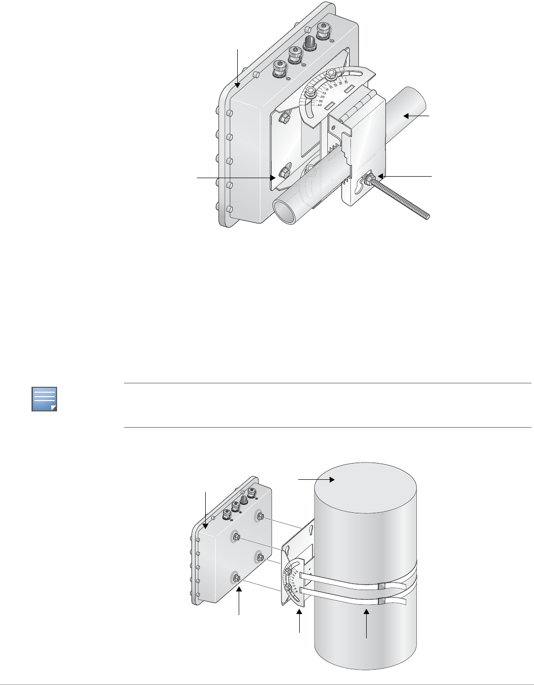
Figure 16 Horizontal Pole Mount Position (1.5” to 3.5” Diameter)
Pole Mounting the AP-85 (>3.5” Diameter)
To mount an AP-85 to a pole with a diameter greater than 3.5”:
1. Attach the mounting plate to the pole using outdoor rated straps (see Figure 17). Outdoor rated
straps are not included with the unit and must be purchased separately.
2. Seat the AP-85 into the four keyholes on the mounting plate and tighten down the four mounting
bolts (M8 bolts) to secure the AP-85 in place (see Figure 17). The mounting plate should rest
between the captive flat washer on each of the mounting bolts and the rear of the AP-85.
Figure 17 Pole Mounting the AP-85 (>3.5” Diameter)
arun_0131C
Secured
Mounting Bracket
Tightened Mounting
Bolts
AP-85
Horizontal Pole
NOTE
The mounting plate can be secured to a horizontal or vertical pole. The positioning of the keyholes
on the mounting plate supports horizontal or vertical mounting of the AP-85 on either pole type,
which is achieved by rotating the device by 90 degrees and securing it to the mounting plate.
Outdoor Rated Straps
Mounting Plate
Mounting Bolts
AP-85 Pole
Aruba AP-85 Outdoor Access Point Series | Installation Guide AP-85 Series Installation | 27
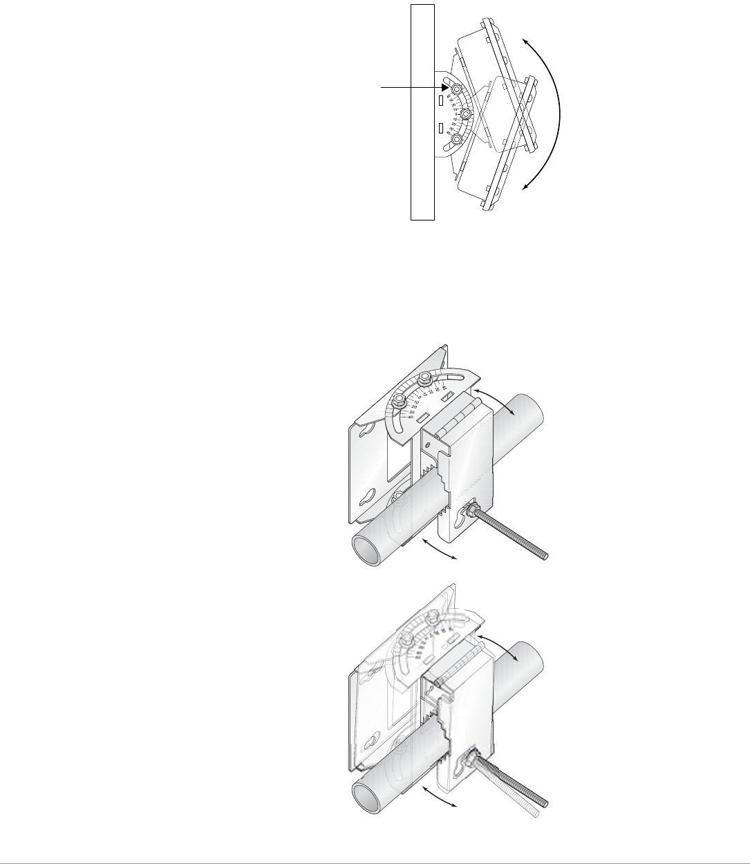
Positioning the AP-85
To adjust the angle of an AP-85 on a vertical pole:
1. Loosen the four M8 bolts on the side of the mounting plate and rotate the AP to the desired angle
and tighten down the M8 bolts (see Figure 18).
Figure 18 Positioning the AP-85 on a Vertical Pole
To adjust the angle of an AP-85 on a horizontal pole:
1. Rotate the entire mounting bracket to the desired angle and tighten the bracket into place (see
Figure 19).
Figure 19 Positioning the AP-85 on a Horizontal Pole
M8 Positioning Bolts
(4x, 2x per side)
arun_0131D
arun_0131E
28 | AP-85 Series Installation Aruba AP-85 Outdoor Access Point Series | Installation Guide
Connecting Required Cables
RJ-45 CAT 5 Cable
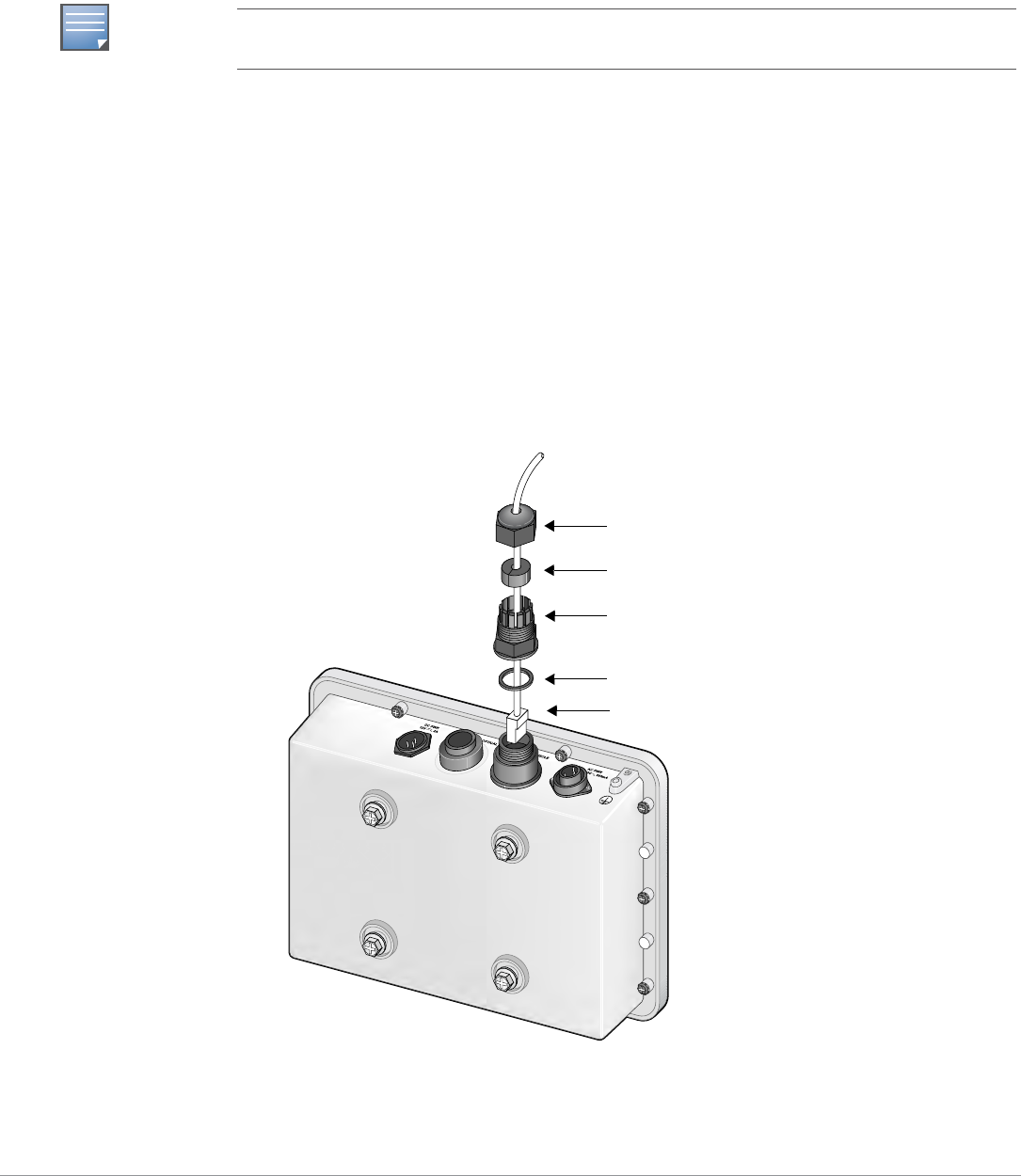
To weatherproof and connect an RJ-45 terminated CAT 5E or better cable to an AP-85 (see Figure 20),
perform the following using the contents in the included kit that ships with your unit:
1. Slide the cap over the terminated cable.
2. Slide the rubber grommet over the terminated cable.
3. Slide the connector shell over the terminated cable.
4. Slide the washer over the terminated cable.
5. Insert the rubber grommet into the top of the connector shell until the top surface of the grommet is
flush with the top edge of the connector shell.
6. Connect the terminated cable to the proper port: LAN/POE port on the AP-85TX model or the
CONSOLE port on the AP-85FX/LX models.
7. Screw the connector shell onto the interface on the AP-85.
8. Screw the cap onto the connector shell.
Figure 20 Weatherproofing and Connecting an RJ-45 Terminated CAT 5 Cable
NOTE
The cable is not included and must be purchased separately. Purchase a suitable UV resistant,
outdoor rated, CAT 5E or better RJ-45 cable for use with the AP-85.
arun_0127
Cap
Rubber Grommet
Connector Shell
Washer
Terminated CAT 5E or Better Cable
Aruba AP-85 Outdoor Access Point Series | Installation Guide AP-85 Series Installation | 29
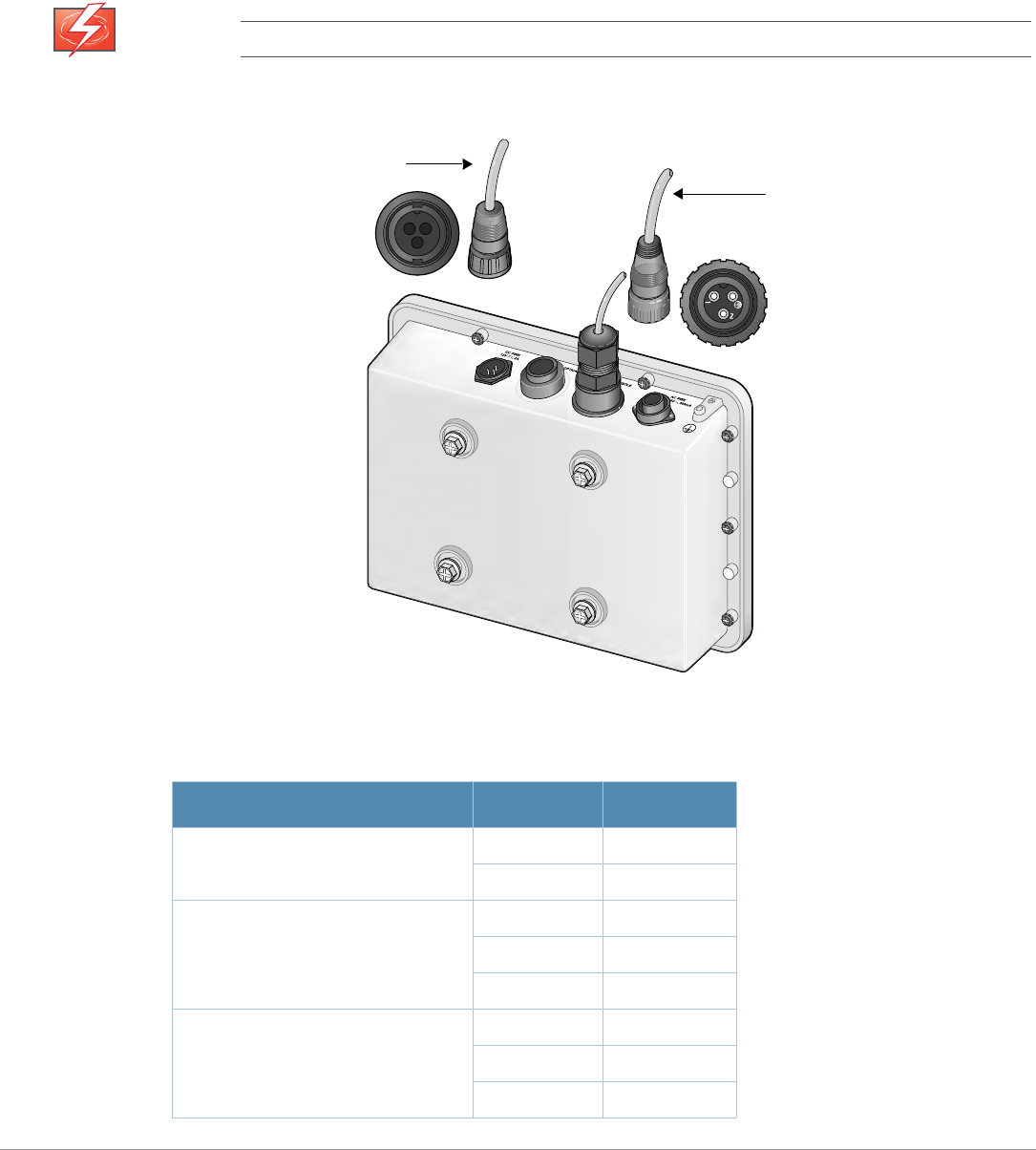
DC and AC Power Cables
To connect the power cables (wiring harnesses):
1. Screw the two-wire, 8-foot long DC power cable (wiring harness) to the DC interface on the AP-
85TX, AP-85FX, or AP-85LX model.
2. Screw the three-wire, 8-foot long AC power cable (wiring harness) to the AC interface on the AP-
85FX or AP-85LX models only.
Figure 21 Connecting Power
WARNING
Disconnect the AC mains before handling the AC power cable and connecting it to the AP-85.
Table 5 AC and DC Power Cable Descriptions
Cable Type Wire Color Assignment
DC Power Cable Red +12V
Black Ground
AC Power Cable: United States (US) Black Line
White Neutral
Green Ground
AC Power Cable: Europe (EU) Brown Line
Blue Neutral
Green/Yellow Ground
arun_0128B
DC Power Cable
AC Power Cable

30 | AP-85 Series Installation Aruba AP-85 Outdoor Access Point Series | Installation Guide
Fiber Optic Cable
To utilize the fiber optic termination kit that ships with the AP-85FX/LX models:
1. Follow the instructions in the included Tyco document: Instruction Sheet 408-10079.
Lightning Arrestor Installation
Refer to the instructions that ship with the Aruba lightning arrestor (AP-LAR-1).
Antenna Installation
Refer to the instructions that ship with your Aruba outdoor rated antenna.
4. Verifying Post-Installation Connectivity
The integrated LEDs on the AP-85 can be used after installation to verify that the AP is receiving power,
is initializing successfully, and that wireless connectivity is occurring (see LED Status Indicators on
page 12). Refer to the ArubaOS Quick Start Guide for further details on verifying post-installation
network connectivity.
5. Configuring the AP-85
AP Configuration
Configuration parameters are network or controller specific and are configured and stored on the
Mobility Controller. Network configuration settings are pushed out to the AP(s) but remain stored on
the Mobility Controller. Configuration settings can be configured via the ArubaOS Web UI, ArubaOS
CLI, or Aruba MMS. Refer to their respective guides for further details: the ArubaOS User Guide or
Aruba Mobility Management System User Guide.
NOTE
Fiber optic cables are not included and must be purchased separately. Purchase a suitable UV
resistant, outdoor rated, multi-mode fiber optic cable for use with the AP-85FX and a single-mode
fiber optic cable for use with the AP-85LX.
Aruba AP-85 Outdoor Access Point Series | Installation Guide Understanding Antennas | 31
Appendix A
Understanding Antennas
Aruba Antennas
Before you can select the antenna type needed for the deployment, read the basic wireless antenna
information provided in this section. This information will help you understand wireless antenna basics
and Aruba antenna specifications.
Understanding Wireless Antennas
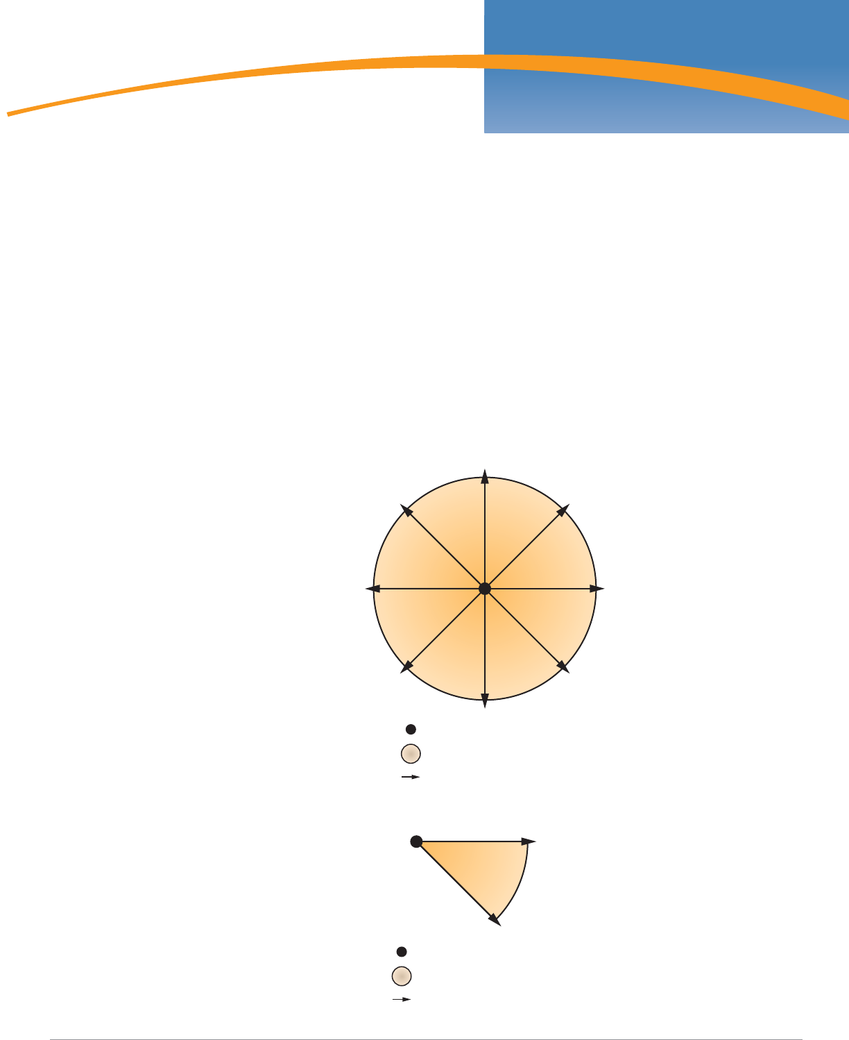
Omni-Directional vs. Directional Coverage
For optimal performance of your wireless network, it is essential to understand the purpose behind
proper antenna selection. Choosing the correct antenna type will ensure that RF energy is being
directed to the correct coverage areas. Omni-directional antennas provide equal coverage in all
directions (see Figure 22), while directional antennas point RF energy in a specific direction for RF
concentration within a targeted area (see Figure 23).
Figure 22 Omni-Directional Antenna
Figure 23 Directional Antenna
Antenna Location
Area of Coverage
Direction of Coverage
Antenna Location
Area of Coverage
Direction of Coverage
32 | Understanding Antennas Aruba AP-85 Outdoor Access Point Series | Installation Guide
Antenna Beamwidth, Pattern, and Gain Considerations
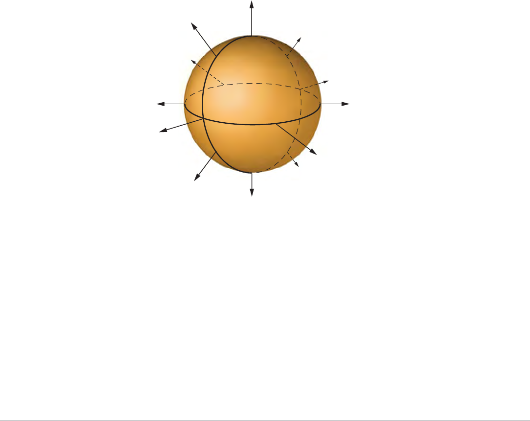
Antenna gain is a relative measure of how the antenna compares to an ideal isotropic radiator. An ideal,
isotropic radiator would radiate power in all directions equally over a sphere. The relationship between
gain, power, and propagation distance is detailed already in textbooks and Wiki's, so these expressions
are not repeated here. Antenna gain is often confused with power gain in amplifiers, but it is important
to note that antenna gain only makes a transmitter's power appear to be higher than would be predicted
by calculation of the power fed to the antenna and then spread equally over a sphere. Antenna gain
itself is a completely passive and bi-directional property, determined only by the shape and
construction of the antenna.
Knowing that gain is only a comparison of the apparent power to the power that would be required if
fed to an ideal isotropic antenna, you realize that gain can only be created by distorting the antenna
pattern from the ideal spherical pattern. Think of this as focusing the same power that would normally
distribute evenly over a sphere into a tighter region of space. Thus, the higher the gain, the more
concentrated (in some way) the antenna pattern must be in order to achieve that gain.
Example
To visualize the concept of gain, picture a rubber ball. The surface area of the ball represents the total
available power radiated by an ideal isotropic antenna over its sphere of radiation (see Figure 24).
Figure 24 Equal Signal Strength Radiated in All Directions
Equal Signal Strength
Radiated over a Sphere
Aruba AP-85 Outdoor Access Point Series | Installation Guide Understanding Antennas | 33
Now, still using the same ball with the same available surface area, how would you be able to stretch
the ball farther out? One way is to press down on the top of the ball and squash it down vertically. This
would keep the same basic shape in the horizontal plane (round), but it would force the ball to stretch,
creating a pancake shape, in the vertical direction (see Figure 25). This represents the concept of the
high gain omni-directional antenna, which achieves a greater coverage distance in the horizontal
direction at the expense of coverage in the vertical areas of the radiating sphere.
Figure 25 High Gain Omni-Directional Antenna
To stretch the ball primarily in one direction (instead of in all directions), push the ball, both vertically
and horizontally, on the sides and on the back, to force the ball to deform in a single direction. This
action would significantly distort the shape of the original ball both horizontally and vertically, but it
will allow you to stretch the same ball a lot farther in one direction (see Figure 26). This represents the
concept of the high gain directional antenna, which is designed to compress the entire radiating sphere
into a single predominate direction.
Figure 26 High Gain Directional Antenna
High Gain
Omni-Directional Antenna
Compressed vertical signal,
which expands signal
horizontally
NOTE
Gain is created by forcing transmitted power to radiate in a preferred direction rather than radiating
in all directions of an ideal sphere. Therefore, a high gain signal is always accompanied by loss of
available signal in some other portion of the ideal sphere. High gain directional antennas are ideal for
sites requiring directed coverage in a specific area or extended range for bridging applications, but
they are not suited for sites requiring uniform coverage in large areas. It is important to keep in mind
that both vertical and horizontal coverage can be affected by the use of a higher gain antenna and
beamwidth (a measure of coverage) is always inversely related to gain.
High Gain Directional Antenna
Entire sphere compressed into a
single predominate direction, focusing
RF energy to a targeted area of
coverage
34 | Understanding Antennas Aruba AP-85 Outdoor Access Point Series | Installation Guide
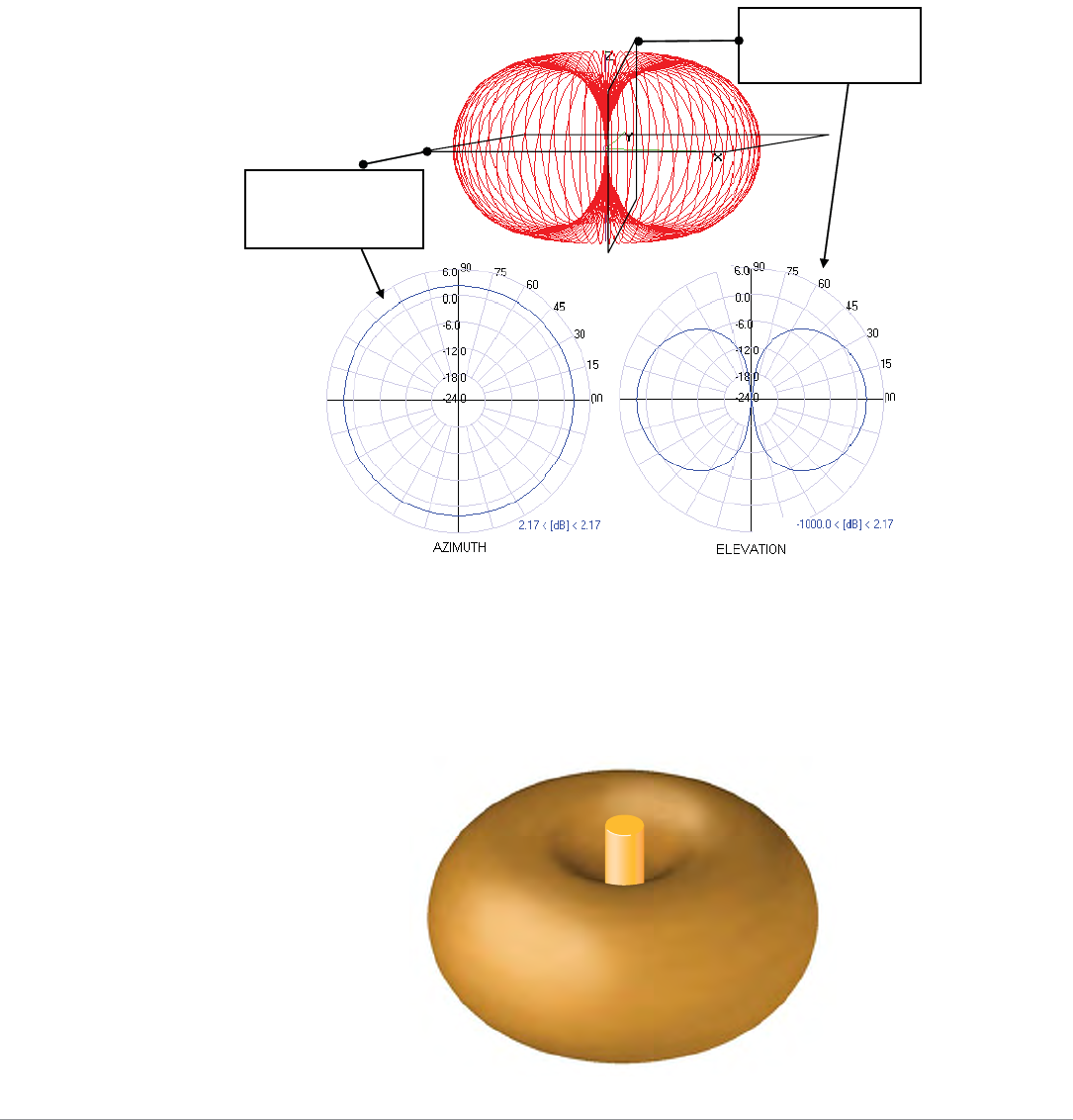
Understanding Antenna Pattern Plots and Specifications
Traditional 2-D pattern plots and beamwidth specifications are like mental puzzles waiting to be solved
because they only provide a snapshot of the information in two planes. These two planes are often
referred to as the azimuth (H-plane or horizontal) and elevation (vertical or E-plane) planes. The
azimuth view would be considered the view from directly above, viewing the antenna pattern on the
horizontal plane. The elevation view is considered to be a side view, viewing the antenna pattern on the
vertical plane. It is helpful to think of these planes as “cuts” of the real antenna pattern, which is
actually 3-D. Figure 27 illustrates where these “cuts” are located for a typical omni-directional antenna
pattern.
Figure 27 Antenna Pattern Conventions (Omni-Directional Pattern Shown)
The antenna illustrated by Figure 27 is commonly referred to as the dipole pattern because it is the
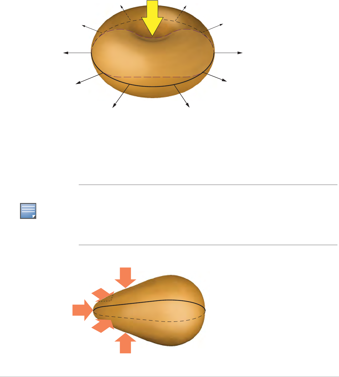
pattern produced by an ideal dipole antenna. The gain of this antenna is 2.14, which is achieved by
compression in the vertical plane (elevation) compared to the ideal sphere. If referring to the true 3D
pattern, this compression is sometimes called the donut shape (see Figure 28).
Figure 28 Donut Shape Compression of an Omni-Directional Antenna
Azimuth, H-plane,
or Horizontal
Pattern Diagram
Elevation, E-plane,
or Vertical Pattern
Diagram