Hewlett Packard Enterprise AP85FXLX Aruba AP-85FX and AP-85LX Access Points User Manual AP 85IG 0510323 06
Aruba Networks, Inc. Aruba AP-85FX and AP-85LX Access Points AP 85IG 0510323 06
Users Manual

Aruba AP-85 Outdoor
Access Point Series
Installation Guide

www.arubanetworks.com
1344 Crossman Avenue
Sunnyvale, California 94089
Phone: 408.227.4500
Fax 408.227.4550
Aruba AP-85 Outdoor Access Point Series | Installation Guide 0510323-06 | October 2008
Copyright
© 2008 Aruba Networks, Inc. AirWave®, Aruba Networks®, Aruba Mobility Management System®, Bluescanner, For Wireless That
Works®, Mobile Edge Architecture®, People Move. Networks Must Follow®, RFprotect, The All Wireless Workplace Is Now Open For
Business, Green Island, and The Mobile Edge Company® are trademarks of Aruba Networks, Inc. All rights reserved. All other trademarks
are the property of their respective owners.
Open Source Code
Certain Aruba products include Open Source software code developed by third parties, including software code subject to the GNU
General Public License (GPL), GNU Lesser General Public License (LGPL), or other Open Source Licenses. The Open Source code used
can be found at this site:
http://www.arubanetworks.com/open_source
Legal Notice
The use of Aruba Networks, Inc. switching platforms and software, by all individuals or corporations, to terminate other vendors’ VPN
client devices constitutes complete acceptance of liability by that individual or corporation for this action and indemnifies, in full, Aruba
Networks, Inc. from any and all legal actions that might be taken against it with respect to infringement of copyright on behalf of those
vendors.
Warranty
This hardware product is protected by the standard Aruba warranty of one year parts/labor. For more information, refer to the
ARUBACARE SERVICE AND SUPPORT TERMS AND CONDITIONS.
Altering this device (such as painting it) voids the warranty.

Aruba AP-85 Outdoor Access Point Series | Installation Guide |3
Contents
Preface ................................................................................................................................... 5
Guide Overview .....................................................................................................5
Related Documents ...............................................................................................5
Contacting Aruba Networks ..................................................................................6
Chapter 1 AP-85 Series Hardware Overview .......................................................... 7
About the AP-85 Series .........................................................................................7
AP-85 Series Operation ..................................................................................7
Minimum Software Requirements .........................................................................8
Package Checklist.................................................................................................8
Hardware Model Overview ....................................................................................9
AP-85 Series Front View...........................................................................9
AP-85 Series Rear View............................................................................9
AP-85 Series Top View...........................................................................10
AP-85TX Bottom View............................................................................10
AP-85FX/LX Bottom View.......................................................................11
LED Status Indicators ...................................................................................13
Optional Accessories...........................................................................................14
Chapter 2 Outdoor Planning and Deployment Considerations........................... 15
Planning and Deployment Considerations ..........................................................15
Scale Requirements ......................................................................................15
Identifying Known RF Absorbers/Reflectors/Interferences Sources ............15
RF Absorbers..........................................................................................15
RF Reflectors ..........................................................................................15
RF Interference Sources.........................................................................16
Line of Sight (Radio Path Planning)...............................................................16
Antenna Height .............................................................................................17
Antenna Position and Orientation .................................................................18
Radio Interference.........................................................................................19
Weather Conditions ......................................................................................19
Ethernet Cabling ...........................................................................................19
Grounding .....................................................................................................19
Chapter 3 AP-85 Series Installation....................................................................... 21
Pre-Installation Network Setup............................................................................21
Pre-Installation Checklist ..............................................................................21
Access Point Setup .............................................................................................21
Verifying Pre-Installation Connectivity ..........................................................22
Provisioning the AP.......................................................................................22
Installing the AP-85.......................................................................................22
Mounting the AP-85 ...............................................................................23
Positioning the AP-85.............................................................................27
Connecting Required Cables..................................................................28
Lightning Arrestor Installation.................................................................31
Antenna Installation ................................................................................31
Verifying Post-Installation Connectivity ........................................................32

4|Aruba AP-85 Outdoor Access Point Series | Installation Guide
Configuring the AP-85...................................................................................32
Appendix A Understanding Antennas ...................................................................... 33
Aruba Antennas ...................................................................................................33
Understanding Wireless Antennas................................................................33
Omni-Directional vs. Directional Coverage ............................................33
Antenna Beamwidth, Pattern, and Gain Considerations ........................34
Understanding Antenna Pattern Plots and Specifications .....................36
Detachable Antenna Selection......................................................................37
Detachable Outdoor Antenna Types ......................................................37
Detachable Antenna Selection Tips........................................................37
Appendix B Product Specifications.......................................................................... 43
Mechanical (AP-85TX, AP-85FX, and AP-85LX) ...........................................43
Electrical........................................................................................................43
AP-85TX .................................................................................................43
AP-85FX .................................................................................................44
AP-85LX..................................................................................................44
Maximum Power Draw ...........................................................................44
Wireless LAN.................................................................................................44
Safety and Regulatory Compliance.....................................................................45
Declaration of Conformity .............................................................................45
European Headquarters .........................................................................46
Instructions for Use in a Potentially Explosive Atmosphere................................46
Proper Disposal of Aruba Equipment..................................................................47
Waste of Electrical and Electronic Equipment ..............................................47
European Union RoHS..................................................................................48
China RoHS ..................................................................................................48
Index..................................................................................................................................... 49

Aruba AP-85 Outdoor Access Point Series | Installation Guide Preface | 5
Preface
This preface includes the following information:
zAn overview of the contents of this manual
zA list of related documentation for further reading
zAruba Networks support and service information
Guide Overview
zChapter 1, “AP-85 Series Hardware Overview” on page 7 provides a detailed hardware overview of the three AP-85
models: the AP-85TX, the AP-85FX, and the AP-85LX.
zChapter 2, “Outdoor Planning and Deployment Considerations” on page 15 provides key questions to ask and items to
consider when deploying an outdoor wireless network.
zChapter 3, “AP-85 Series Installation” on page 21 describes the multi-step process for successful installation and
deployment of an AP-85.
zAppendix A, “Understanding Antennas” on page33 provides key tools that will help you understand Aruba antenna
specifications.
zAppendix B, “Product Specifications” on page43 includes product technical specifications and safety and regulatory
compliance information.
Related Documents
The following documents are referred to in this guide and are considered components of the complete documentation set
needed for successful AP deployment and management:
z
ArubaOS Quick Start Guide
z
ArubaOS User Guide
z
Aruba Mobility Management System User Guide
zAruba Outdoor Antenna Specifications

6| Preface Aruba AP-85 Outdoor Access Point Series | Installation Guide
Contacting Aruba Networks
Web Site Support
Main Site http://www.arubanetworks.com
Support Site https://support.arubanetworks.com
Software Licensing Site https://licensing.arubanetworks.com/login.php
Wireless Security Incident
Response Team (WSIRT)
http://www.arubanetworks.com/support/wsirt.php
Support Emails
zAmericas and APAC support@arubanetworks.com
zEMEA emea.support@arubanetworks.com
WSIRT Email
Please email details of any security
problem found in an Aruba product.
wsirt@arubanetworks.com
Telephone Support
Aruba Corporate +1 (408) 227-4500
FAX +1 (408) 227-4550
Support
zUnited States 800-WI-FI-LAN (800-943-4526)
zUniversal Free Phone Service Number
(UIFN): Australia, Canada, China,
France, Germany, Hong Kong, Ireland,
Israel, Japan, Korea, Singapore, South
Africa, Taiwan, and the UK.
+800-4WIFI-LAN (+800-49434-526)
zAll Other Countries +1 (408) 754-1200

Aruba AP-85 Outdoor Access Point Series | Installation Guide AP-85 Series Hardware Overview | 7
Chapter 1
AP-85 Series Hardware
Overview
About the AP-85 Series
The AP-85 Series consists of resilient, environmentally hardened, outdoor rated, dual-band IEEE 802.11a/b/g devices, which
can be configured for deployment as a wireless access point, air monitor, mesh point, or mesh portal. This outdoor access
point series is part of Aruba’s comprehensive wireless network solution. The AP-85 Series works only in conjunction with an
Aruba Mobility Controller and each AP can be centrally managed, configured, and upgraded through the controller.
The AP-85 Series consists of the following models:
zAP-85TX (Ethernet)
zAP-85FX (Multi-mode Fiber)
zAP-85LX (Single-mode Fiber)
AP-85 Series Operation
zWireless access point (IEEE 802.11 a/b/g)
zWireless air monitor (IEEE 802.11 a/b/g)
zWireless access point with wireless backhaul support*
zEnterprise mesh point (MP; Mesh license required)*
zEnterprise mesh portal (MPP; Mesh license required)*
zProtocol-independent networking functionality
zIEEE 802.3af Power over Ethernet (PoE) compatible (AP-85TX only)
NOTE
Items noted with a asterisk (*) require a secure enterprise mesh license. Contact your Aruba sales
representative for a complete listing of available software licenses.
!
CAUTION
Aruba access points must be installed by trained service personnel. These installers are responsible
for ensuring that grounding is available and it meets applicable local and national electrical codes.
WARNING
Do not work on an AP and do not connect or disconnect cables during periods of lightning activity.

8| AP-85 Series Hardware Overview Aruba AP-85 Outdoor Access Point Series | Installation Guide
Minimum Software Requirements
The AP-85 Series requires ArubaOS 3.2.0 or later.
ArubaOS software builds prior to version 3.2.0 do not support the AP-85 Series. If your network currently runs on a software
build prior to 3.2.0, you must upgrade the software on your master and local controllers to 3.2.0 or later prior to installing an
AP-85 in your existing network.
Package Checklist
Included with all three AP-85 models:
zAruba AP-85 outdoor access point (TX, FX, or LX model)
zAP-85 wall/pole/mast mount kit (fixture with hardware)
z8-foot DC outdoor rated power cable
zWeatherproof connector shell for RJ-45 terminated CAT 5 cable
LTW P/N LTWRJS-00PFFA-SL8001
z
Aruba AP-85 Outdoor Access Point Installation Guide
Included with the AP-85FX/LX models only:
z8-foot AC outdoor rated power cable (for FX/LX models only; US and EU options available)
zFiber Optic Termination Kit
AP-85FX: Tyco P/N 1828618-1
AP-85LX: Tyco P/N 1828618-2
NOTE
Inform your supplier if any parts are incorrect, missing, or damaged. If possible, retain the carton,
including the original packing materials. Use these materials to repack and return the unit to the
supplier if needed.
NOTE
Optional accessories are available for use with the AP-85 and are sold separately. Refer to "Optional
Accessories" on page14 for further details.
Aruba AP-85 Outdoor Access Point Series | Installation Guide AP-85 Series Hardware Overview | 9
Hardware Model Overview
AP-85 Series Front View
The front of the AP-85 Series has LED status indicators (see Figure 1). For descriptions of the LEDs and their behavior, refer
to "LED Status Indicators" on page13.
Figure 1 AP-85 Series Front View
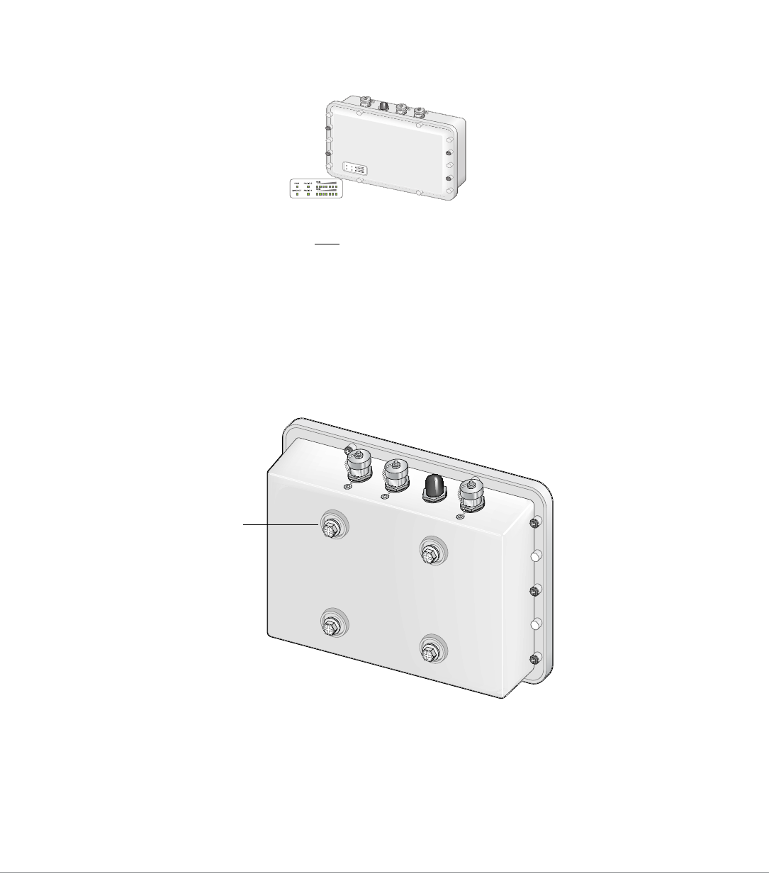
AP-85 Series Rear View
The rear of the AP-85 Series has four mounting holes (see Figure 2). Refer to Chapter 3, “AP-85 Series Installation” on
page 21 for mounting and installation instructions.
Figure 2 AP-85 Series Rear View
arun_0100
LED
Status Indicators
Mounting Holes
10 | AP-85 Series Hardware Overview Aruba AP-85 Outdoor Access Point Series | Installation Guide
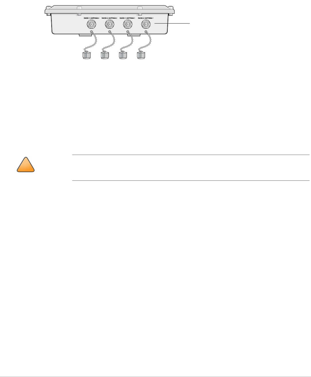
AP-85 Series Top View
The top of the AP-85 Series consists of four, female N-type antenna interfaces (see Figure 3).
Figure 3 AP-85 Series Top View
The AP-85 Series requires the use of detachable, outdoor rated antennas. Select the correct antenna type to support the
required frequency band (2.4 or 5 GHz) and the desired coverage pattern.
The four, female N-type antenna interfaces on the AP-85 models are grouped into diversity pairs, one pair is marked as
RADIO 0 and the other pair is marked as RADIO 1. RADIO 0 supports 2.4 GHz frequency band antennas and RADIO 1
supports 5 GHz frequency band antennas.
To select the correct antenna type for the deployment, download and read Aruba’s outdoor antenna specifications: http://
www.arubanetworks.com/products/access-points/antennas.php.
For further details, see Appendix A, “Understanding Antennas” on page33.
AP-85TX Bottom View
The bottom of the AP-85TX unit (see Figure 5) has the following ports and connections:
zDC PWR 12 VDC, 2 A: The AP is capable of accepting DC power in the range of 8 to 16 VDC. If the AP-85TX is not
connected to a PoE source, the AP must be powered via a DC power source. An outdoor rated, two-wire, 8-foot long DC
power cable (wiring harness) is supplied with the unit. For proper installation instructions, see "DC and AC Power
Cables" on page30.
zLAN/POE 48 VDC, 350 mA: Also known as a 10/100Base-T Fast Ethernet (RJ-45) port, which is IEEE 802.3 BaseT and
802.3u 100BaseTX compliant. This port supports IEEE 802.3af Power over Ethernet (PoE), accepting 48 VDC as a
standards-defined powered device (PD) from a power sourcing equipment (PSE), such as a PoE midspan injector. The
AP-85TX also supports SPoE (Serial Power over Ethernet).
!
CAUTION
An Aruba Lightning Arrestor, AP-LAR-1, must be installed on each antenna port for protection
against lightning induced surges. Failure to use an AP-LAR-1 can void the warranty of an Aruba
outdoor AP model and renders the AP susceptible to failure from lightning induced surges.
Four, Female N-Type
Antenna Interfaces.
RADIO 0 supports 2.4 Ghz;
RADIO 1 supports 5 GHz
Aruba AP-85 Outdoor Access Point Series | Installation Guide AP-85 Series Hardware Overview | 11
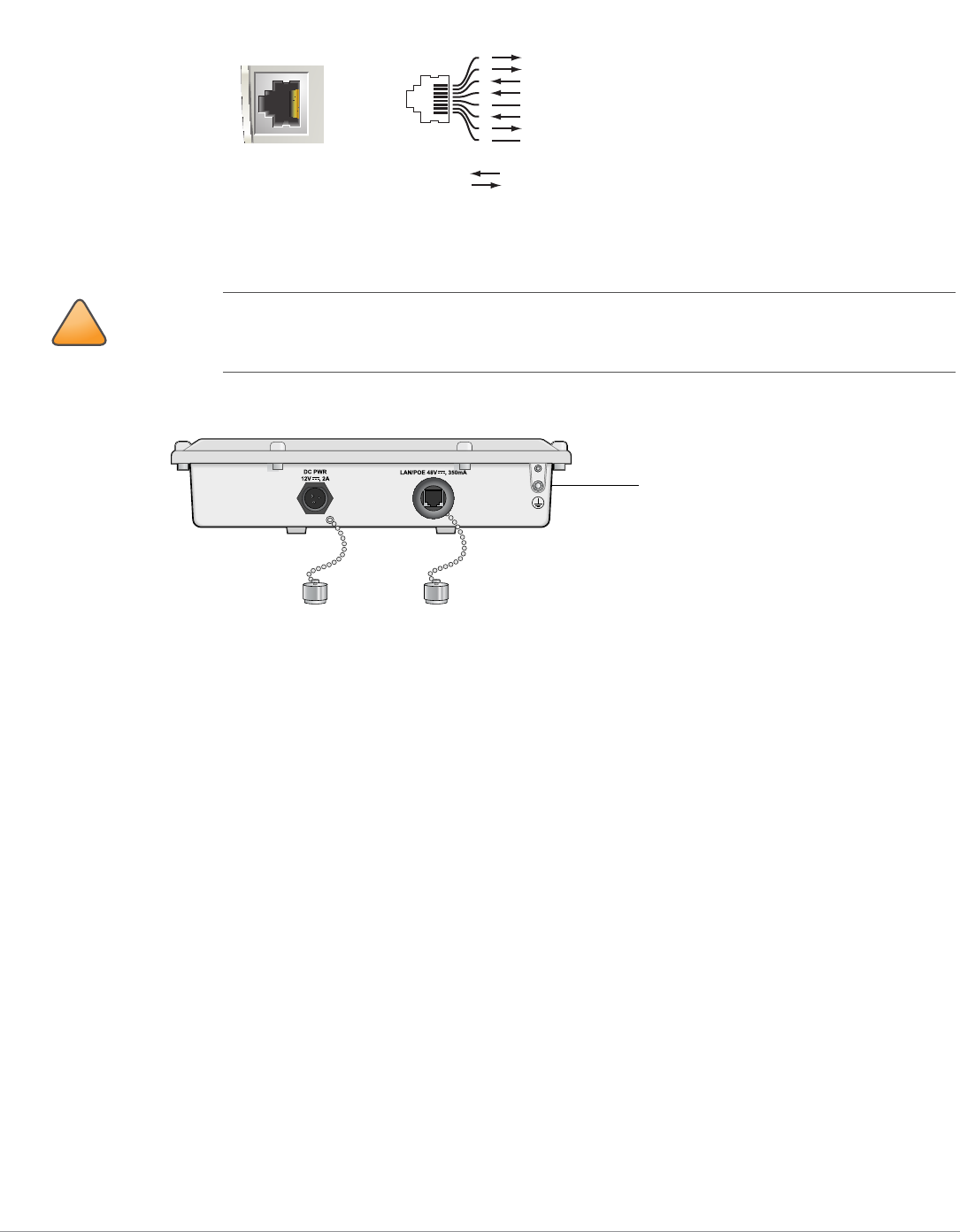
Figure 4 10/100Base-T Fast Ethernet (RJ-45) Port Pin-Out
zGrounding Point
Figure 5 AP-85TX Bottom View
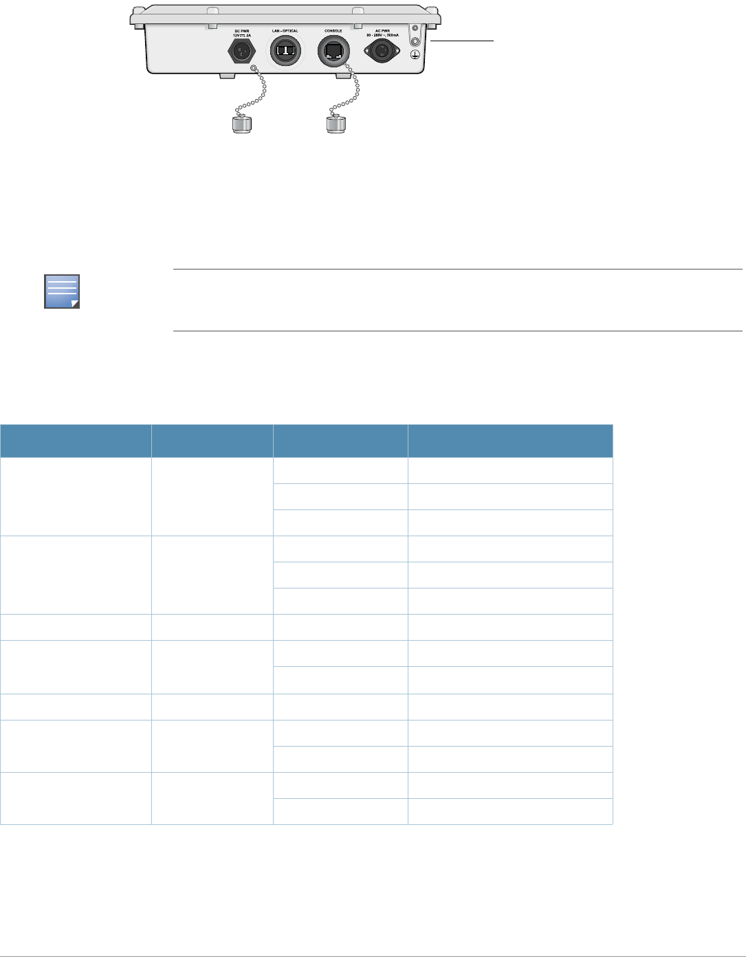
AP-85FX/LX Bottom View
The bottom of the AP-85FX/LX unit (see Figure 5) has the following ports and connections:
zDC PWR 12 VDC, 2 A: The AP can accept DC power in the range of 8 to 16 VDC. If the AP-85FX/LX is not connected to an
AC power source, the AP must be powered by a DC power source. An outdoor rated, two-wire, 8-foot long DC power
cable (wiring harness) is supplied with the unit. For proper installation instructions, see "DC and AC Power Cables" on
page30.
zLAN - OPTICAL:
AP-85FX: This model has a 100BASE-FX data uplink port for multi-mode, dual-fiber network connectivity. A multi-
mode, fiber patch cable with a duplex LC connector is required for use. The cable is not included and must be
purchased separately.
AP-85LX: This model has a 100BASE-LX data uplink port for single-mode, dual-fiber network connectivity. A single-
mode, fiber patch cable with a duplex LC connector is required for use. The cable is not included and must be
purchased separately.
zCONSOLE: A serial console port is provided for connection to a terminal, allowing direct local management.
!
CAUTION
It is important that the AP-85TX be properly grounded and a grounding point is provided on the
bottom of the AP-85TX model. A professional installer should ensure that grounding is available and
meets applicable local and national electrical codes.
AP-85
10/100Base-T
Fast Ethernet (RJ-45)
RJ-45 Female
Pin-Out
*POE optional
**Serial optional
Serial RxD**
Serial RGND** (POE positive*)
Serial TxD**
Serial TGND** (POE negative*)
1
2
3
4
5
6
7
8
ETH Tx+ (POE negative*)
ETH Tx– (POE negative*)
ETH Rx+ (POE positive*)
ETH Rx– (POE positive*)
Direction
Input
Output
Grounding Point
12 | AP-85 Series Hardware Overview Aruba AP-85 Outdoor Access Point Series | Installation Guide
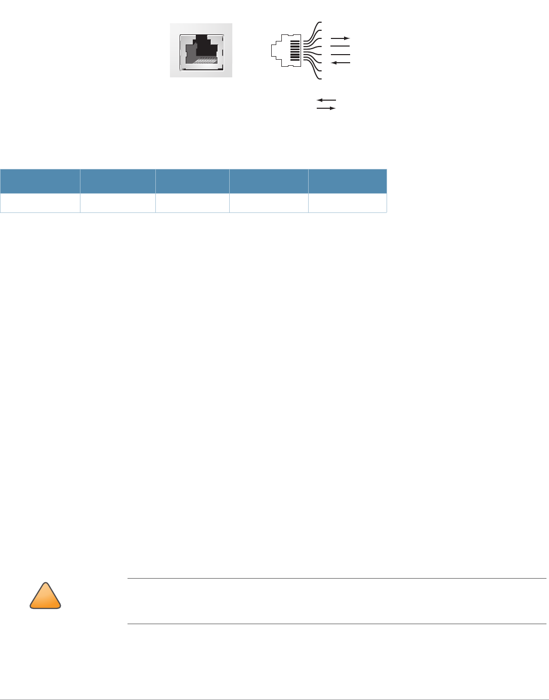
Figure 6 Serial Console Port Pin-Out
Communication settings for the serial console port are listed in Table 1.
zAC PWR 90-228 V~, 500 mA: The AP can accept AC power at the limits specified on the unit. If the AP-85FX/LX is not
connected to a DC power source, the AP must be powered by an AC power source. An outdoor rated, three-wire, 8-foot
long AC power cable (wiring harness) is supplied with the unit. Some installation locations are in the scope and under
the authority of the National Electric Code (NEC or NFPA 70), and some are not, as indicated in Article 90.2. The NEC
applies where:
The product must be grounded reliably using the external screw, as shown in this installation guide, and not solely
depend on the ground provided in the power supply cord.
The power cord should be less than 15" long.
The plug for the power cord should be installed in a dry location, such as with the use of an NRTL listed receptacle
box with cover that is weatherproof with the power plug inserted into the receptacle (such as the MultiMac model
from Taymac Corp).
The NEC does not apply when:
The installation must follow all regulations and established practices that are applicable for the particular installation
environment.
For international outdoor use:
The product must be grounded reliably using the external screw, as shown in this installation guide, and not solely
depend on the ground provided in the power supply cord. Considerations should include selection of weatherproofing
means (IP67 or better), proper strain relieving for the power cord, and adherence to all applicable regulations and
local practices.
The plug for the power cord should be installed in a dry location, such as with the use of a suitable certified
receptacle box with a cover, which is weatherproof (IP67 or better) with the power plug inserted into the receptacle.
zGrounding Point
.
Table 1 Console Terminal Settings
Baud Rate Data Bits Parity Stop Bits Flow Control
9600 8 None 1 None
!
CAUTION
It is important that the AP-85FX/LX be properly grounded; a grounding point is provided on the
bottom of the AP-85FX/LX model. The installer (trained service personnel) should ensure that
grounding is available and that the grounding meets applicable local and national electrical codes.
Serial
Console Port
1
2
3
4
5
6
7
8
TxD
GND
RxD
RJ-45 Female
Pin-Out
Direction
Input
Output
GND
Aruba AP-85 Outdoor Access Point Series | Installation Guide AP-85 Series Hardware Overview | 13
Figure 7 AP-85FX/LX Bottom View
LED Status Indicators
All AP-85 models include visual indicators for power, link, and radio status. Additionally, each radio has a seven-LED array
that indicates received signal strength (RSSI).
Table 2 lists the meanings of the LEDs on the AP-85 outdoor access points.
NOTE
The RSSI LED indicators represent varying degrees in the RSSI level. The absence of a signal is
indicated by no LED response, and full signal strength is indicated when all seven LEDs are active
and lit.
Table 2 AP-85 LED Status Indicators
LED Function Indicator Status
PWR AP Power/Ready
Status
Off No power to AP
Flashing Device booting, not ready
On Device ready
LINK/ACT
(applicable to the
AP-85TX only)
LAN/Network Link
Status
Off Ethernet link unavailable
On (Yellow) 10 Mbs Ethernet link negotiated
On (Green) 100 Mbs Ethernet link negotiated
Blinking Traffic on Ethernet link
LINK/ACT
(applicable to the
AP-85FX/LX models only)
LAN/Network Link
Status
Off Ethernet link unavailable
On (Green) 100 Mbs Ethernet link negotiated
Blinking Traffic on Ethernet link
RADIO 0 Radio 0 Status Off Radio 0 disabled
On (Green) Radio 0 enabled in WLAN mode
RADIO 1 Radio 1 Status Off Radio 1disabled
On (Green) Radio 1 enabled in WLAN mode
Grounding Point

14 | AP-85 Series Hardware Overview Aruba AP-85 Outdoor Access Point Series | Installation Guide
Optional Accessories
The following items are available for use with AP-85 outdoor access points and are sold separately. Contact your Aruba sales
representative for details and assistance.
zAruba 85 Field Replaceable Mount Kit: P/N AP-85-MNT-S
zAruba 85 Low-Profile Wall Mount Bracket: P/N AP-85-MNT-2
zAruba 85 Streetlight Power Tap Adapter (8 ft): P/N AP-85-PT-1
zAruba 85 AC Power Provisioning Cable (3 ft; indoor rated): P/N AP-85-CBL-1
zAruba 85 Antenna Mount Bracket: P/N AP-85-MNT-1
zAruba 85 AC Power Cable (8 ft): P/N AP-85-CBL-2-US-S or AP-85-CBL-2-EU-S
zAruba 85 AC Power Cable (40 ft): P/N AP-85-CBL-3-US-S or AP-85-CBL-3-EU-S
zAruba 85 DC Power Cable (8 ft): P/N AP-85-CBL-4-S
zAruba Lightning Arrester: P/N AP-LAR-1
RSSI (Radio 0) RSSI Level for
Radio 0
Off RSSI disabled/no signal
7 Step Progressive
Bars
3/6/9/12/15/21/27 dB
RSSI
Each bar represents a progressive
increase in signal strength, with 7
bars representing maximum signal
strength (100%).
Minimum data rate: Two lit LEDs
Maximum data rate: Six lit LEDs
RSSI (Radio 1) RSSI Level for
Radio 1
Off RSSI disabled/no signal
7 Step Progressive
Bars
3/6/9/12/15/21/27 dB
RSSI
Each bar represents a progressive
increase in signal strength, with 7
bars representing maximum signal
strength (100%).
Minimum data rate: Two lit LEDs
Maximum data rate: Six lit LEDs
NOTE
AC power cables are available for use with the AP-85FX/LX models only.
Table 2 AP-85 LED Status Indicators (Continued)
LED Function Indicator Status

Aruba AP-85 Outdoor Access Point Series | Installation Guide Outdoor Planning and Deployment Considerations | 15
Chapter 2
Outdoor Planning and
Deployment Considerations
Planning and Deployment Considerations
Prior to deploying an outdoor wireless network, the environment must be evaluated to plan for a successful Aruba WLAN
deployment. Successfully evaluating the environment enables the proper selection of Aruba APs and antennas and assists in
the determination of their placement for optimal RF coverage. This process is considered WLAN or RF planning and Aruba’s
system engineers can assist in the outdoor planning process.
Scale Requirements
The potentially immense scale of outdoor deployments requires consideration of factors that may not be as important in a
typical indoor deployment:
zRange (distance): Range or distance between APs must be taken into account during the planning phase. Available AP
mounting locations are often far less flexible in an outdoor environment. Regardless of these outdoor restrictions, the
desired goal is to achieve results similar to an indoor deployment: a “dense” RF deployment that supports advanced
Aruba features, such as ARM, efficient client roaming, and failover.
zElevation: Proper consideration and planning for elevation differences between APs (AP to AP) and AP to Client can be
critical to success. To plan for these differences in elevation, it is important to understand the 3D coverage pattern
provided by the antennas that will be deployed in the environment.
zNon-Fixed Considerations: The RF environment might change on a day to day basis. Keep non-fixed items, such as
shipping containers, vehicles, and future building construction, in mind when planning for an outdoor deployment.
Identifying Known RF Absorbers/Reflectors/Interferences Sources
Identifying known RF absorbers/reflectors/interference sources while out in the field during the installation phase is critical.
Even though outdoor environments consist of fewer RF absorbers/reflectors/interference sources compared to indoor
environments, ensure that these sources are identified and taken into consideration when installing and mounting an AP to
its fixed outdoor location.
RF Absorbers
zCement/Concrete
zNatural Items: Trees/vegetation
zBrick
RF Reflectors
zMetal Objects: Roof-installed air-conditioning equipment, chain link fences (depending on aperture size), other wire
fences, or water pipes
16 | Outdoor Planning and Deployment Considerations Aruba AP-85 Outdoor Access Point Series | Installation Guide
RF Interference Sources
zOther 802.11a/b/g or broadband access equipment operating nearby
zIndustrial RF welding equipment or other Industrial, Scientific and Medical (ISM) equipment that utilizes RF to heat or
alter the physical properties of materials
zMilitary, Commercial Aviation or Weather Radar Systems
Line of Sight (Radio Path Planning)
AP-85 Series access points are capable of performing as one of the following:
zEnterprise mesh point (MP)
zEnterprise mesh portal (MPP)
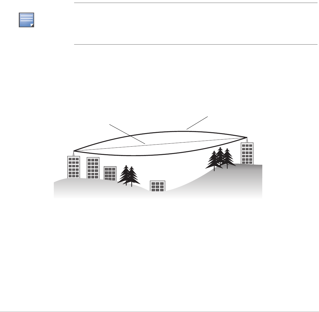
A wireless bridge or mesh link requires a “radio line of sight” between the two antennas for optimum performance. The
concept of radio line of sight involves the area along a link through which the bulk of the radio signal power travels. This
area is known as the first Fresnel Zone of the radio link. For a radio link, no object (including the ground) must intrude
within 60% of the first Fresnel Zone.
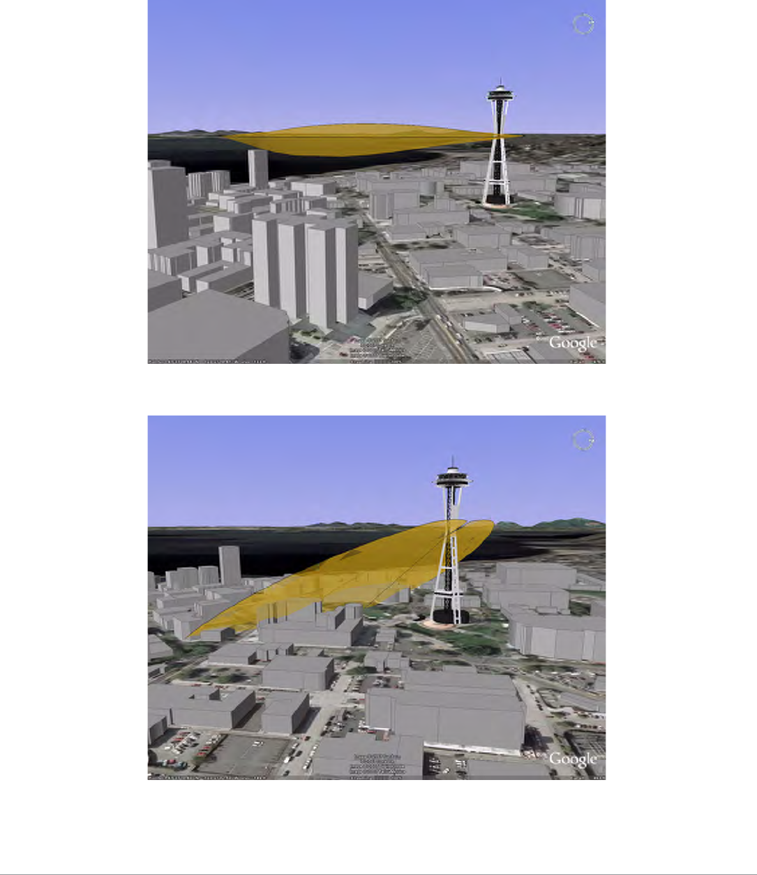
Figure 8 illustrates the concept of a good radio line of sight.
Figure 8 Line of Sight
If there are obstacles in the radio path, there may still be a radio link but the quality and strength of the signal will be
affected. Calculating the maximum clearance from objects on a path is important as it directly affects the decision on
antenna placement and height. It is especially critical for long-distance links, where the radio signal could easily be lost.
When planning the radio path for a wireless bridge or mesh link, consider these factors:
zAvoid any partial line of sight between the antennas
zBe cautious of trees or other foliage that may be near the path, or may grow and obstruct the path.
zBe sure there is enough clearance from buildings and that no building construction may eventually block the path.
zFor very long distance links, the curvature of the earth (20 cm per km) may need to be considered in the calculation of
relative heights.
NOTE
To configure the AP-85 as a mesh point or mesh portal, you must install a mesh software license on
a Mobility Controller as a software license key. Contact your sales account manager or authorized
reseller to obtain the software license. There are several mesh software licenses available that
support different maximum number of APs. The licenses are cumulative; each additional license
installed increases the number of APs (mesh nodes) supported by the Mobility Controller.
Radio Line of Sight
Visual Line of Sight
Aruba AP-85 Outdoor Access Point Series | Installation Guide Outdoor Planning and Deployment Considerations | 17
zCheck the topology of the land between the antennas using topographical maps, aerial photos, or even satellite image
data (software packages are available that may include this information for your area)
zAvoid a path that may incur temporary blockage due to the movement of cars, trains, or aircraft.
Antenna Height
A reliable wireless bridge or mesh link is usually best achieved by mounting the antennas at each end high enough for a clear
radio line of sight between them. The minimum height required depends on the distance of the link, obstacles that may be in
the path, topology of the terrain, and the curvature of the earth (for links over 3 miles).
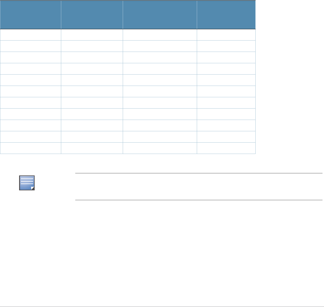
For long-distance links, the AP may have to be mounted on masts or poles that are tall enough to attain the minimum
required clearance. Use the following table to estimate the required minimum clearance above the ground or path
obstruction (for 5 GHz bridge links).
Table 3 Antenna Minimum Height and Clearance Requirements
Total Link Distance
Max Clearance for
60% of First Fresnel
Zone at 5.8 GHz
Approximate Clearance
for Earth Curvature
Total Clearance
Required at
Mid-point of Link
0.25 mile (0.402 km) 4.6 ft (1.4 m) 0.007 ft (0.002 m) 4.6 ft (1.4 m)
0.5 mile (0.805 km) 6.2 ft (1.9 m) 0.03 ft (0.010 m) 6.2 ft (1.9 m)
1 mile (1.6 km) 8.9 ft (2.7 m) 0.13 ft (0.04 m) 8.9 ft (2.7 m)
2 miles (3.2 km) 12.5 ft (3.8 m) 0.5 ft (0.15 m) 13.1 ft (4.0 m)
3 miles (4.8 km) 15.4 ft (4.7 m) 1.0 ft (0.3 m) 16.4 ft (5.0 m)
4 miles (6.4 km) 17.7 ft (5.4 m) 2.0 ft (0.6 m) 19.7 ft (6.0 m)
5 miles (8 km) 20 ft (6.1 m) 3.0 ft (0.9 m) 23 ft (7.0 m)
7 miles (11.3 km) 23.6 ft (7.2 m) 6.2 ft (1.9 m) 30 ft (9.1 m)
9 miles (14.5 km) 27 ft (8.2 m) 10.2 ft (3.1 m) 37 ft (11.3 m)
12 miles (19.3 km) 30.8 ft (9.4 m) 18.0 ft (5.5 m) 49 ft (14.9 m)
15 miles (24.1 km) 34.4 ft (10.5 m) 28.0 ft (8.5 m) 62.7 ft (19.1 m)
NOTE
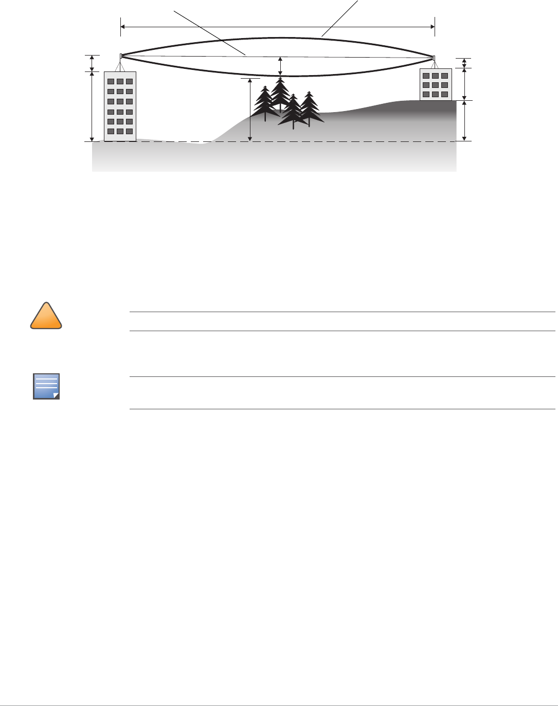
To avoid any obstruction along the path, the height of the object must be added to the minimum
clearance required for a clear radio line of sight. Consider the following simple example, illustrated in
Figure 9.
18 | Outdoor Planning and Deployment Considerations Aruba AP-85 Outdoor Access Point Series | Installation Guide
Figure 9 Antenna Height and Line of Sight
A wireless bridge or mesh link is deployed to connect building A to building B, which is located three miles (4.8 km) away.
Mid-way between the two buildings is a small tree-covered hill. From the above table it can be seen that for a three-mile link,
the object clearance required at the mid-point is 5.3 m (17.4 ft). The tree tops on the hill are at an elevation of 17 m (56 ft), so
the antennas at each end of the link need to be at least 22.3 m (73 ft) high. Building A is six stories high, or 20 m (66 ft), so a
2.3 m (7.5 ft) mast or pole must be constructed on its roof to achieve the required antenna height. Building B is only three
stories high, or 9 m (30 ft), but is located at an elevation that is 12 m (39 ft) higher than building A. To mount an antenna at
the required height on building B, a mast or pole of 1.3 m (4.3 ft) is needed.
Antenna Position and Orientation
Once the required antenna height has been determined, other factors affecting the precise position of the wireless bridge or
mesh link must be considered:
zBe sure there are no other radio antennas within 2 m (6 ft) of the wireless bridge or mesh link. These include other WiFi
radio antennas.
zPlace the wireless bridge or mesh link away from power and telephone lines.
zAvoid placing the wireless bridge or mesh link too close to any metallic reflective surfaces, such as roof-installed air-
conditioning equipment, tinted windows, wire fences, or water pipes. Ensure that there is at least 5 feet clearance from
such objects.
zThe wireless bridge or mesh link antennas at both ends of the link must be positioned with the same polarization
direction, either horizontal or vertical. Proper alignment helps to maximize throughput.
!
CAUTION
Never construct a radio mast, pole, or tower near overhead power lines.
NOTE
Local regulations may limit or prevent construction of a high radio mast or tower. If your wireless
bridge or mesh link requires a high radio mast or tower, consult a professional contractor for advice.
AB
3 miles (4.8 km)
5.4 m
17 m
20 m
2.4 m
12 m
9m
1.4 m
Radio Line of Sight
Visual Line of Sight

Aruba AP-85 Outdoor Access Point Series | Installation Guide Outdoor Planning and Deployment Considerations | 19
Radio Interference
The avoidance of radio interference is an important part of wireless link planning. Interference is caused by other radio
transmissions using the same or an adjacent channel frequency. You should first scan your proposed site using a spectrum
analyzer to determine if there are any strong radio signals using the 802.11a/b/g channel frequencies. Always use a channel
frequency that is furthest away from another signal.
If radio interference is still a problem with your wireless bridge or mesh link, changing the antenna direction may improve
the situation.
Weather Conditions
When planning wireless bridge or mesh links, you must take into account any extreme weather conditions that are known to
affect your location. Consider these factors:
zTemperature: The wireless bridge or mesh link is tested for normal operation in temperatures from
-. Operating in temperatures outside of this range may cause the unit to fail
zWind Velocity: The wireless bridge or mesh link can operate in winds up to. You must consider the known maximum
wind velocity and direction at the site and be sure that any supporting structure, such as a pole, mast, or tower, is built to
withstand this force.
zLightning: Rain: The wireless bridge or mesh link is weatherproofed against rain. However, it is recommended to apply
weatherproof sealing tape around the Ethernet port and antenna connectors for extra protection. If moisture enters a
connector, it may cause a degradation in performance or even a complete failure of the link.
zSnow and Ice: Falling snow, like rain, has no significant effect on the radio signal. However, a buildup of snow or ice on
antennas may cause the link to fail. In this case, the snow or ice has to be cleared from the antennas to restore operation
of the link.
Ethernet Cabling
When a suitable antenna location has been determined, you must plan a cable route from the wireless bridge or mesh link
outdoors to a suitable power and/or network source.
Consider these points:
zThe Ethernet cable length should never be longer than 90 m (295 ft).
zDetermine a building entry point for the cable (if applicable).
zDetermine if conduits, bracing, or other structures are required for safety or protection of the cable.
zFor lightning protection at the power injector end of the cable, consider using a lightning arrestor immediately before the
cable enters the building
Grounding
It is important that the wireless bridge or mesh link, cables, and any supporting structures are properly grounded. Each AP-
85 Series access point includes a grounding screw for attaching a ground wire. Be sure that grounding is available and that it
meets local and national electrical codes. Ground the access point first using the external ground stud on the unit before
making any other connection.
!
CAUTION
An Aruba Lightning Arrestor, AP-LAR-1, must be installed on each antenna port for protection
against lightning induced surges. Failure to use an AP-LAR-1 can void the warranty of an Aruba
outdoor AP model and renders the AP susceptible to failure from lightning induced surges.

20 | Outdoor Planning and Deployment Considerations Aruba AP-85 Outdoor Access Point Series | Installation Guide

Aruba AP-85 Outdoor Access Point Series | Installation Guide AP-85 Series Installation | 21
Chapter 3
AP-85 Series Installation
Pre-Installation Network Setup
When WLAN planning is complete and the appropriate products and their placement have been determined, the Aruba
Mobility Controller(s) must be installed and initial setup performed before the Aruba Outdoor Access Points. are deployed.
For initial setup of the Mobility Controller, refer to the ArubaOS Quick Start Guide for the software version installed on
your controller.
Pre-Installation Checklist
Before installing your AP-85, be sure that you have the items listed in Table 4.
Access Point Setup
Successful setup of an AP-85 consists of five tasks, which must be performed in the following order:
1. Verify pre-installation connectivity
2. Provision the AP-85
3. Install the AP-85
4. Verify post-installation connectivity
5. Configure the AP-85
Table 4 AP-85 Pre-Installation Checklist
AP-85TX AP-85FX/LX
zFast Ethernet (FE) cable of required length
zIEEE 802.3af compliant PoE source (Aruba
Mobility Controller or Midspan device) or DC
power source
zAruba Mobility Controller configured and
installed on the network
zLayer 2/3 network connectivity to your AP-85
zOne of the following network services:
1. Aruba Discovery Protocol (ADP)
2. DNS server with an “A” record
3. DHCP Server with vendor specific options
zFiber patch cable of required length:
1. Single-mode fiber patch cable for the AP-85LX
2. Multi-mode fiber patch cable for the AP-85FX
zAC or DC power source
zAruba Mobility Controller configured and installed
on the network
zLayer 2/3 network connectivity to your AP-85
zOne of the following network services:
1. Aruba Discovery Protocol (ADP)
2. DNS server with an “A” record
3. DHCP Server with vendor specific options
NOTE
It is important that you follow the guidelines in the previous section, "Pre-Installation Network
Setup" on page21, before attempting to set up and install an AP-85.
22 | AP-85 Series Installation Aruba AP-85 Outdoor Access Point Series | Installation Guide
Verifying Pre-Installation Connectivity
Before you install APs in a network environment, make sure that the APs will be able to locate and connect to the Mobility
Controller when they are powered on.
Specifically, you must verify the following conditions:
zWhen connected to the network, each AP is assigned a valid IP address.
zAPs can locate the Mobility Controller (Mobility ControllerDiscovery).
Refer to the ArubaOS Quick Start Guide for instructions on locating and connecting to the Mobility Controller.
Provisioning the AP
Each AP has unique provisioning parameters. These local AP parameters are initially configured on the Mobility Controller.
The Mobility Controller pushes the parameters out to the specific AP, where they are stored. Aruba recommends that you
configure the provisioning settings using the ArubaOS Web UI only. Refer to the ArubaOS User Guide for complete details.
Installing the AP-85
NOTE
Aruba Networks, in compliance with governmental requirements, has designed the AP-85 such that
only authorized network administrators can change configuration settings. For more information
about AP configuration, refer to the ArubaOS Quick Start Guide and ArubaOS User Guide.
!
CAUTION
Access points are radio transmission devices and as such are subject to governmental regulation.
Network administrators responsible for the configuration and operation of access points must
comply with local broadcast regulations. Specifically, access points must use channel assignments
appropriate to the location in which the access point will be used.
NOTE
If the AP-85 is to be deployed in a mesh networking environment, the AP-85 must be provisioned as
a mesh portal or a mesh point before deployment.
!
CAUTION
RF Radiation Exposure Statement: This equipment complies with FCC RF radiation exposure limits.
This equipment should be installed and operated with a minimum distance of 13.8 inches (35 cm)
between the radiator and your body for 2.4 GHz and 5 GHz operations. This transmitter must not be
co-located or operating in conjunction with any other antenna or transmitter.
!
CAUTION
Aruba Access Points, AP-LAR-1 lightning arresters, and cable termination kits must be installed by
trained service personnel. These installers are responsible for ensuring that grounding is available
and that grounding meets applicable local and national electrical codes.
Aruba AP-85 Outdoor Access Point Series | Installation Guide AP-85 Series Installation | 23
Mounting the AP-85
Preparing the AP-85 for Installation
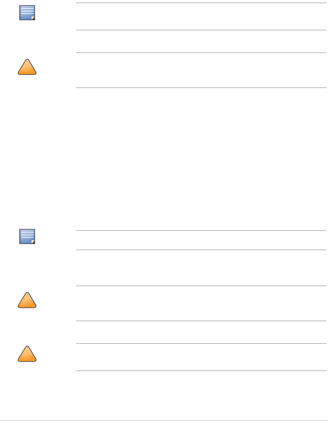
1. Install the provided mounting bolts (M8 bolts with captive flat washer) into the four mounting holes on the rear of the
AP-85 (see Figure 10). Leave approximately two to three threads showing on each mounting bolt.
Figure 10 Installing the Mounting Bolts
Wall Mounting the AP-85
To wall mount an AP-85:
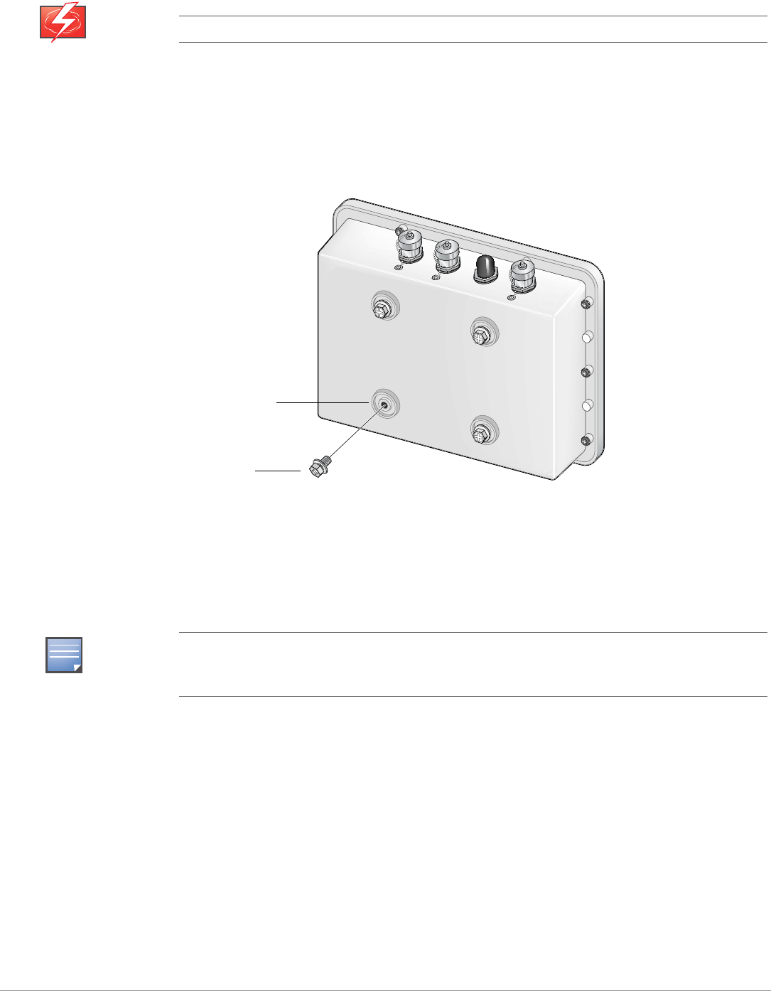
1. Secure the mounting plate to a flat wall using the appropriate screws and anchors for your mounting application (see
Figure 11).
WARNING
Do not work on an AP and do not connect or disconnect cables during periods of lightning activity.
NOTE
Wall mount hardware is not included with the mounting plate and must be purchased separately for
your mounting application. The mounting plate accepts the following screw or bolt sizes: M4, M5,
SAE #8, and SAE #10.
Mounting Holes
Mounting Bolts
(M8 bolts, 4x)
24 | AP-85 Series Installation Aruba AP-85 Outdoor Access Point Series | Installation Guide
Figure 11 Attaching the Mounting Plate
2. Seat the AP-85 into the four keyholes on the mounting plate and tighten down the four mounting bolts (M8 bolts) to
secure the AP-85 in place (see Figure 12). The mounting plate should rest between the captive flat washer on each
mounting bolt and the rear of the AP-85.
Figure 12 Wall Mounting the AP-85
Pole Mounting the AP-85 (1.5-inch to 3.5-inch Diameter)
To attach an AP-85 to a pole with a diameter of 1.5 inches to 3.5 inches:
1. Assemble the pole mounting bracket:
a. Slide the long T-bolt through the opening in the mounting bracket (see Figure 13).
b. Attach the provided retaining clip to the T-bolt (see Figure 13).
c. Screw the provided nut onto the end of the T-bolt (see Figure 13).
NOTE
Figure 12 shows the AP-85 installed with the antenna jacks at the top of the unit. To install the AP-
85 with the antenna jacks at the side, rotate the unit 90 degrees before seating the unit on the
mounting plate.
Anchors (4x)
Mounting Plate
Screws (4x)
Wall
arun_0127A
Mounting Bolts
Mounting Plate
AP-85
Wall
Aruba AP-85 Outdoor Access Point Series | Installation Guide AP-85 Series Installation | 25
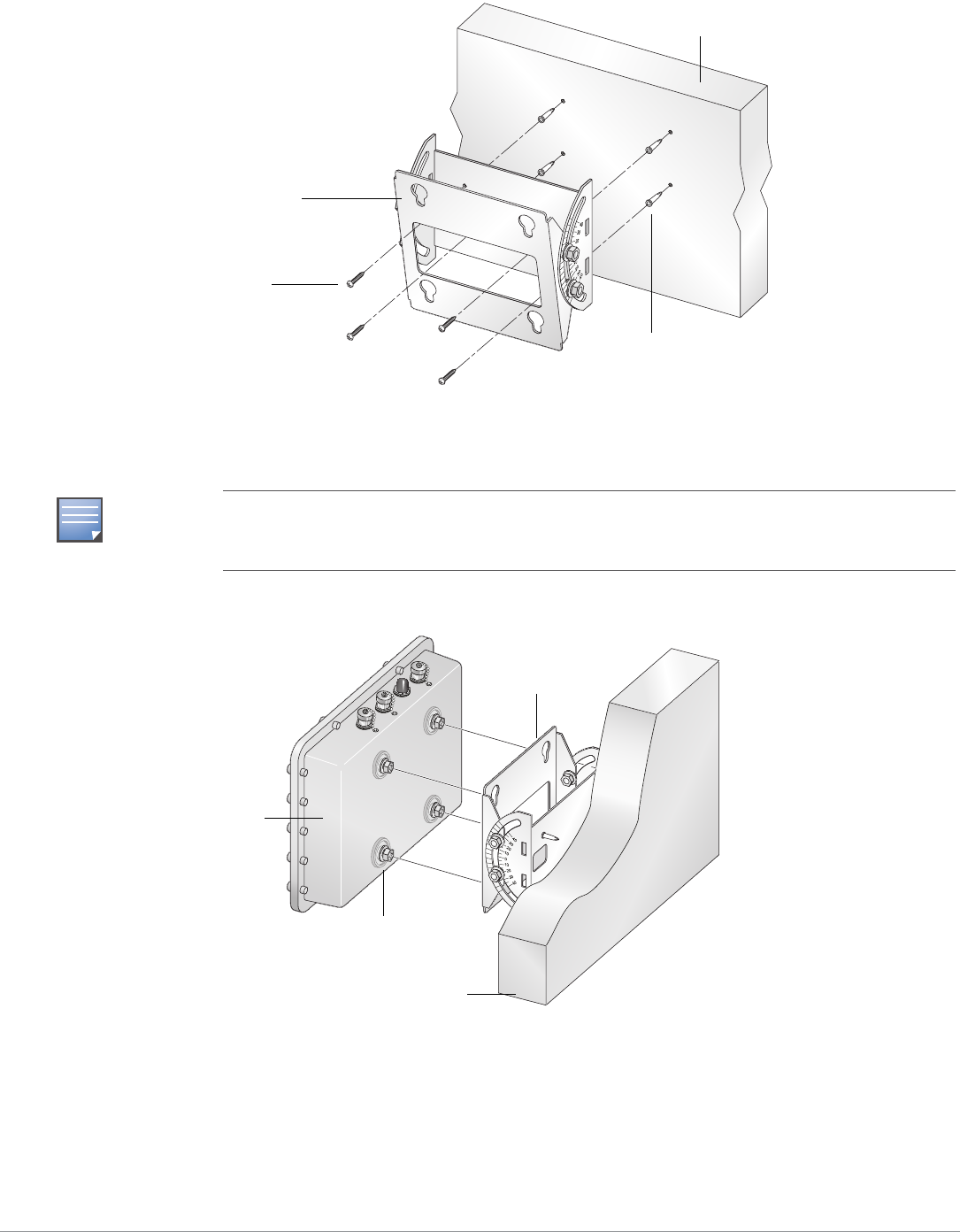
2. Secure the mounting plate to the mounting bracket using the four provided Phillips screws (see Figure 13).
Figure 13 Assembling the Pole Mounting Bracket
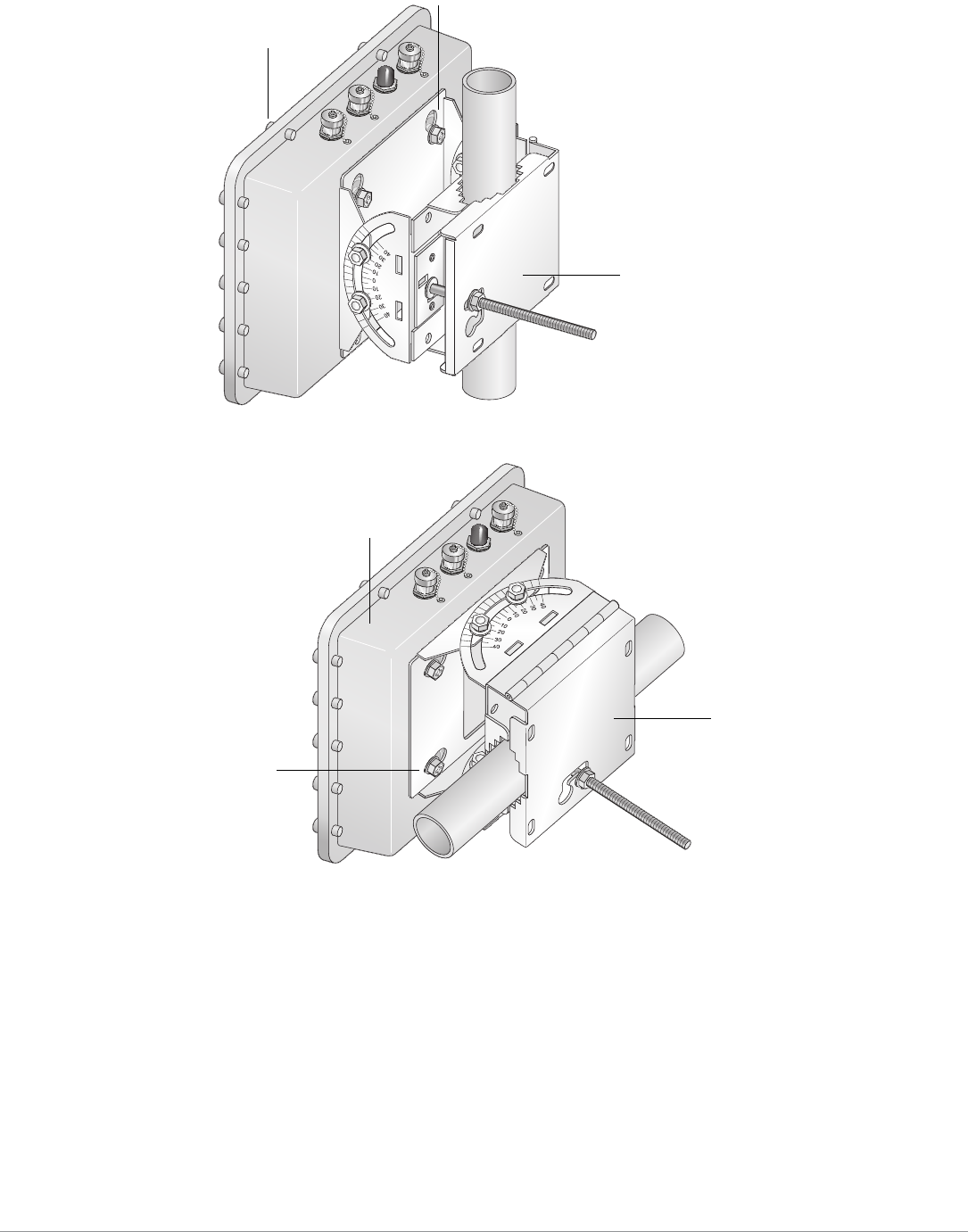
3. Attach the pole mounting bracket assembly to a 1.5-inch to 3.5-inch diameter pole and secure the bracket in place (see
Figure 14).
a. Wrap the pole mounting bracket around the pole.
b. Slip the end of the T-bolt with nut through the opening in the pole mounting bracket.
c. Maneuver the T-bolt to the top slot in the pole mounting bracket and tighten down the nut. Verify that the nut is tightly
secured and that the bracket cannot move. It must be secure to support the weight of the AP-85.
Figure 14 Attaching the Pole Mounting Bracket
4. Seat the AP-85 into the four keyholes on the mounting plate and tighten the four mounting bolts (M8 bolts) to secure the
AP-85 in place (see Figure 15 and Figure 16). The mounting plate should rest between the captive flat washer on each
mounting bolt and the rear of the AP-85.
NOTE
The pole mounting bracket can be secured to a horizontal or vertical pole. The position of the
keyholes on the mounting plate allows you to mount the AP-85 on either pole type with the antenna
jacks at the top or the side. To mount the AP-85 with the antenna jacks at the side, rotate the unit 90
degrees before seating the unit on the mounting plate.
arun_0137
Nut (1x)T-Bolt (1x)
Phillips Screws (4x)
Mounting Bracket
Mounting Plate
Retaining Clip
arun_0129
arun_0130
arun_0130
Step A Step C
Step B
26 | AP-85 Series Installation Aruba AP-85 Outdoor Access Point Series | Installation Guide
Figure 15 Vertical Pole Mount Position (1.5-inch to 3.5-inch Diameter Pole)
Figure 16 Horizontal Pole Mount Position (1.5-inch to 3.5-inch Diameter Pole)
Pole Mounting the AP-85 (Pole Diameter Greater than 3.5-inches)
To attach an AP-85 to a pole with a diameter greater than 3.5 inches:
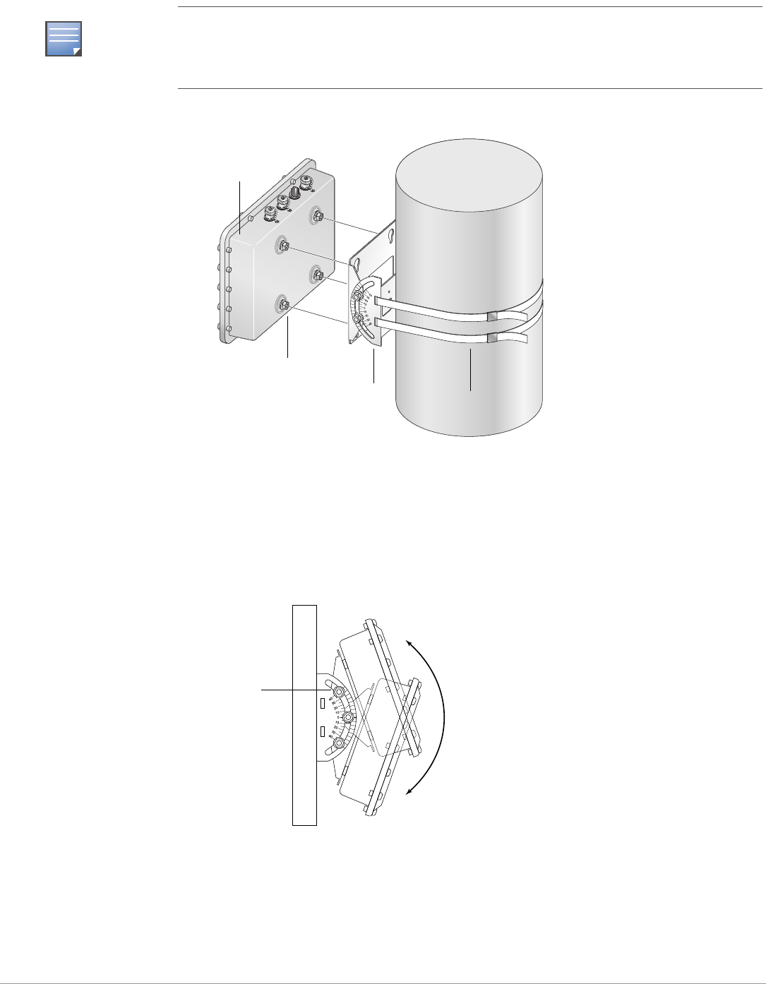
1. Attach the mounting plate to the pole using outdoor rated straps (see Figure 17). Outdoor rated straps are not included
with the unit and must be purchased separately.
2. Seat the AP-85 into the four keyholes on the mounting plate and tighten down the four mounting bolts (M8 bolts) to
secure the AP-85 in place (see Figure 17). The mounting plate should rest between the captive flat washer on each
mounting bolt and the rear of the AP-85.
arun_0131B
Secured
Mounting Bracket
Tightened Mounting Bolts
AP-85
arun_0131C
Secured
Mounting Bracket
Tightened Mounting
Bolts
AP-85
Aruba AP-85 Outdoor Access Point Series | Installation Guide AP-85 Series Installation | 27
Figure 17 Pole Mounting the AP-85 (Diameter Greater than 3.5 Inches)
Positioning the AP-85
To adjust the angle of an AP-85 on a vertical pole:
1. Loosen the four M8 bolts on the side of the mounting plate. Rotate the AP to the desired angle and tighten down the M8
bolts (see Figure 18).
Figure 18 Positioning the AP-85 on a Vertical Pole
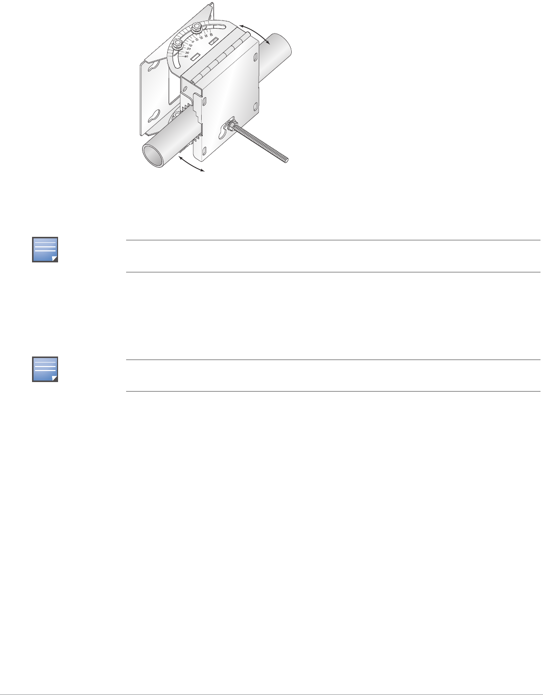
To adjust the angle of an AP-85 on a horizontal pole:
1. Rotate the entire mounting bracket to the desired angle and tighten the bracket into place (see Figure 19).
NOTE
The mounting plate can be secured to a horizontal or vertical pole. The position of the keyholes on
the mounting plate allows you to mount the AP-85 on either pole type with the antenna jacks at the
top or the side. To mount the AP-85 with the antenna jacks at the side, rotate the unit 90 degrees
before seating the unit on the mounting plate.
arun_0135A
Outdoor-Rated Straps
Mounting Plate
Mounting Bolts
AP-85
M8 Positioning Bolts
(4x, 2x per side)
28 | AP-85 Series Installation Aruba AP-85 Outdoor Access Point Series | Installation Guide
Figure 19 Positioning the AP-85 on a Horizontal Pole
Connecting Required Cables
RJ-45 CAT 5 Cable
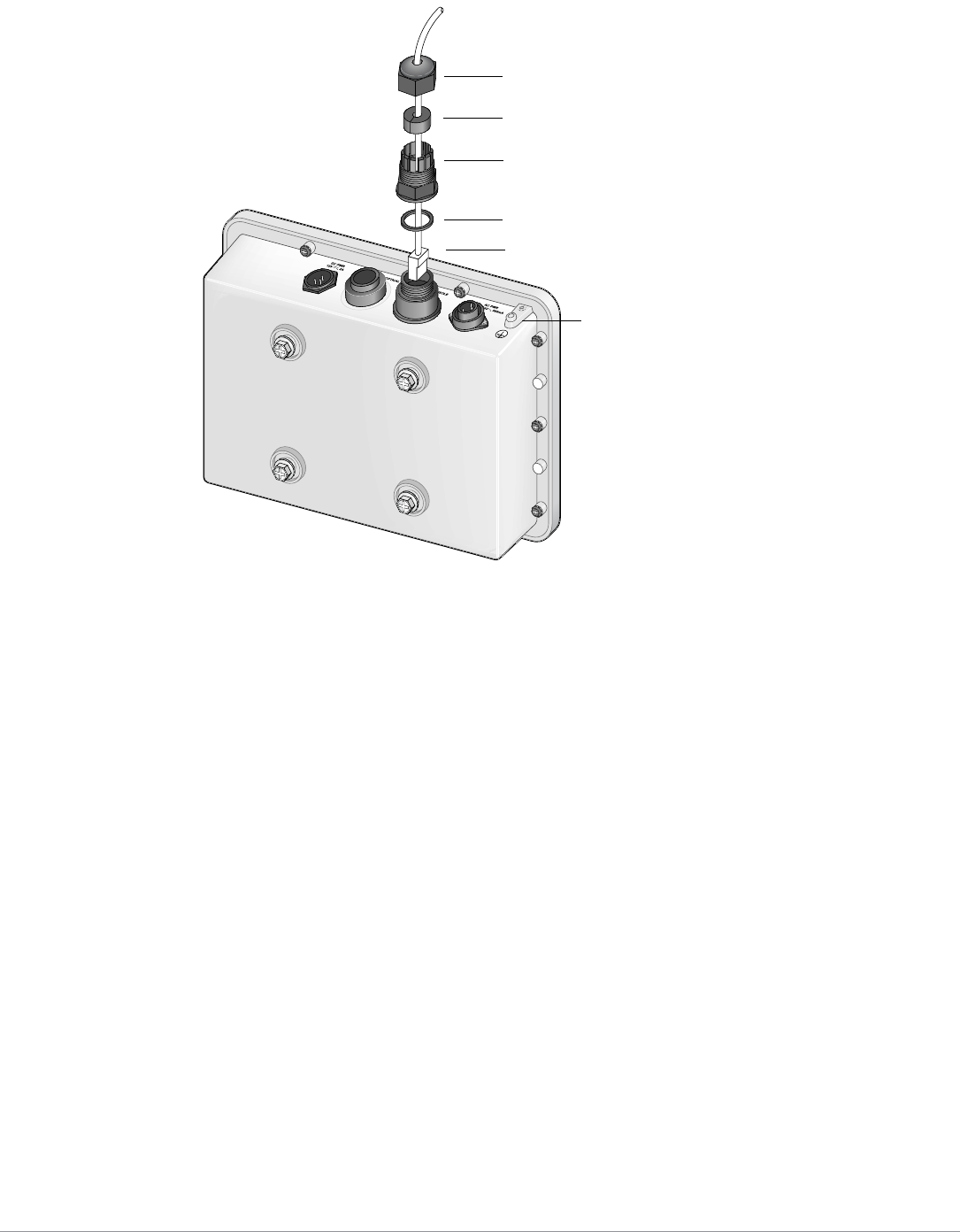
To weatherproof and connect an RJ-45 terminated CAT 5E or better cable to an AP-85 (see Figure 20), perform the following
using the contents in the included kit that ships with your unit:
1. Slide the cap over the terminated cable.
2. Slide the rubber grommet over the terminated cable.
3. Slide the connector shell over the terminated cable.
4. Slide the washer over the terminated cable.
5. Insert the rubber grommet into the top of the connector shell until the top surface of the grommet is flush with the top
edge of the connector shell.
6. Connect the terminated cable to the proper port: LAN/POE port on the AP-85TX model or the CONSOLE port on the AP-
85FX/LX models.
7. Screw the connector shell onto the interface on the AP-85.
8. Screw the cap onto the connector shell.
NOTE
Before connecting other cables, first connect the ground stud to ground reference. See Figure 20 for
the location of the ground stud.
NOTE
The cable is not included and must be purchased separately. Purchase a suitable UV-resistant,
outdoor rated, CAT 5E or better RJ-45 cable for use with the AP-85.
arun_0131D
Aruba AP-85 Outdoor Access Point Series | Installation Guide AP-85 Series Installation | 29
Figure 20 Weatherproofing and Connecting an RJ-45 Terminated CAT 5 Cable
arun_0127
Cap
Rubber Grommet
Connector Shell
Washer
Terminated CAT 5E or Better Cable
Ground Stud
30 | AP-85 Series Installation Aruba AP-85 Outdoor Access Point Series | Installation Guide
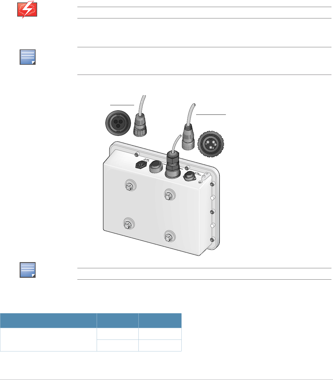
DC and AC Power Cables
To connect the power cables (wiring harnesses):
1. Screw the two-wire, 8-foot long DC power cable (wiring harness) to the DC interface on the AP-85TX, AP-85FX, or AP-
85LX model.
2. Screw the three-wire, 8-foot long AC power cable (wiring harness) to the AC interface on the AP-85FX or AP-85LX
models only.
Figure 21 Connecting Power
WARNING
Disconnect the AC mains before handling the AC power cable and connecting it to the AP-85.
NOTE
All connections made to the unit should conform to all local and national electrical codes. Power
cords with lengths longer than 15 ft and cords without plugs should only be installed in appropriate
areas. Check the codes for your area to ensure proper use.
NOTE
Always shut power off to the unit to de-energize it before disconnecting any cables.
Table 5 AC and DC Power Cable Descriptions
Cable Type Wire Color Assignment
DC Power Cable Red +12V
Black Ground
DC Power Cable
AC Power Cable
Aruba AP-85 Outdoor Access Point Series | Installation Guide AP-85 Series Installation | 31
Fiber Optic Cable
To use the fiber optic termination kit that is shipped with the AP-85FX/LX models, follow the instructions in the included
Tyco document Instruction Sheet 408-10079.
Aruba provides a multi-language document containing country specific restrictions and additional safety and regulatory
information for all Aruba hardware products. This document can be viewed or downloaded from the following location:
www.arubanetworks.com/safety_addendum.
This product complies with 21 CFR Chapter 1, Subchapter J, Part 1040.10, and IEC 60825-1: 1993, A1: 1997, A2: 2001, IEC
60825-2: 2000.
For continued compliance with the above laser safety standards, only approved Class 1 modules from our approved vendors
should be installed in Aruba products.
Lightning Arrestor Installation
Refer to the instructions that are shipped with the Aruba lightning arrestor (AP-LAR-1).
Antenna Installation
Refer to the instructions that are shipped with your Aruba outdoor rated antenna.
AC Power Cable: United States (US) Black Line
White Neutral
Green Ground
AC Power Cable: Europe (EU) Brown Line
Blue Neutral
Green/Yellow Ground
NOTE
Fiber optic cables are not included and must be purchased separately. Purchase a suitable UV-
resistant, outdoor rated, multi-mode fiber optic cable for use with the AP-85FX and a single-mode
fiber optic cable for use with the AP-85LX.
!
CAUTION
Use of controls or adjustments of performance or procedures other than those specified in this
manual may result in hazardous radiation exposure.
Table 5 AC and DC Power Cable Descriptions
Cable Type Wire Color Assignment
CLASS 1
LASER PRODUCT

32 | AP-85 Series Installation Aruba AP-85 Outdoor Access Point Series | Installation Guide
Verifying Post-Installation Connectivity
The LEDs on the AP-85 can be used after installation to verify that the AP is receiving power, that the AP is initializing
successfully, and that wireless connectivity is occurring (see "LED Status Indicators" on page13). Refer to the ArubaOS
Quick Start Guide for further details on verifying post-installation network connectivity.
Configuring the AP-85
Configuration parameters are network or controller specific and are configured and stored on the Mobility Controller.
Network configuration settings are pushed out to the AP(s) but remain stored on the Mobility Controller. Configuration
settings can be configured via the ArubaOS Web UI, ArubaOS CLI, or Aruba MMS. Refer to their respective guides for further
details: the ArubaOS User Guide or Aruba Mobility Management System User Guide.
Aruba AP-85 Outdoor Access Point Series | Installation Guide Understanding Antennas | 33
Appendix A
Understanding Antennas
Aruba Antennas
Before you can select the antenna type needed for the deployment, read the basic wireless antenna information provided in
this section. This information will help you understand wireless antenna basics and Aruba antenna specifications.
Understanding Wireless Antennas
Omni-Directional vs. Directional Coverage
For optimal performance of your wireless network, it is essential to understand the purpose behind proper antenna
selection. Choosing the correct antenna type will ensure that RF energy is being directed to the correct coverage areas.
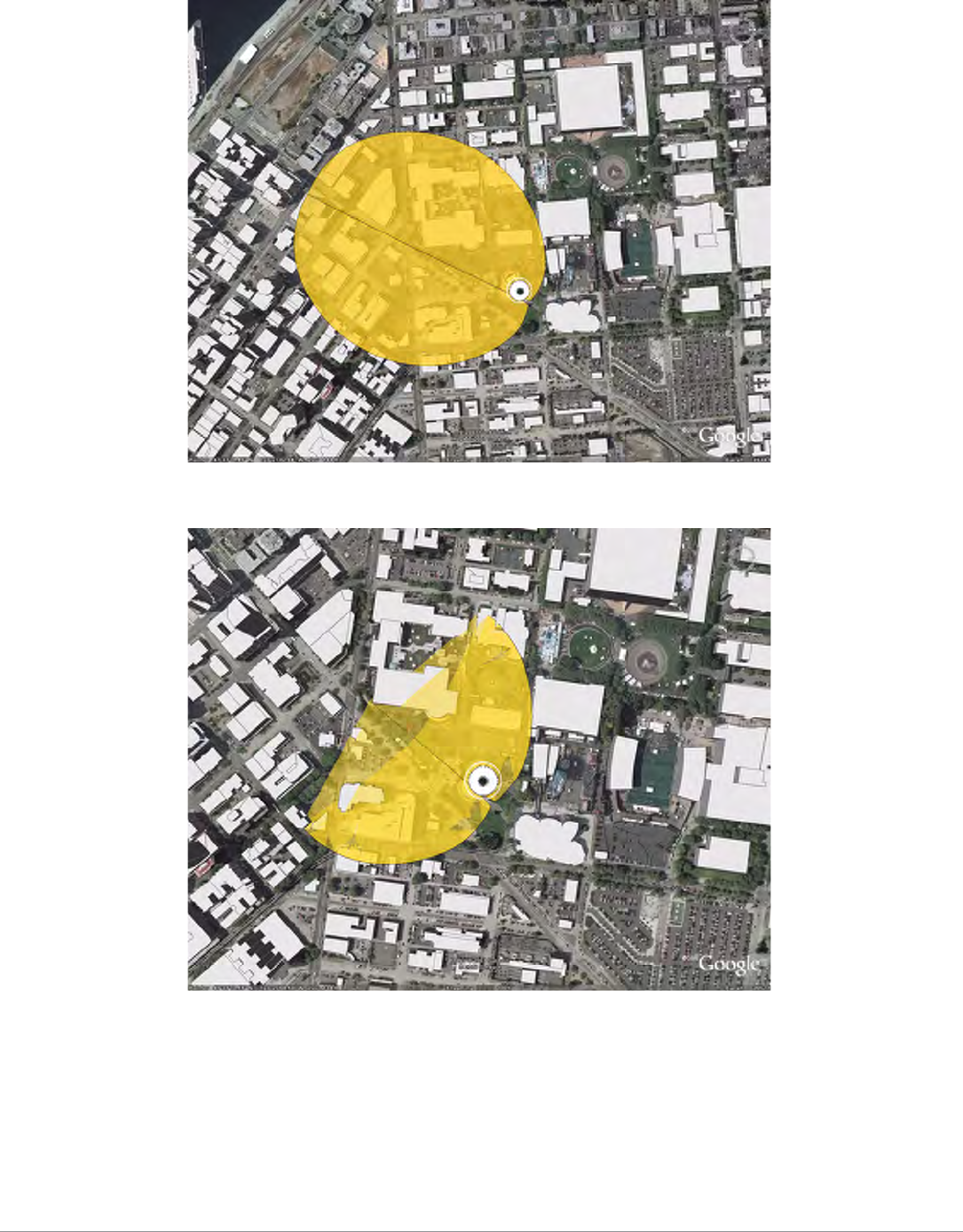
Omni-directional antennas provide equal coverage in all directions (see Figure 22), while directional antennas point RF
energy in a specific direction for RF concentration within a targeted area (see Figure 23).
Figure 22 Omni-Directional Antenna
Figure 23 Directional Antenna
Antenna Location
Area of Coverage
Direction of Coverage
Antenna Location
Area of Coverage
Direction of Coverage
34 | Understanding Antennas Aruba AP-85 Outdoor Access Point Series | Installation Guide
Antenna Beamwidth, Pattern, and Gain Considerations
Antenna gain is a relative measure of how the antenna compares to an ideal isotropic radiator. An ideal, isotropic radiator
would radiate power in all directions equally over a sphere. The relationship between gain, power, and propagation distance
is detailed already in textbooks and Wiki's, so these expressions are not repeated here. Antenna gain is often confused with
power gain in amplifiers, but it is important to note that antenna gain only makes a transmitter's power appear to be higher
than would be predicted by calculation of the power fed to the antenna and then spread equally over a sphere. Antenna gain
itself is a completely passive and bi-directional property, determined only by the shape and construction of the antenna.
Knowing that gain is only a comparison of the apparent power to the power that would be required if fed to an ideal isotropic
antenna, you realize that gain can only be created by distorting the antenna pattern from the ideal spherical pattern. Think of
this as focusing the same power that would normally distribute evenly over a sphere into a tighter region of space. Thus, the
higher the gain, the more concentrated (in some way) the antenna pattern must be in order to achieve that gain.
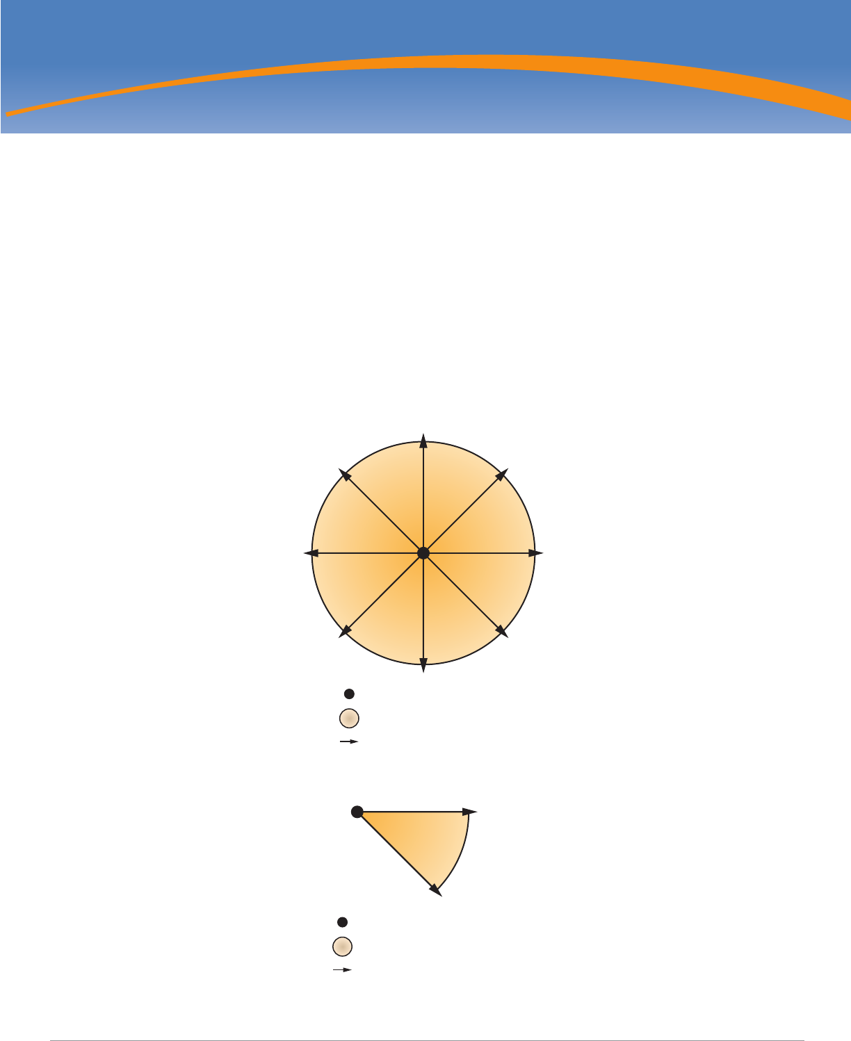
Example
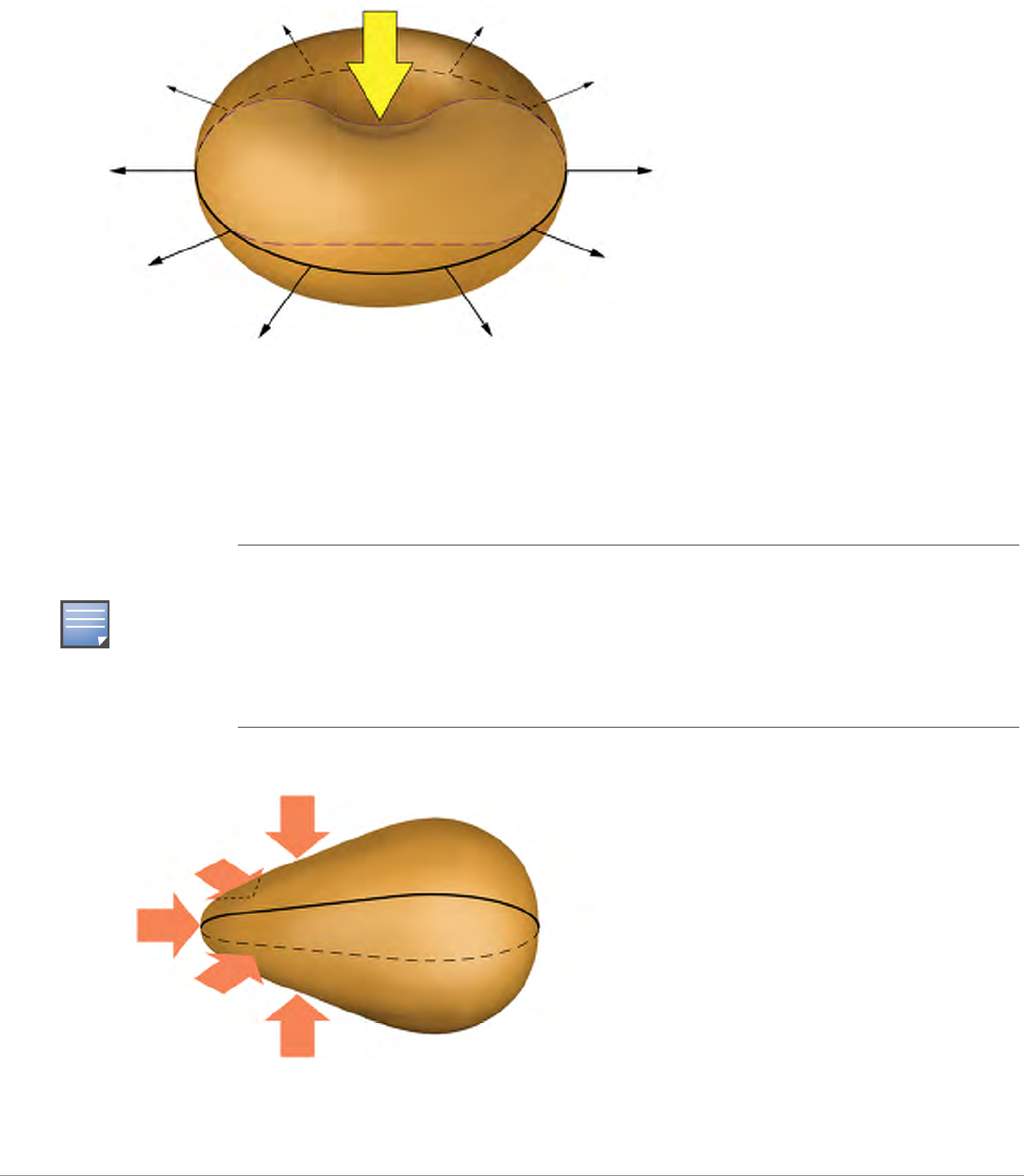
To visualize the concept of gain, picture a rubber ball. The surface area of the ball represents the total available power
radiated by an ideal isotropic antenna over its sphere of radiation (see Figure 24).
Figure 24 Equal Signal Strength Radiated in All Directions
Equal Signal Strength
Radiated over a Sphere
Aruba AP-85 Outdoor Access Point Series | Installation Guide Understanding Antennas | 35
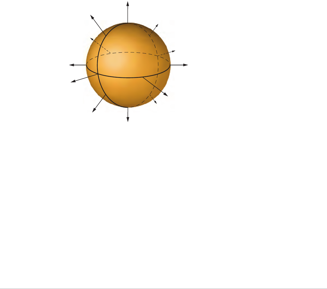
Now, still using the same ball with the same available surface area, how would you be able to stretch the ball farther out?
One way is to press down on the top of the ball and squash it down vertically. This would keep the same basic shape in the
horizontal plane (round), but it would force the ball to stretch, creating a pancake shape, in the vertical direction (see Figure
25). This represents the concept of the high gain omni-directional antenna, which achieves a greater coverage distance in the
horizontal direction at the expense of coverage in the vertical areas of the radiating sphere.
Figure 25 High Gain Omni-Directional Antenna
To stretch the ball primarily in one direction (instead of in all directions), push the ball, both vertically and horizontally, on
the sides and on the back, to force the ball to deform in a single direction. This action would significantly distort the shape of
the original ball both horizontally and vertically, but it will allow you to stretch the same ball a lot farther in one direction
(see Figure 26). This represents the concept of the high gain directional antenna, which is designed to compress the entire
radiating sphere into a single predominate direction.
Figure 26 High Gain Directional Antenna
NOTE
Gain is created by forcing transmitted power to radiate in a preferred direction rather than radiating
in all directions of an ideal sphere. Therefore, a high gain signal is always accompanied by loss of
available signal in some other portion of the ideal sphere. High gain directional antennas are ideal for
sites requiring directed coverage in a specific area or extended range for bridging applications, but
they are not suited for sites requiring uniform coverage in large areas. It is important to keep in mind
that both vertical and horizontal coverage can be affected by the use of a higher gain antenna and
beamwidth (a measure of coverage) is always inversely related to gain.
High Gain
Omni-Directional Antenna
Compressed vertical signal,
which expands signal
horizontally
High Gain Directional Antenna
Entire sphere compressed into a
single predominate direction, focusing
RF energy to a targeted area of
coverage
36 | Understanding Antennas Aruba AP-85 Outdoor Access Point Series | Installation Guide
Understanding Antenna Pattern Plots and Specifications
Traditional 2-D pattern plots and beamwidth specifications are like mental puzzles waiting to be solved because they only
provide a snapshot of the information in two planes. These two planes are often referred to as the azimuth (H-plane or
horizontal) and elevation (vertical or E-plane) planes. The azimuth view would be considered the view from directly above,
viewing the antenna pattern on the horizontal plane. The elevation view is considered to be a side view, viewing the antenna
pattern on the vertical plane. It is helpful to think of these planes as “cuts” of the real antenna pattern, which is actually 3-D.
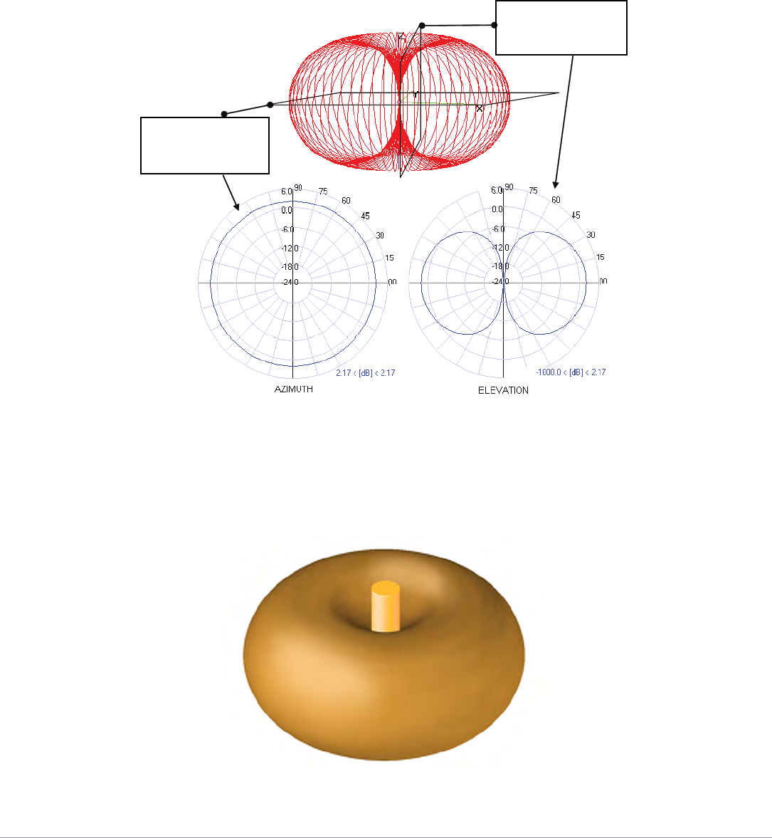
Figure 27 illustrates where these “cuts” are located for a typical omni-directional antenna pattern.
Figure 27 Antenna Pattern Conventions (Omni-Directional Pattern Shown)
The antenna illustrated by Figure 27 is commonly referred to as the dipole pattern because it is the pattern produced by an
ideal dipole antenna. The gain of this antenna is 2.14, which is achieved by compression in the vertical plane (elevation)
compared to the ideal sphere. If referring to the true 3D pattern, this compression is sometimes called the donut shape (see
Figure 28).
Figure 28 Donut Shape Compression of an Omni-Directional Antenna
Azimuth, H-plane,
or Horizontal
Pattern Diagram
Elevation, E-plane,
or Vertical Pattern
Diagram

Aruba AP-85 Outdoor Access Point Series | Installation Guide Understanding Antennas | 37
It is evident from Figure 27 that 2-D pattern plots typically provided in antenna specifications are a simplification of the real
3-D situation. Often, 2-D plots are reduced even further to a set of simple specifications based on the antenna gain and 3 dB
beamwidth.
Detachable Antenna Selection
Select the correct antenna type to support the required frequency band (2.4 GHz or 5 GHz) and desired coverage pattern.
To select the correct antenna type for the deployment, download and read Aruba’s outdoor antenna specifications: http://
www.arubanetworks.com/products/access-points/antennas.php.
Detachable Outdoor Antenna Types
These are some of the terms used to describe Aruba’s detachable antenna offerings. Terminology and degree of sector in
Aruba’s antenna specifications are determined by the horizontal 3 dB beamwidth.
zDown-Tilt: An omni-directional antenna that focuses its energy downwards.
zSector/Patch: A directional antenna that provides a focused sector of coverage from a central point (Example: +/- 45
degrees from a 90 degree center point).
zPanel: A flat formed antenna that directs energy to a sector of coverage. This type of antenna is often ideal for point-to-
point WDS bridging or wireless mesh backhaul applications.
Detachable Antenna Selection Tips
zIf omni-directional coverage is desired with the greatest possible horizontal range from the AP, select one of Aruba's
detachable antennas with high-gain, omni-directional coverage. Due to the tight vertical beamwidth of high-gain, omni-
directional antennas, this typically requires mounting the antenna not more than 5 meters (16.5 feet) above the expected
client locations in elevation.
zIf omni-directional coverage is desired, but only high mounting locations are available
(approx. 5 m (16.5 feet) to 10 m (33 feet), consider the use of lower gain (3 dBi to 5 dBi) omni-directional antennas and a
denser AP deployment. The lower gain antenna will reduce the maximum horizontal range of the AP, but will provide
better vertical coverage.
zFor very high mounting locations (>10 m/33 feet) such as light poles or monopoles, consider the use of an omni-
directional antenna with electrical downtilt. A downtilt omni-directional antenna is an antennas that has a direction of
maximum gain at approximately 45° down from horizontal.
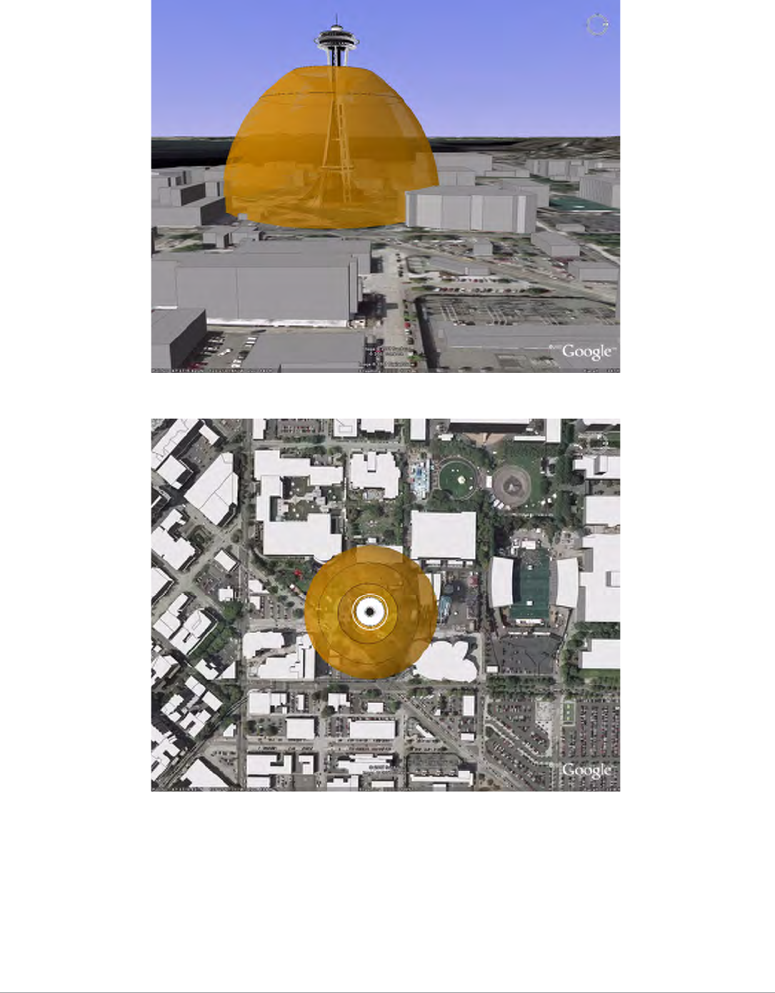
NOTE
All figures are shown with a 100 meter (328 feet) mounting height above the ground and for a
18 Mbps coverage area.
38 | Understanding Antennas Aruba AP-85 Outdoor Access Point Series | Installation Guide
Figure 29 AP-ANT-90 E-Plane View (Side View)
Figure 30 AP-ANT-90 H-Plane View (Top View)
zAlternatively, for high mounting locations, high-gain sector antennas may be used with mechanical downtilt. This will
typically require the use of multiple access points per mounting location to provide omni-directional coverage.
zIf a directional antenna is required to direct RF coverage, the detachable antenna must be capable of supporting all of the
frequency bands that require support (2.4 GHz and/or 5 GHz).
zDirectional antennas are selected to focus RF energy more efficiently to a targeted area.
zDirectional antennas are also useful in areas where the surrounding materials have high amounts of RF attenuation or
reflection and the RF signal needs to be guided in the direction of the least amount of attenuation or reflection. For
Aruba AP-85 Outdoor Access Point Series | Installation Guide Understanding Antennas | 39
example, when mounting antennas on the outside surfaces of a building to provide coverage to outdoor spaces in front of
the building, a directional antenna can be used to direct the coverage away from the building.
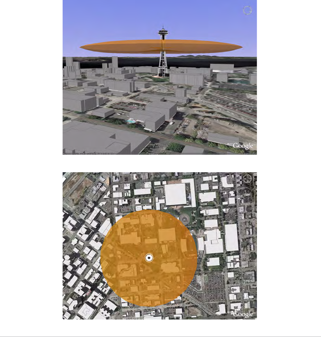
High Mounting Omni-Directional Antenna Scenario (AP-ANT-80 vs. AP-ANT-90)
The AP-ANT-80 shows greater horizontal range due to its higher gain (8 dBi vs. 3 dBi) antenna, but in this very high mounting
situation, the AP-ANT-90 may be a better choice for ground level coverage because the direction of maximum gain is
directed downward toward the ground. This situation could potentially be improved if a lower mounting elevation was
available for the AP-ANT-80, ideally about
5 m above Ground.
Figure 31 AP-ANT-80 E-Plane View (Side View)
Figure 32 AP-ANT-80 H-Plane View (Top View)
40 | Understanding Antennas Aruba AP-85 Outdoor Access Point Series | Installation Guide
High Mounting Directional Antenna Scenario
The AP-ANT-82 is a high gain (12 dBi), directional antenna with a 90 degree 3 dB beamwidth in azimuth. For this high
mounting condition, this antenna provides a long range in the direction of maximum gain, but it would require mechanical
downtilt for ground level coverage.
Figure 33 AP-ANT-82 E-Plane View (Side View)
Figure 34 AP-ANT-82 with 30 Degree Downtilt E-Plane View (Side View)
Aruba AP-85 Outdoor Access Point Series | Installation Guide Understanding Antennas | 41
Figure 35 AP-ANT-82 H-Plane View (Top View)
Figure 36 AP-ANT-82 with 30 Degree Downtilt H-Plane View (Top View)

42 | Understanding Antennas Aruba AP-85 Outdoor Access Point Series | Installation Guide

Aruba AP-85 Outdoor Access Point Series | Installation Guide Product Specifications | 43
Appendix B
Product Specifications
Product Specifications
Mechanical (AP-85TX, AP-85FX, and AP-85LX)
zDevice Dimensions (HxWxD):
10.80” x 12.64” x 3.07”
274 mm x 321 mm x 78 mm
zDevice Weight: 7.40 lbs/3.36 kgs
zDevice Weight with Mounting Plate: 9.65 lbs/4.38 kgs
zDevice Weight with Mounting Plate and Mounting Bracket: 10.85 lbs/4.92 kgs
zIP68 (1 m depth for 8 hrs) under IEC 60529 NEMA type 4X
zTemperature:
Operating: -30ºC to 55ºC (-22ºF to 131ºF)
Storage: -40ºC to 70ºC (-40ºF to 158ºF)
zRelative Humidity: 0% to 95% non-condensing
zAltitude: 0-3000 m (0-9850 ft)
zSurvival Wind Speed: 125 mph (201 km/hr)
zMounting:
Articulating adjustable pole or mast mount kit (included)
Antenna mount bracket (optional)
zAntenna: Quad, N-type Female interfaces for external antenna support
zGround: Electrical safety/ground terminal point
zVisual Status Indicators (LEDs):
Onboard LED array for RSSI level reading
PWR - Power/Status
LINK/ACT - LAN/Network Link Status
RADIO 0 - Radio 0 Status
RADIO 1 - Radio 1 Status
RSSI (Radio 0) - RSSI Level for Radio 0
RSSI (Radio 1) - RSSI Level for Radio 1
Electrical
AP-85TX
z1 x 10/100 Base-T auto-sensing Ethernet (RJ-45) Interface
IEEE 802.3 BaseT and 802.3u 100BaseTX compliant
PoE 48V DC Power over Ethernet (IEEE 802.3af compliant)
Serial over Ethernet (SoE)

44 | Product Specifications Aruba AP-85 Outdoor Access Point Series | Installation Guide
Auto-sensing MDI/MDX
z1 x 12 V DC / up to 2.0 A power interface (for external solar supplied DC power)
z1 x Electrical Ground / Safety Terminal
zFully environmentally hardened connector types (all interfaces)
AP-85FX
z1 x 100BASE-FX data uplink port for multi-mode, dual-fiber connectivity
1310 nm wavelength, 2 km over MMF Interface
LC fiber optic connector type
z1 x 12 V DC up to 2.0 A power interface (for external solar supplied DC power)
z1 x 90-228 V~ / 500 mA auto-sensing power interface with transient power surge suppression
z1 x Serial Console Port
z1 x Electrical Ground / Safety Terminal
zFully environmentally hardened connector types (all interfaces)
AP-85LX
z1 x 100BASE-LX data uplink port for single-mode, dual-fiber connectivity
1310 nm wavelength, 10km over SMF
LC fiber optic connector type
z1 x 12 V DC up to 2.0 A power interface (for external solar supplied DC power)
z1 x 90-228 V~ / 500 mA auto-sensing power interface with transient power surge suppression
z1 x Serial Console Port
z1 x Electrical Ground / Safety Terminal
zFully environmentally hardened connector types (all interfaces)
Maximum Power Draw
zThe 12 V DC input power source should be SELV (non-shock hazardous (<30 V DC) under normal and single fault
conditions) and limited power source (LPS) as a non-fire-hazardous circuit as defined in IEC 60950-1, or a Class Z power
source as defined by the NEC.
zIT power system: Models AP-85FX and AP-85LX are designed for connection to TN or IT power distribution systems.
Wireless LAN
zNetwork Standards - IEEE 802.11b, IEEE 802.11g and IEEE 802.11a
zAntenna Type - None. Detachable, outdoor rated, 2.4 or 5 GHz antenna options available
zRadio Technology:
802.11a/g - Orthogonal Frequency Division Multiplexing (OFDM)
Table 6 AP-85 Series Maximum Power Draw
AP Model Power Source Measurement
Condition
Max Current
(Amps)
Max Power
(Watts)
AP-85TX PoE 48 V 0.25 12
AP-85TX, AP-85FX, AP-85LX DC 12 V 0.8 9.6
AP-85FX, AP-85LX AC 240 V, 60 Hz 0.18 (RMS) 20.14

Aruba AP-85 Outdoor Access Point Series | Installation Guide Product Specifications | 45
802.11b - Direct Sequence Spread Spectrum (DSSS)
zRadio Modulation Type:
802.11a - BPSK, QPSK,16-QAM, 64-QAM
802.11b - DQPSK/CCK, DQPSK, DBPSK
802.11g - OFDM, DQPSK/CCK, DQPSK, DBPSK
zMedia Access Control - CSMA/CA with ACK
zData Rates:
802.11a - 6, 9, 12, 18, 24, 36, 48 and 54 Mbps per channel
802.11b - 1, 2, 5.5, 11 Mbps per channel
802.11g - 1, 2, 5.5, 6, 9, 11, 12, 22, 24, 33, 36 and 54 Mbps per channel
zTransmit and Available Channels: Determined by country of use and Aruba certifications within country of use
Safety and Regulatory Compliance
Aruba provides a multi-language document containing country specific restrictions and additional safety and regulatory
information for all Aruba hardware products. This document can be viewed or downloaded from the following location:
www.arubanetworks.com/safety_addendum.
Declaration of Conformity
Aruba Networks, Inc., 1322 Crossman Avenue, Sunnyvale, CA 94089, USA, declares that the Aruba Wireless Access Point,
Model: AP-85 conforms to the following European directives:
zR&TTE Directive 99/5/EC
zWEEE Directive 2002/96/EC
zRoHS Directive 2002/95/EC
zATEX Directive 94/9/EC
R&TTE Directive relevant standards:
zArticle 3.2; EN 300 328v1.7.1 and, EN 301 893 v1.4.1
zArticle 3.1b; EN 301 489-17 v1.2.1
zArticle 3.1a; EN 60950-1, EN60950-22
ATEX Directive standard:
zEN60079-0:2004, EN60079-15:2005
Year Mark first applied: 2008
I, the undersigned, hereby declare that the equipment specified above conforms to the above Directives and Standards.
!
CAUTION
Aruba Access Points and the AP-LAR-1 lightning arrestor are required to be installed by a
professional installer. The professional installer is responsible for ensuring that grounding is
available and it meets applicable local and national electrical codes.
WARNING
Do not work on an AP and do not connect or disconnect cables during periods of lightning activity.
46 | Product Specifications Aruba AP-85 Outdoor Access Point Series | Installation Guide
European Headquarters
77 Oxford Street
London, W1D 2ES
United Kingdom
Phone: +44 20 7659 2024
Fax: +44 20 7043 5871
Contact: Albert Benhamou
info-emea@arubanetworks.com
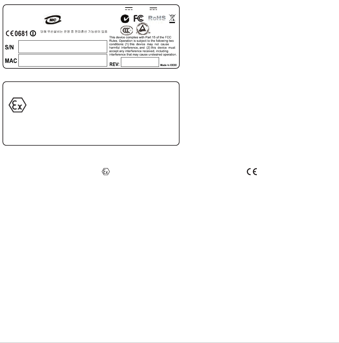
Instructions for Use in a Potentially Explosive Atmosphere
Type of Protection: II 3 G Ex nA T6 ; ignition protection category “n”
Enclosure: NEMA Type 4X, IP67
Applicable Standards: IEC 60079-0:2004
EN 60079-0:2004
IEC 60079-15:2005
EN 60079-15:2005
ARU-AP85TX N19592
FCC ID: Q9DAP85
IC: 4675A-AP85
MODEL: AP-85TX
1344 Crossman Ave. Sunnyvale, CA 95014, U.S.A.
ARUBA NETWORKS, INC.
12V ; 2A or 48V ; 350mA
Manufactured: 2008
IP67 TYPE 4X
WARNING – DO NOT OPEN WHEN AN EXPLOSIVE ATMOSPHERE MAY BE PRESENT.
WARNING – POTENTIAL ELECTROSTATIC CHARGING HAZARD – SEE INSTRUCTIONS FOR ANTENNA DETAILS.
WARNING – DO NOT ENERGIZE OR DE-ENERGIZE UNIT AT THE UNIT’S POWER CONNECTORS WHEN AN
EXPLOSIVE ATMOSPHERE MAY BE PRESENT.
II 3 G Ex nA T6
-30°C < Tamb < 55°C
TUVNA 08 ATEX 7155 X
1344 Crossman Ave. Sunnyvale, CA 94089, U.S.A.
ARUBA NETWORKS, INC.
MODEL: AP-85TX
Aruba AP-85 Outdoor Access Point Series | Installation Guide Product Specifications | 47
Proper Disposal of Aruba Equipment
For the most current information on Global Environmental Compliance and Aruba products please see our website at
www.arubanetworks.com.
Waste of Electrical and Electronic Equipment
Aruba products at end of life are subject to separate collection and treatment in the EU Member States,
Norway, and Switzerland and therefore are marked with the symbol shown at the left (crossed-out
wheelie bin). The treatment applied at end of life of these products in these countries shall comply with
the applicable national laws of countries implementing Directive 2002/96EC on Waste of Electrical and
Electronic Equipment (WEEE).
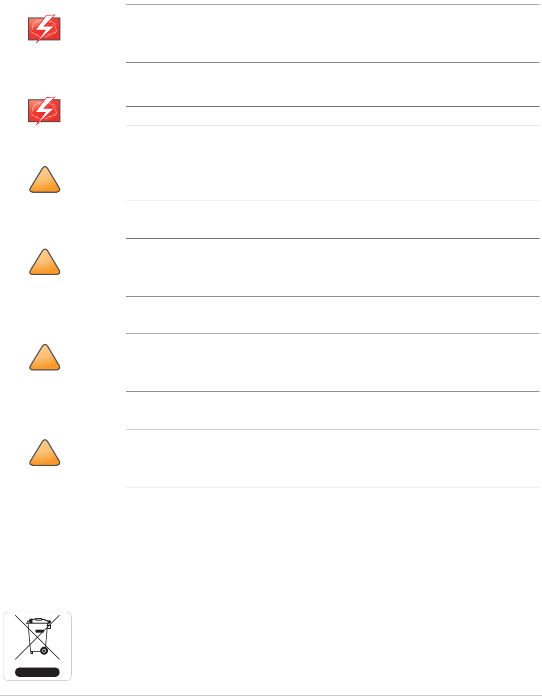
WARNING
Do not open the unit when an explosive atmosphere may be present.
Do not energize or de-energize the unit at the unit’s power connectors when an explosive
atmosphere may be present.
WARNING
Potential Electrostatic Charging Hazard.
!
CAUTION
The antennas installed with the Model AP-85TX should be mounted in a location where they are not
subjected to winds, in order to minimize the build up a charge and potential arcing on the antennas.
!
CAUTION
During all servicing and maintenance activities, the antennas must be handled with extreme caution
to minimize possible electrostatic static discharge (ESD) and arcing events. Any cleaning means, in
particular, should minimize such events on the plastic surfaces of the antennas, which may contain
or produce a charge potential.
!
CAUTION
Only the Model AP-85TX itself is intended to be used in a potentially explosive environment. The
external power adapter, PoE power injector, and power sourcing equipment (PSE, that is,
controllers) are intended to be installed only in a safe environment and are not intended for
installation in a potentially explosive environment.
!
CAUTION
The Model AP-85TX is intended to be powered only by the external power adapter or power injector
provided with the unit, or by power sourcing equipment (PSE) that is compliant with IEEE802.3af.
The product must be powered only by energy-limited circuits, which satisfy the requirements of
EN 60079-15. The explosion group is dependent upon the use of an energy-limited supply circuit.

48 | Product Specifications Aruba AP-85 Outdoor Access Point Series | Installation Guide
European Union RoHS
Aruba products comply with the EU Restriction of Hazardous Substances Directive 2002/95/EC
(RoHS). EU RoHS restricts the use of specific hazardous materials in the manufacture of electrical
and electronic equipment. Specifically, restricted materials under the RoHS Directive are Lead
(including Solder used in printed circuit assemblies), Cadmium, Mercury, Hexavalent Chromium, and Bromine. Some Aruba
products are subject to the exemptions listed in RoHS Directive Annex 7 (Lead in solder used in printed circuit assemblies).
Products and packaging will be marked with the “RoHS” label shown at the left indicating conformance to this Directive.
China RoHS
Aruba products comply with China environmental declaration requirements and are labeled with the “EFUP e”
label shown at the left.

Aruba AP-85 Outdoor Access Point Series | Installation Guide |49
Index
A
AC power................................................................... 12
AC power cable......................................................... 30
access point setup .................................................... 21
accessories ............................................................... 14
antenna...................................................................... 33
beamwidth .......................................................... 34
detachable selection...........................................37
directional ........................................................... 33
gain .....................................................................34
height ..................................................................17
installation........................................................... 31
interfaces ............................................................ 10
omni-directional .................................................. 33
orientation ........................................................... 18
pattern................................................................. 34
pattern plots........................................................ 36
position ............................................................... 18
specifications ...................................................... 36
understanding of................................................. 33
wireless ............................................................... 33
AP-85 Series
about..................................................................... 7
antenna interfaces .............................................. 10
bottom view
AP-85 TX model ........................................... 10
cable connection ................................................ 28
configuration ....................................................... 32
front view .............................................................. 9
installation........................................................... 22
LEDs.................................................................... 13
overview................................................................ 9
package checklist ................................................. 8
power cable connection .....................................30
rear view................................................................ 9
RJ-45 cable connection......................................28
software requirements ..........................................8
specifications ...................................................... 43
top view .............................................................. 10
AP-85FX
100Base-FX ........................................................ 11
console port ........................................................ 11
multi-mode fiber.................................................. 11
AP-85LX
100Base-LX ........................................................ 11
console port ........................................................ 11
single-mode fiber ................................................ 11
AP-85TX
10/100Base-T ports............................................ 10
interfaces ............................................................ 10
LAN..................................................................... 10
PoE ..................................................................... 10
SPoE................................................................... 10
B
beamwidth ................................................................ 34
C
cables........................................................................ 28
cabling........................................................... 19, 28, 30
configuration ............................................................. 32
connecting cables............................................... 28, 30
connectivity ......................................................... 22, 32
console port .............................................................. 11
customer support........................................................ 6
D
DC power ............................................................ 10, 11
DC power cable ........................................................ 30
deployment ............................................................... 15
detachable antennas................................................. 37
directional antenna.................................................... 33
E
environment .............................................................. 19
ethernet cabling ........................................................ 19
F
fiber interface ............................................................ 11
G
gain ........................................................................... 34
grounding .................................................................. 19
grounding point................................................... 11, 12

50 |Aruba AP-85 Outdoor Access Point Series | Installation Guide
I
installation ..................................................... 21, 22, 23
configuration ....................................................... 32
pole mounting (>3.5" Diameter).......................... 26
pole mounting (1.5" to 3.5" Diameter) ................ 24
positioning .......................................................... 27
post-installation connectivity .............................. 32
preparation.......................................................... 23
wall mounting...................................................... 23
L
LC connector............................................................. 11
LEDs ..........................................................................13
lightning arrestor ................................................. 10, 31
line of sight ................................................................ 16
M
mounting ................................................................... 23
multi-mode fiber interface ......................................... 11
N
network setup............................................................21
N-type antenna interfaces......................................... 10
O
omni-directional antenna........................................... 33
operation
modes of ...............................................................7
outdoor conditions .................................................... 19
outdoor deployment.................................................. 15
outdoor planning .......................................................15
overview ...................................................................... 9
P
package checklist........................................................ 8
planning.....................................................................15
PoE ............................................................................ 10
pole mounting (1.5" to 3.5" Diameter)....................... 24
pole moutning (>3.5" Diameter) ................................ 26
positioning.................................................................27
post-installation......................................................... 32
power
AC .......................................................................12
DC .................................................................10, 11
power cables ............................................................. 30
power over ethernet .................................................. 10
pre-installation .......................................................... 23
checklist.............................................................. 21
connectivity ........................................................ 22
network setup..................................................... 21
provisioning ........................................................ 22
provisioning............................................................... 22
R
radio interference ...................................................... 19
radio path planning ................................................... 16
regulatory compliance............................................... 45
RF absorbers............................................................. 15
RF interference sources ............................................ 16
RF reflectors.............................................................. 15
RJ-45 cable............................................................... 28
RSSI LEDs................................................................. 13
RSSI levels ................................................................ 14
S
safety......................................................................... 45
scale requirements.................................................... 15
serial console port..................................................... 11
serial power over ethernet ........................................ 10
single-mode fiber interface ....................................... 11
software requirements ................................................ 8
specifications ............................................................ 43
SPoE ......................................................................... 10
status indicators........................................................ 13
support, customer....................................................... 6
W
wall mounting............................................................ 23
weather ..................................................................... 19
wireless antenna ....................................................... 33