Hewlett Packard Enterprise APEX0100101 Access Point User Manual Professional installation Guide v2
Aruba Networks, Inc. Access Point Professional installation Guide v2
Contents
- 1. Professional installation Guide v2
- 2. Q9DAPEX0100101_User Manual v2
- 3. Installation Guide
Professional installation Guide v2
Professional installation Guide
Product/s covered in this guide:Device: APEX0100 and APEX0101 is part of the
Aruba’s APEX0100 family, implementing dual radio cards each 3x3 MIMO
supporting IEEE 802.11 a/b/g/n/ac operation.
IMPORTANT - Visit Aruba Support web page for the latest information and
documentation related to this product.
IMPORTANT – Please read this document before installing and using your
product. This device must be installed and used in strict accordance with the
manufacturer's instructions. Only approved by the manufacturer power adapters must
be used. For replacement, contact your supplier or distributor.
Installation of this product must comply with local regulations and codes. When this
product is used with external antenna/s, please refer to the installation documentation
provided for the antenna/s. Changes or modifications to the device not approved by the
manufacturer of the product could void the user’s authority to operate the equipment
and will void the warranty of the product. No user serviceable parts; all repairs and
service must be handled by a qualified service center. All products using external
antennas must be professionally installed, and the transmit power of the system must
be adjusted by the professional installer/s to ensure that the system’s EIRP is in
compliance with the limit specified by the regulatory authority of the country of
deployment. During deployment of the system and its initial setup, professional
installer must ensure that the allowed EIRP limit is not exceeded (in the Country of
exploitation of this equipment).
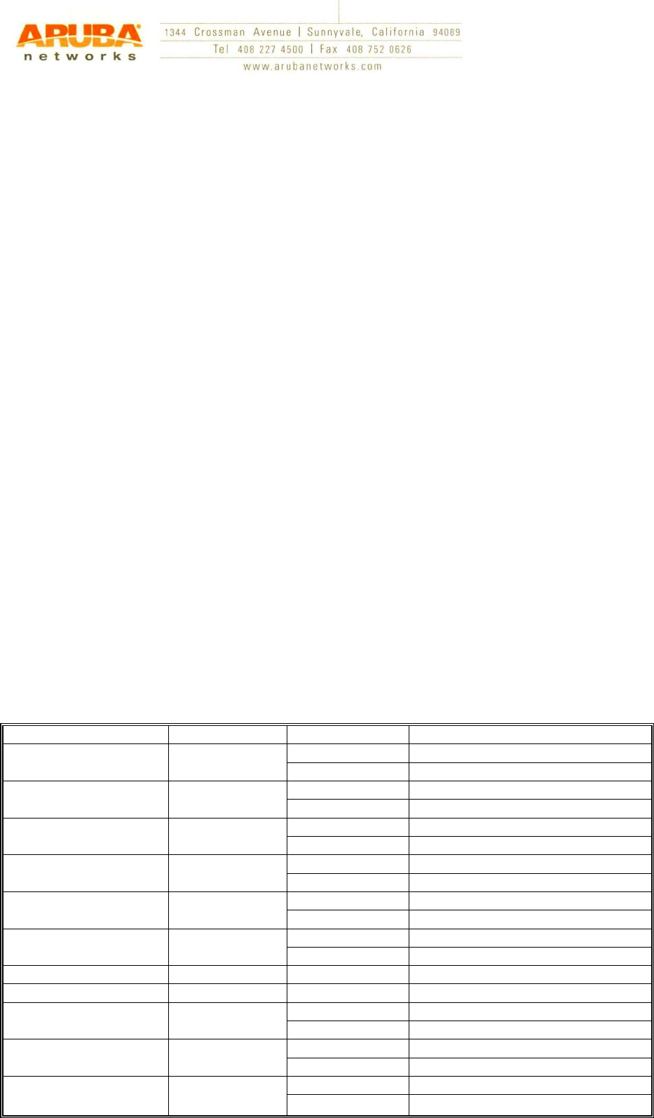
To achieve this professional installer must use approved and recommended by the
Manufacturer antennas,
Model Type Gain ( dBi) Frequency Band ( MHz)
ANT-3X3-2005 Omni 5 2400-2500
NA 4900-5900
ANT-3X3-5005 Omni NA 2400-2500
5 4900-5875
ANT-2X2-D805 Directional 5 2400-2500
5 4900-5875
ANT-3X3-5712 Directional NA 2400-2500
11.5 4900-6000
ANT-2X2-2314 Directional 14 2400-2500
NA 4900-5875
ANT-2X2-5314 Directional NA 2400-2500
14 4900-6000
ANT-2X2-2714 Directional 14 2400-2483
ANT-3X3-5010 Omni 10 4900-5875
ANT-2X2-D607 Directional 7 2400-2500
7 4900-5875
ANT-3X3-D608 Directional 8 2400-2500
8 4900-5900
ANT-3X3-D905 Directional 5 2400-2500
5 4900-5900

and enter Antenna gain in the software using to setup and manage the product. In
additional attenuation between the device and antenna may have to be measured or
calculated. The following formula can be used to calculate from EIRP limit related
RF power based on selected antennas (antenna gain) and feeder (Coaxial Cable loss):
EIRP = Tx RF Power (dBm) +GA (dB) - FL (dB);
EIRP –> limit specific for each Country of deployment
Tx RF Power –> RF power measured at RF connector of the unit
GA –> Antenna gain
FL -> Feeder loss (including the connectors’ loss)
This device has been designed to operate with antennas listed above and having a
maximum gain listed below. Antennas not included in this list or having gain greater
than specified below are strictly prohibited for use with this device. The require
Antenna Impedance is 50 Ohms.
Attention to user and installation person:
According to §2.1091, §2.1093 and §1.1307(b), systems operating under the
provisions of this section shall be operated in a manner that ensures that the public is
not exposed to radio frequency energy level in excess of the Commission’s guidelines.
The power density(S) must less than 1 mW/cm
2
,
S = PG / (4πR
2
)
Where:
S = power density in mW/cm
2
;
P = transmit power in mW;
G = numeric gain of transmit antenna;
R = distance (cm)
(Which according to user manual for a safety use distance,
default 35cm.)
numeric gain=Log
-1
(dB antenna gain/10)
The user and installation person should calculated the Power density(S) before using
and insure that less than 1 mW/cm
2
.
For example:
Where Product transmit power from 2.4GHz band:
Port 0=50mW, port 1=50mW, port 2=50mW,
The total transmit power= port 0+ port 1+ port 2 = 50mW+50mW+50 mW = 150mW;
Where Product transmit power from 5GHz band:
Port 0=50mW, port 1=50mW, port 2=50mW,
The total transmit power= port 0+ port 1+ port 2 = 50mW+50mW+50 mW = 150mW;
If User’s antenna with 14dBi gain max(for 2.4GHz band and 5GHz band),
the numeric gain=Log
-1
(dB antenna gain/10) = Log
-1
(14/10)=25.12dBi;
R=35(cm)(Satety warning in User Manual),
S limit=1mW/cm
2
,
According to the formula:
S = PG / (4πR
2
)
For 2.4GHz band:
S
1
=150*25.12/(4*3.14*35*35)= 0.245<1mW/cm
2
.
For 5GHz band:
S
2
=150*25.12/(4*3.14*35*35)= 0.245<1mW/cm
2
.
S
(Total)
=S
1
+S
2
=0.245+0.245=0.490<1mW/cm
2
.
So,it compliance to FCC rules.
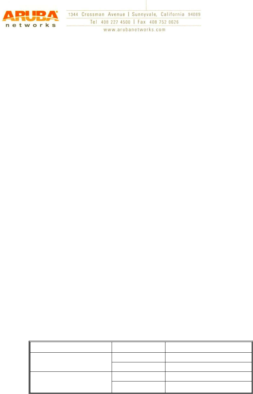
Antenna Types and Maximum Antenna Gains
Frequency Band Type Gain(dBi)
2.4GHz Omni 5
Directional 14
5GHz Omni 10
Directional 14
Note: Antenna information provided above reflect approved antennas for initial
release of the device. For full list of antennas approved/recommended by the
Manufacture please visit the Aruba Networks Inc. web site.