Hewlett Packard Enterprise APEX037457 ACCESS POINT User Manual AP 370 Series IG Rev 01
Hewlett Packard Enterprise Company ACCESS POINT AP 370 Series IG Rev 01
User Manual_20180111_v1 - User Manual r1
Aruba 370 Series Outdoor Access Points
Installation Guide
Rev 02 | January 2018 1
The Aruba 370 Series outdoor wireless access points (AP-374, AP-375 and AP-377) support IEEE 802.11ac Wave 2
standard, delivering high performance with the MU-MIMO (Multi-User Multiple-Input, Multiple-Output)
technology, while also supporting 802.11a/b/g/n wireless services.
The 370 Series outdoor wireless access points provide the following capabilities:
IEEE802.11a/b/g/n/ac operation as a wireless access point
IEEE802.11a/b/g/n/ac operation as a wireless air monitor
IEEE802.11a/b/g/n/ac spectrum monitor
Compatibility with IEEE 802.3at PoE
Guide Overview
“Hardware Overview” on page2 provides a detailed hardware overview of the 370 Series access points.
“Before You Begin” on page6 provides key questions to ask and items to consider when deploying an
outdoor wireless network.
“Installing the Access Point” on page8 describes the multi-step process for a successful installation and
deployment of the 370 Series access points.
“Safety and Regulatory Compliance” on page14 provides an overview of safety and regulatory compliance
information.
Package Contents
370 Series access point
Ethernet cable gland x1
USB console cable x1
Copper lug x1
M4x6 screw x1
Startup guide
Simplified Declaration of Conformity
The weatherproof caps for Ethernet, Console, and power interfaces are connected to the access point, not
loose in the package.
Mounting kits for use with the 370 Series access points are sold separately. Contact your Aruba sales
representative for details.
Inform your supplier if there are any incorrect, missing, or damaged parts. If possible, retain the carton,
including the original packing materials. Use these materials to repack and return the unit to the supplier if
needed.
2Aruba 370 Series Outdoor Access Points | Installation Guide
Hardware Overview
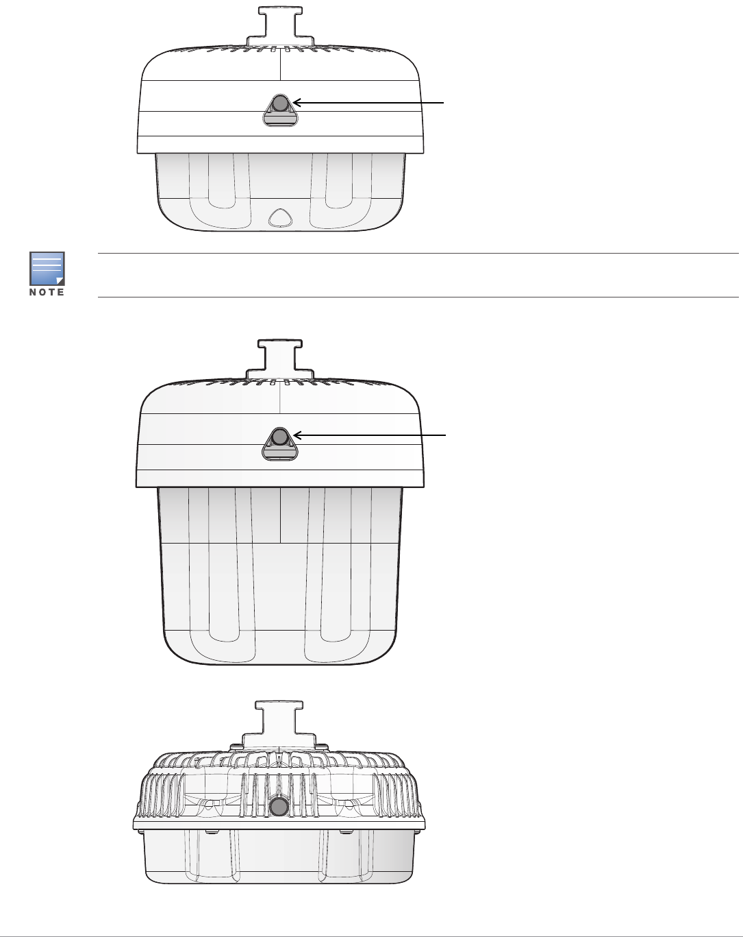
Figure 1 AP-374 Front View (with Aesthetic Cover)
Figure 2 AP-375 Front View
Figure 3 AP-377 Front View
System LED
The antenna connectors of AP-374 are covered by an aesthetic cover. The aesthetic cover can be removed
when necessary.
System LED
Aruba 370 Series Outdoor Access Points | Installation Guide 3
LED
The 370 Series access point is equipped with one LED that indicates the system status of the access point.
Table 1 370 Series LED Meanings during Boot Up
Table 2 370 Series LED Meanings during Operation
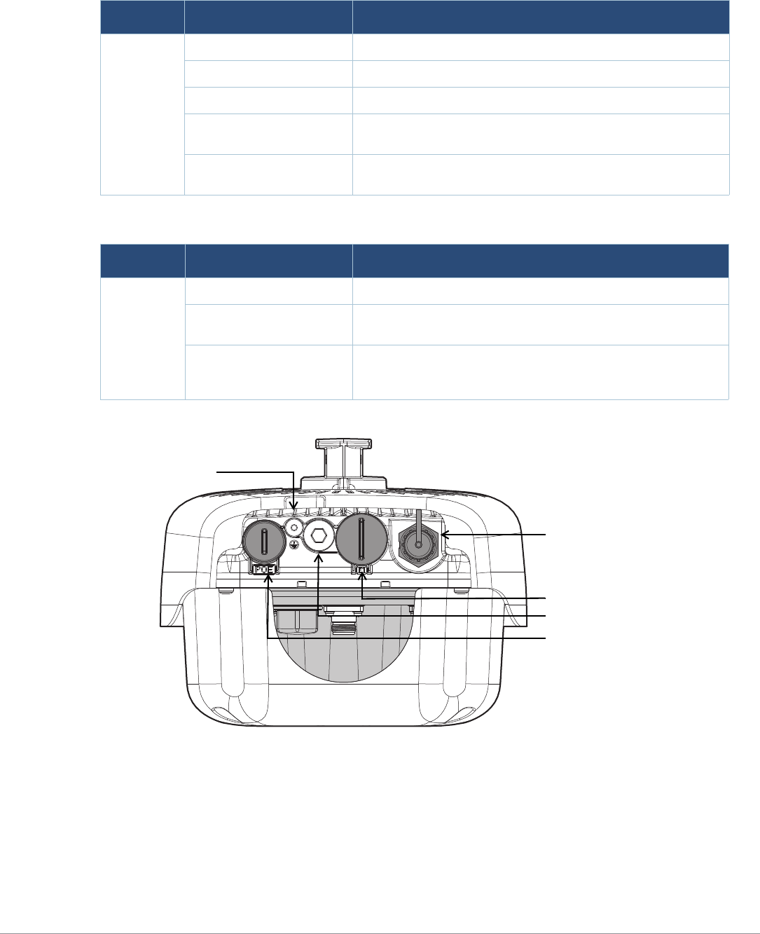
Figure 4 AP-374 Rear View
LED Color/State Meaning
System LED Off No power to AP
Red Initial power-up
Green - Flashing AP booting
Green - Steady AP ready and 1000Mbps Ethernet link established. The LED turns
off after 1200 seconds
Green - Yellow, 6 seconds
period AP ready and 10/100Mbps Ethernet link established. The LED
turns off after 1200 seconds
LED Color/State Meaning
System LED Solid Red General fault
One blink off every 3
seconds Radio 0 fault (5 GHz)
Two quick bl ink off 0.5
seconds apart cycled every
3 seconds
Radio 1 fault (2.4GHz)
AC Power Interface
E1/SFP
E0/POE
Grounding Point
USB Console Port and Reset button
4Aruba 370 Series Outdoor Access Points | Installation Guide
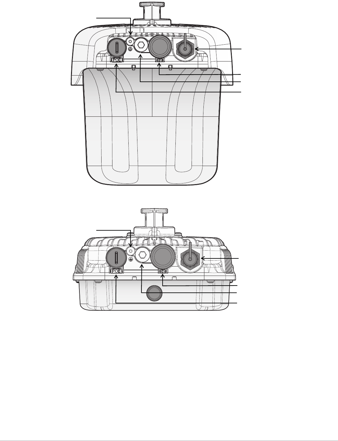
Figure 5 AP-375 Rear View
Figure 6 AP-377 Rear View
E0/POE
The 370 Series access point is equipped with one 10/100/1000 Base-T auto-sensing MDI/MDX Ethernet port. This
port supports wired-network connectivity, in addition to Power over Ethernet (PoE) from IEEE 802.3at compliant
power sources.
This access point accepts 56V DC (802.3at) nominal as a standard powered device (PD) from a Power Sourcing
Equipment (PSE) such as a PoE midspan injector, or network infrastructure that supports PoE.
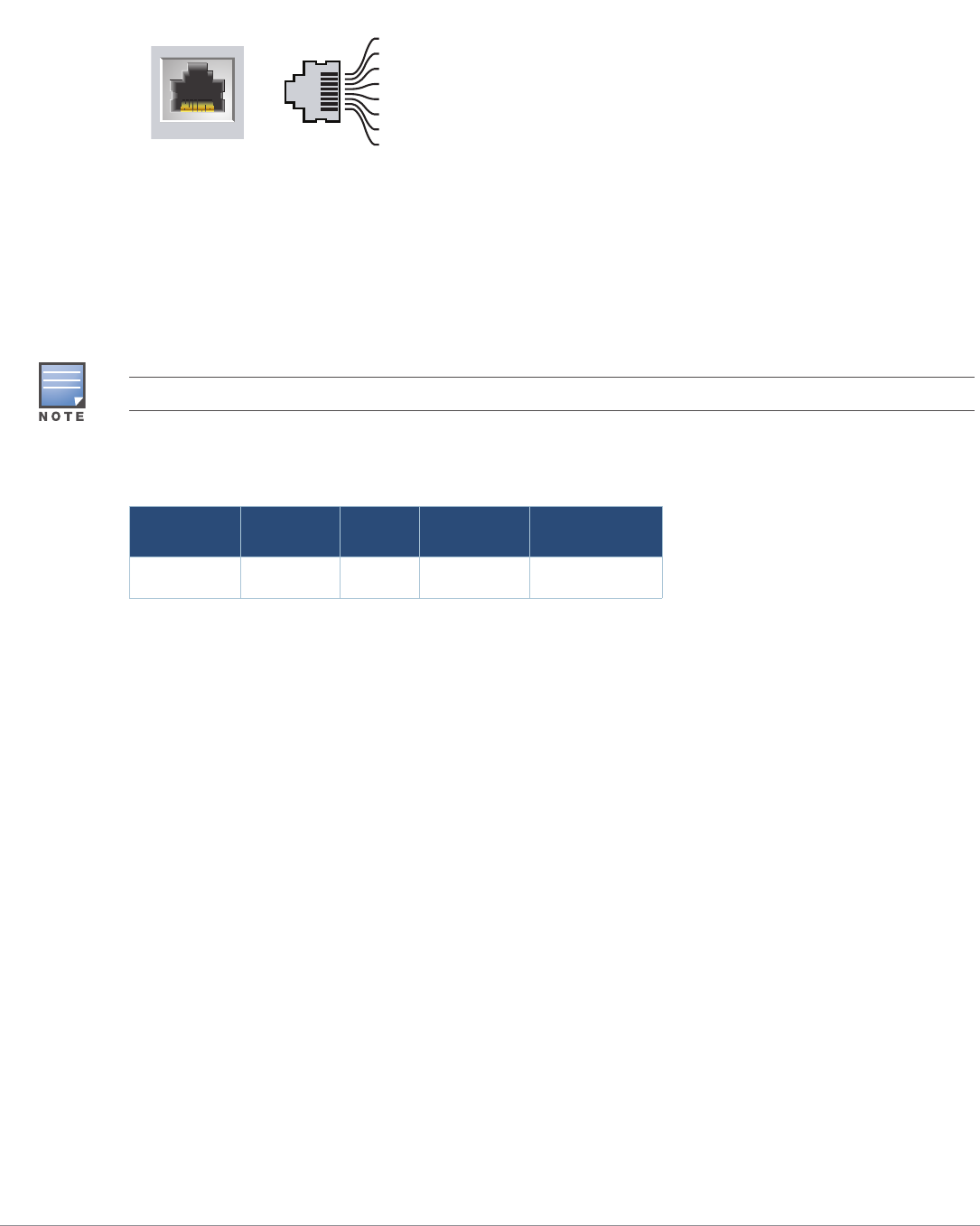
This port has an RJ-45 female connector with the pin-outs shown in Figure 7.
E1/SFP Port
The 370 Series access point is equipped with one 1000 Base-X small form-factor pluggable (SFP) port for fiber-
optic network connections. The applicable SFP modules includes:
Aruba SFP-LX-EXT SFP module (part number: Q8N52A)
Aruba SFP-SX-EXT SFP module (part number Q8N53A)
AC Power Interface
E1/SFP
E0/POE
Grounding Point
USB Console Port and Reset button
AC Power Interface
E1/SFP
E0/POE
Grounding Point
USB Console Port, Reset button & LED
Aruba 370 Series Outdoor Access Points | Installation Guide 5
The applicable SFP cable gland is Aruba CKIT-OD-SFP SFP cable gland (part number: Q8N54A). The SFP module
and cable gland are sold separately. Contact your Aruba sales representative for details.
Figure 7 Gigabit Ethernet Port Pin-Out
Grounding Point
Always remember to protect the access point by installing grounding lines. The ground connection must be
complete before connecting power to the access point enclosure.
USB Console Port
The USB Micro-B console port allows you to connect the access point to a laptop or serial console for direct
management. Use the included USB console cable to connect the access point. You can download the necessary
driver for USB-UART adapter from support.arubanetworks.com under the Tools & Resources tab.
Use the following setting to access the terminal:
Reset Button
The reset button can be used to return the access point to factory default settings. To reset the access point:
1. Power off the AP.
2. Press and hold the reset button using a small, narrow object, such as a paperclip.
3. Power-on the AP without releasing the reset button. The system LED will flash within 5 seconds.
4. Release the reset button.
The system LED will flash again within 15 seconds indicating that the reset is completed. The AP will now
continue to boot with the factory default settings.
AC Power Interface
The 370 Series access point is capable of AC power in the range of 100 - 240 VAC. The power cord or power
connector kit is sold separately.
External Antenna Connectors
The AP-374 access point is equipped with six external antenna connectors. The connectors are labeled 2G0, 2G1,
5G0, 5G1, 5G2, and 5G3.
1000Base-T Gigabit
Ethernet Port
RJ-45 Female
Pin-Out
Signal Name
1
2
3
4
5
6
7
8
BI_DC+
BI_DC-
BI_DD+
BI_DD-
BI_DA+
BI_DA-
BI_DB+
BI_DB-
Function
Bi-directional pair +C, POE Positive
Bi-directional pair -C, POE Positive
Bi-directional pair +D, POE Negative
Bi-directional pair -D, POE Negative
Bi-directional pair +A, POE Negative
Bi-directional pair -A, POE Negative
Bi-directional pair +B, POE Positive
Bi-directional pair -B, POE Positive
You need a proper Allen wrench (8mm) to open the cover of the USB Console port.
Table 3 Console Settings
Baud Rate Data Bits Parity Stop Bits Flow Control
9600 8 None 1 None
6Aruba 370 Series Outdoor Access Points | Installation Guide
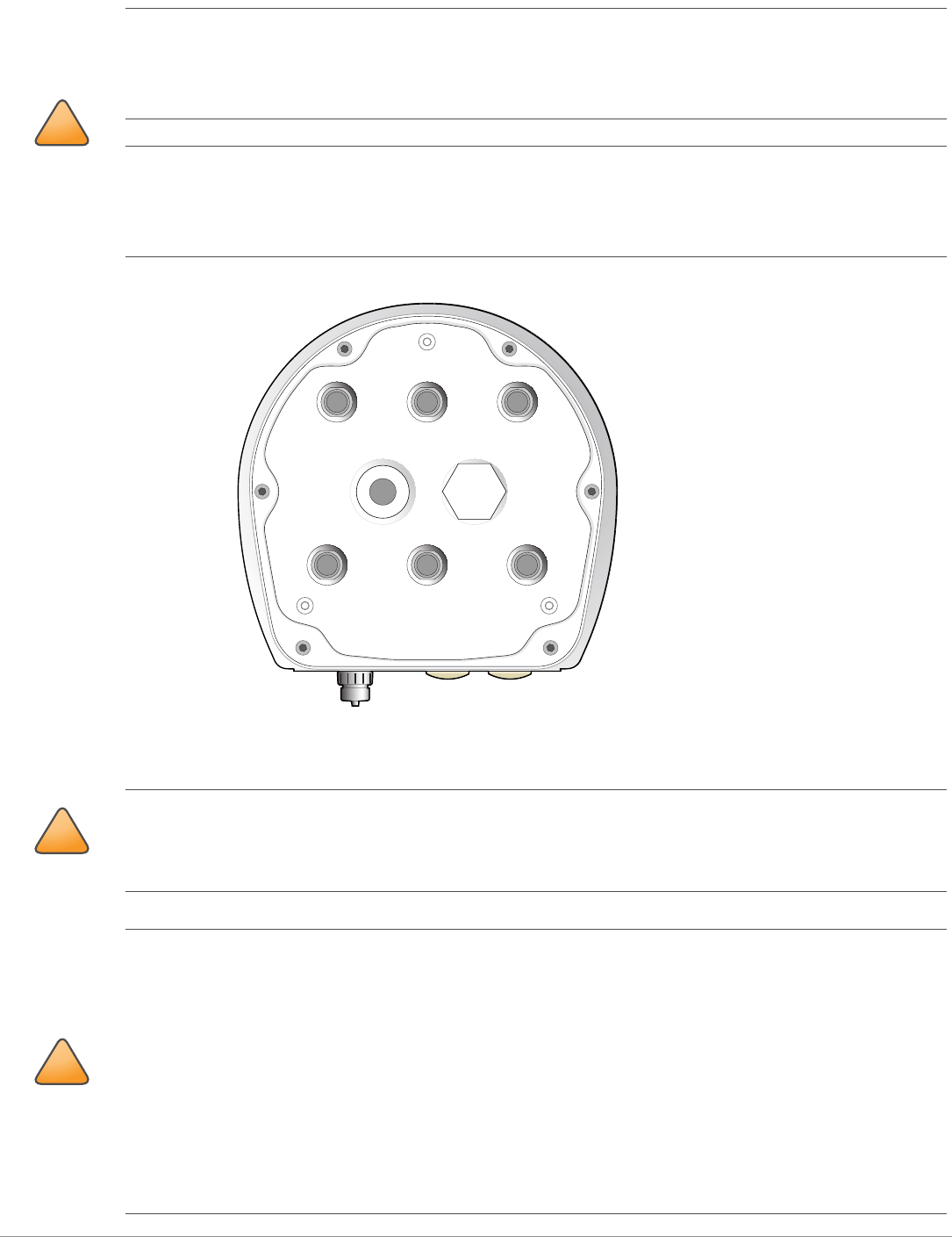
Figure 8 AP-374 Bottom View (without Aesthetic Cover)
Before You Begin
!
CAUTION
External antennas for this device must be installed by an Aruba Certified Mobility Professional (ACMP) or other
Aruba-certified technician, using manufacturer-approved antennas only.
The Equivalent Isotropically Radiated Power (EIRP) levels for all external antenna devices must not exceed the
regulatory limit set by the host country/domain.
Installers are required to record the antenna gain for this device in the system management software.
Les antennes externes pour cet appareil doivent être installées par un professionnel de la mobilité certifié Aruba
(ACMP) ou un autre technicien certifié Aruba, en utilisant uniquement des antennes approuvées par le fabricant.
Les niveaux équivalents de puissance à rayonnement isotrope (EIRP) pour tous les périphériques d'antenne
externe ne doivent pas dépasser la limite réglementaire définie par le pays hôte / domaine.
Les installateurs doivent enregistrer le gain d'antenne pour cet appareil dans le logiciel de gestion du système.
5G1 2G0 5G3
5G2 2G1 5G0
!
CAUTION
FCC Statement: Improper termination of access points installed in the United States configured to non-US
model controllers will be in violation of the FCC grant of equipment authorization. Any such willful or
intentional violation may result in a requirement by the FCC for immediate termination of operation and may
be subject to forfeiture (47 CFR 1.80).
!
CAUTION
EU Statement:
Lower power radio LAN product operating in 2.4 GHz and 5 GHz bands. Please refer to the ArubaOS/Instant
User Guide for details on restrictions.
Produit réseau local radio basse puissance operant dans la bande fréquence 2.4 GHz et 5 GHz. Merci de vous
referrer au ArubaOS/Instant User Guide pour les details des restrictions.
Low Power FunkLAN Produkt, das im 2.4 GHz und im 5 GHz Band arbeitet. Weitere Informationen bezlüglich
Einschränkungen finden Sie im ArubaOS/Instant User Guide.
Apparati Radio LAN a bassa Potenza, operanti a 2.4 GHz e 5 GHz. Fare riferimento alla ArubaOS/Instant User
Guide per avere informazioni detagliate sulle restrizioni.
Aruba 370 Series Outdoor Access Points | Installation Guide 7
Pre-Installation Network Requirements
After WLAN planning is complete and the appropriate products and their placement have been determined, the
Aruba controller(s) must be installed and initial setup performed before the Aruba access points are deployed.
For initial setup of the controller, refer to the ArubaOS Quick Start Guide for the software version installed on your
controller.
Pre-Installation Checklist
Before installing your 370 Series access point, be sure that you have the following:
CAT5E UTP cable or better
IEEE 802.3at compliant PoE source or AC power source
For 370 Series access point running ArubaOS only:
Aruba controller provisioned on the network
Layer 2/3 network connectivity to your access point
One of the following network services:
Aruba Discovery Protocol (ADP)
DNS server with an “A” record
DHCP Server with vendor specific options
Verifying Pre-Installation Connectivity
Before you install access points in a network environment, make sure that the access points will be able to locate
and connect to the controller when they are powered on. Specifically, you must verify the following conditions:
When connected to the network, each access point is assigned a valid IP address.
Access points are able to locate the controller.
Refer to the ArubaOS Quick Start Guide for instructions on locating and connecting to the controller.
Outdoor Planning and Deployment Considerations
Prior to deploying an outdoor wireless network, the environment must be evaluated to plan for a successful
WLAN deployment. Successfully evaluating the environment enables the proper selection of routers and
antennas and assists in the determination of their placement for optimal RF coverage. This process is considered
WLAN or RF planning and Aruba’s system engineers can assist in the outdoor planning process.
The instructions in this section are applicable to the 370 Series access points running ArubaOS only.
Aruba in compliance with governmental requirements, has designed the 370 Series access points so that only
authorized network administrators can change configuration settings. For more information about AP
configuration, refer to the ArubaOS Quick Start Guide and ArubaOS/Instant User Guide.
!
CAUTION
Access points are radio transmission devices and as such are subject to governmental regulation. Network
administrators responsible for the configuration and operation of access points must comply with local
broadcast regulations. Specifically, access points must use channel assignments appropriate to the location in
which the access point will be used.
The instructions in this section are applicable to the 370 Series access points running ArubaOS only.
The rules for the 5600-5650 MHz band vary by region.
8Aruba 370 Series Outdoor Access Points | Installation Guide
Identifying Specific Installation Locations
You can mount the 370 Series access point on a wall or pole. Use the AP placement map generated by Aruba’s RF
Plan software application to determine the proper installation location(s). Each location should be as close as
possible to the center of the intended coverage area and should be free from obstructions or obvious sources of
interference. These RF absorbers/reflectors/interference sources will impact RF propagation and should have
been accounted for during the planning phase and adjusted for in RF plan.
Identifying Known RF Absorbers/Reflectors/Interference Sources
Identifying known RF absorbers, reflectors, and interference sources while in the field during the installation
phase is critical. Make sure that these sources are taken into consideration when you attach an AP to its fixed
location. Examples of sources that degrade RF performance include:
Cement and brick
Objects that contain water
Metal
Microwave ovens
Wireless phones and headsets
Installing the Access Point
Using Mount Kits
The 370 Series access point can be installed on a wall or attached to a pole by using mount kits:
Service to all Aruba products should be performed by trained service personnel only.
Table 4 Applicable Mount Kits for 370 Series Access Point
Part Number Description
JW052A AP-270-MNT-V1 long mount kit for wall and vertical pole mounting, 300 mm from
vertical mounting asset.
JW053A AP-270-MNT-V2 short mount kit for wall and vertical pole mounting, 75 mm from
vertical mounting asset.
JW054A AP-270-MNT-H1 mount kit for hanging from inclined or horizontal structure.
JW055A AP-270-MNT-H2 flush mount kit for wall and ceiling mounting.
The 370 Series access point does not ship with any mount kits. These mount kits are available as accessories
and must be ordered separately.
For installation instructions on AP-270-MNT-V1, AP-270-MNT-V2, AP-270-MNT-H1 and AP-270-MNT-H2 mount
kit, please refer to the AP-270-MNT-V1 Installation Guide, AP-270-MNT-V2 Installation Guide, AP-270-MNT-H1
Installation Guide and AP-270-MNT-H2 Installation Guide respectively.
!
CAUTION
This equipment is intended for installation in a RESTRICTED ACCESS LOCATION attached to a pole or installed
on a wall. Installers should disconnect power before working with or near the AP-377 access point.
Aruba 370 Series Outdoor Access Points | Installation Guide 9
Grounding the Access Point
The grounding must be completed before powering up the access point. The grounding wire should be #8 AWG.
1. Peel the cover of one end of the grounding wire and place the bare grounding wire into the included copper
lug, and press firmly with the crimping pliers.
2. Fasten the copper lug to the grounding hole on the access point with the included M4 x6 screw.
Connecting the Ethernet Cable
To connect the Ethernet cable to the access point, perform the following steps using the Ethernet cable glands
that ships with your access point.
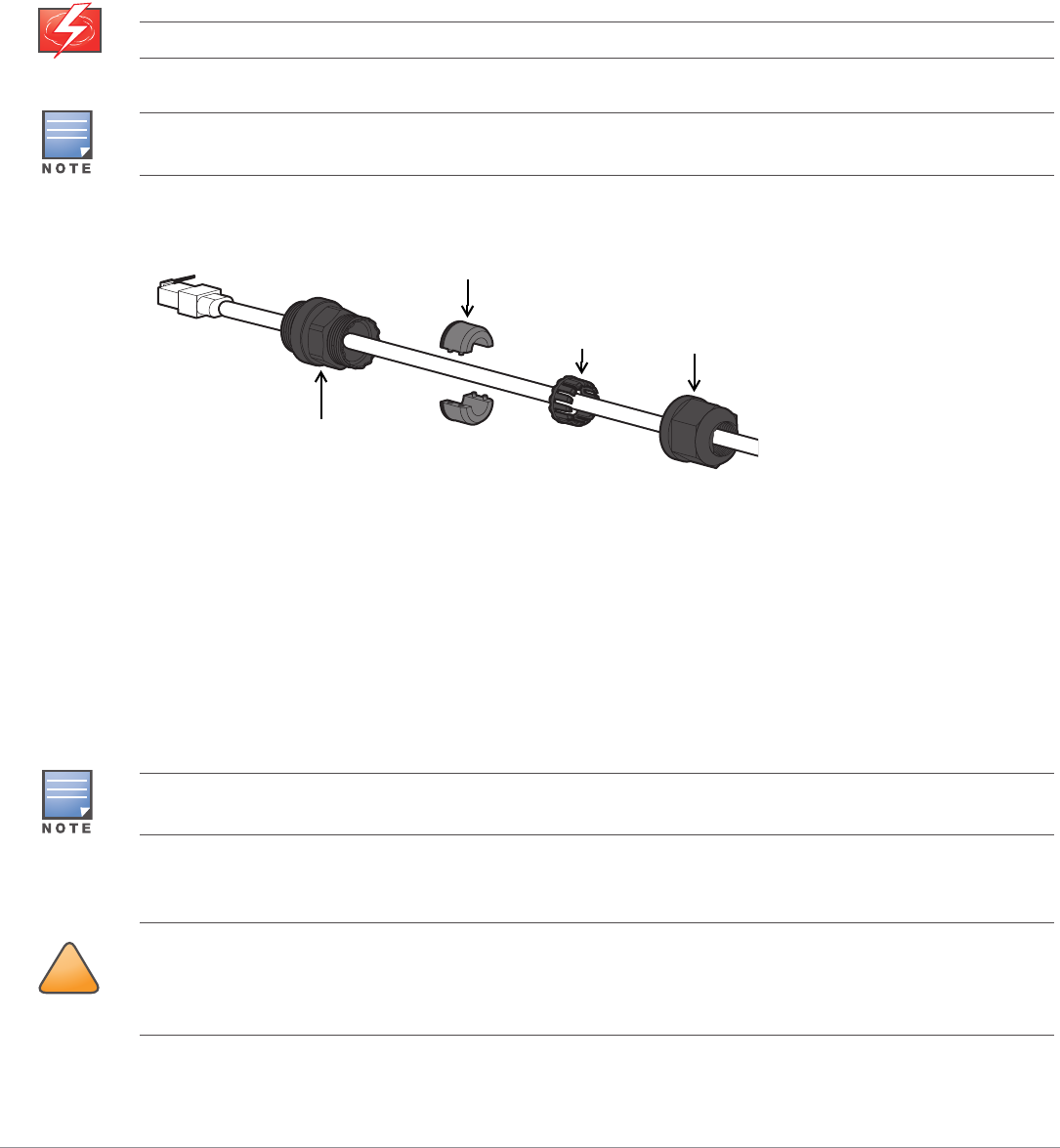
Figure 9 Installing the Ethernet Cable Gland
1. Remove the dust cap from the Ethernet port
2. Slide the sealing nut, clip, split grommet and gland body over the cable.
3. Insert the RJ45 connector to the Ethernet port.
4. Screw the gland body onto the Ethernet port.
5. Combine the two split parts of the grommet over the cable, and move it towards the gland body until it
locates at the recess of the gland body.
6. Move the clip towards the gland body, passing over the grommet, until the wavy end of the clip properly fits
into the wavy end of the gland body.
7. Screw the sealing nut onto the gland body.
Connecting the Power Cable
WARNING
Failure to use the included Ethernet cable glands can lead to connectivity and POE issues.
The cable is not included and must be purchased separately. Purchase a suitable UV-resistant, outdoor rated,
CAT 5E or better RJ45 cable for use with the access point.
Sealing Nut
Clip
Gland Body
Split Grommet
Two grommets are provided in the package for use with the Ethernet cables. One is applicable for cables with
4-6 mm diameter, and another is applicable for cables with 6-10 mm diameter.
!
CAUTION
Installation and service of Aruba products should be performed by Professional Installers in a manner that is
consistent with the electrical code in force in the jurisdiction of deployment. In many countries this will require
a licensed electrician to perform this operation. In Japan, this is a Certified Electrician by Ministry of Economy,
Trade, and Industry.
10 Aruba 370 Series Outdoor Access Points | Installation Guide
The 370 Series product offers two ways to connect the unit to AC power. Two power cord variants are offered
and a connector kit that allows the customer to assemble their own cable if the standard offering does not meet
deployment needs.
The applicable SKUs for these options are:
The difference between the NA and INTL part variants is the color coding of the conductors.
The North American cable uses Black (Hot), White (Neutral), and Green (Ground).
The INTL part follows the international schema of Brown (Hot), Blue (Neutral) and Yellow/Green (Ground)
Best Practice for Outdoor Connection to AC Mains
In all circumstances and with any outdoor infrastructure the recommended practice is to connect to AC mains in
an order grade weather protected junction box. This needs to be implemented by a qualified resource in a
manner that is consistent with the electrical code in force in the jurisdiction of deployment. In many countries
this will require a licensed electrician to perform this operation.
In Japan, this would is a Certified Electrician by Ministry of Economy, Trade and Industry.
The use of plugs with infrastructure equipment is suitable only for temporary installs where nuisance tripping of
GFI plugs is considered tolerable. Should it be desired to attach a plug to the cable assemblies then the installer
is expected to follow all directions provided with the plug end in a fashion consistent with local electrical code.
Use of the CKIT-OD-AC-P
Assembly instructions for this part are shipped with the part. All instructions must be followed to ensure proper
assembly of the connector onto the cable.
The required specifications for third party cable used with the CKIT solution are as follows:
AC power cable specifications (when using AC connector kit and custom cable): minimum voltage/current
rating 250V/1A, diameter 6-12mm, rated for outdoor use and UV exposure
The 370 Series access point does not ship with any power cables. These are available as accessories and should
be ordered separately.
Table 5 SKUs for Powering Options
Part Number Description
JW081A PC-OD-AC-P-NA weatherproof AC power cable(5m), North America version
JW080A PC-OD-AC-P-INT weatherproof AC power cable(5m), International (EU) version
JW079A CKIT-OD-AC-P weatherproof connector kit for AC power interface
!
CAUTION
Please only use included or Aruba specified cables, power cords, AC power supplies and batteries. The power
cord should not be used with other electric equipment than what is specified by Aruba.
Aruba 370 Series Outdoor Access Points | Installation Guide 11
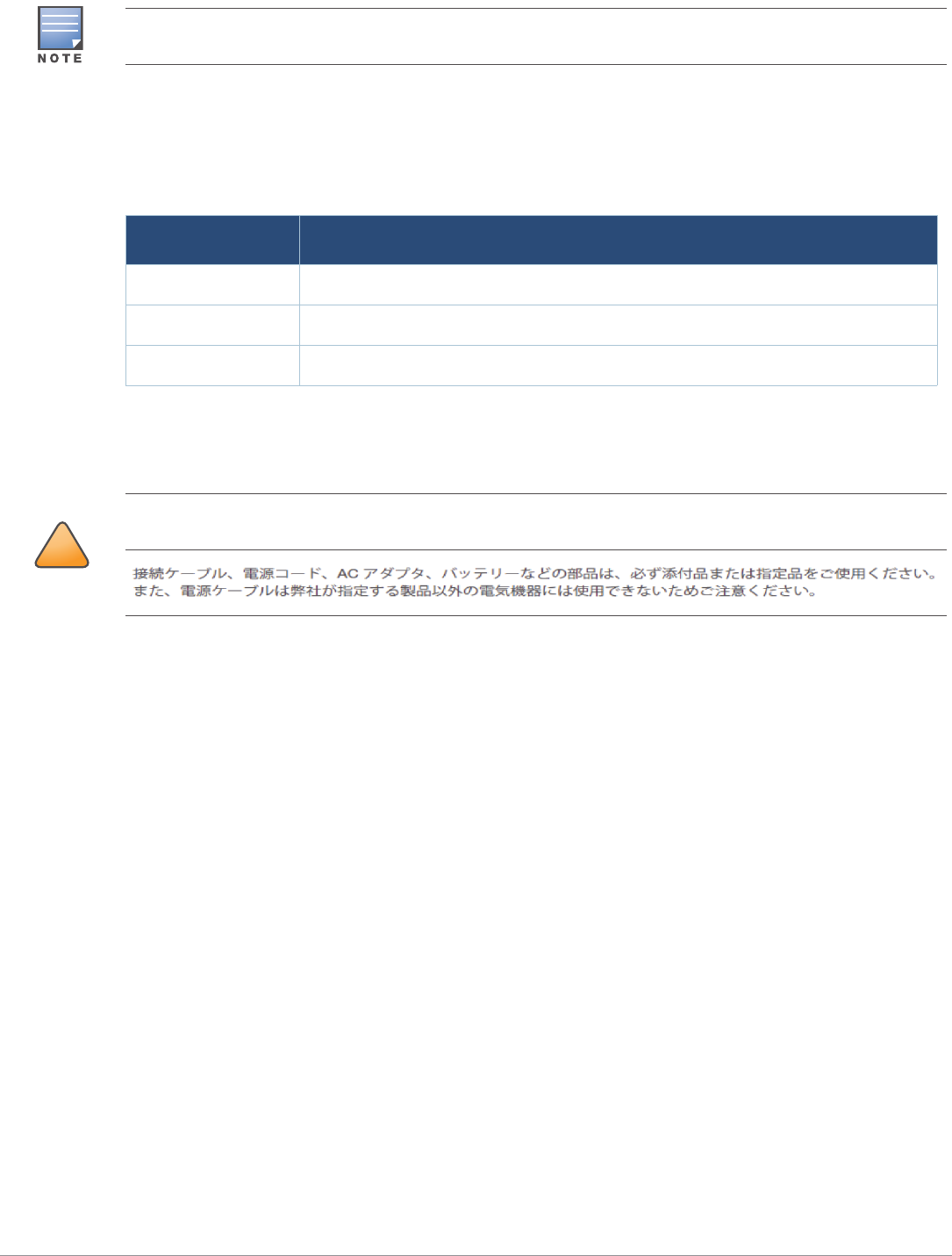
AC Power Cable Connector PIN OUT
Figure 10 AC power cable connector
Connecting the Power Cable
1. Remove the weatherproof cap on the power interface.
2. Insert the power cable connector into the power interface and hand-fasten the locknut.
Connecting the Fiber-optic Cable
To connect the fiber-optic cable to the access point, perform the following steps.
1. Remove the dust cap from the SFP port.
2. Insert the SFP module into the SFP port, and ensure it in place.
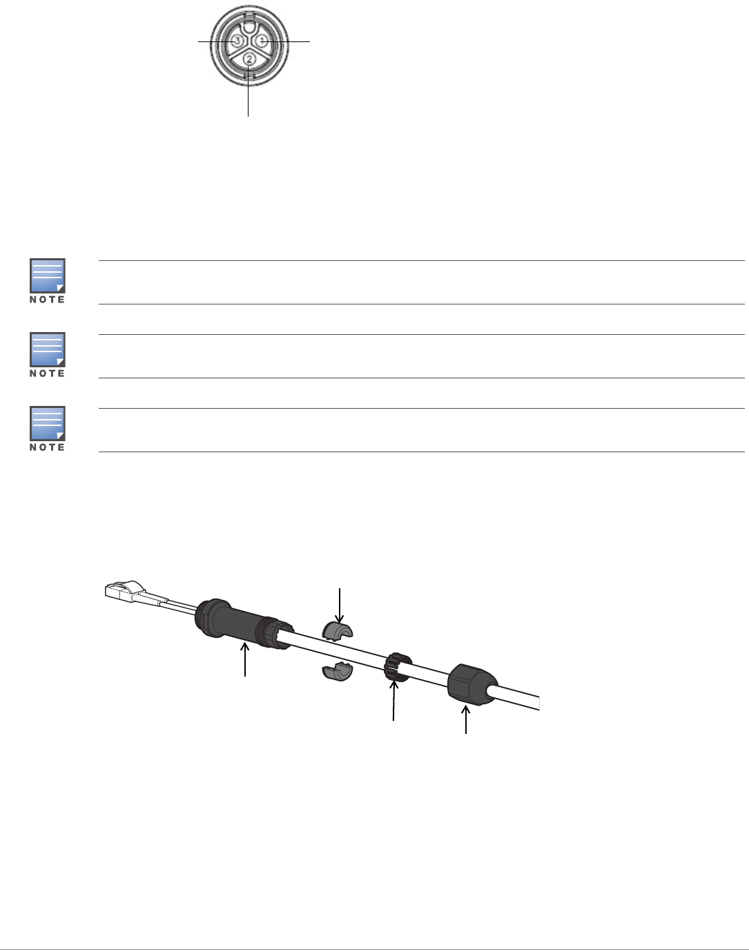
3. Slide the sealing nut, clip, split grommet and gland body over the cable.
Figure 11 Sliding the Fiber-optic Cable Gland Components over the Cable
4. Insert the optic fiber connector of the cable into the SFP module.
5. Screw the gland body onto the SFP port
HotNeutral
Ground
The fiber-optic cable is not included in the package and must be purchased separately. Purchase a suitable
diameter 6-12 mm, UV-resistant, outdoor rated cable for use with the access point.
When the fiber-optic cable (with the cable gland) is connected to the access point, the AP-270-MNT-V2 mount
kit is not applicable for mounting the access point.
When using the AP-270-MNT-H1 mount kit, the access point with the fiber-optic cable (with the cable gland)
connected can only tilt down 30 degree in maximum.
Sealing Nut
Clip
Gland Body
Split Grommet
12 Aruba 370 Series Outdoor Access Points | Installation Guide
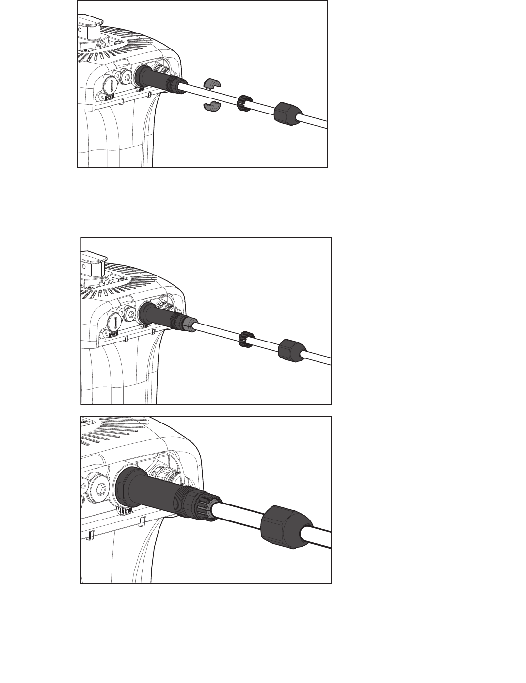
Figure 12 Screwing the Gland Body onto the SFP Port
6. Combine the two split parts of the grommet over the cable, and move it towards the gland body until it
locates at the recess of the gland body.
7. Move the clip towards the gland body, passing over the grommet, until the wavy end of the clip properly fits
into the wavy end of the gland body.
Figure 13 Installing the Fiber-optic Cable Gland
8. Screw the sealing nut onto the gland body.
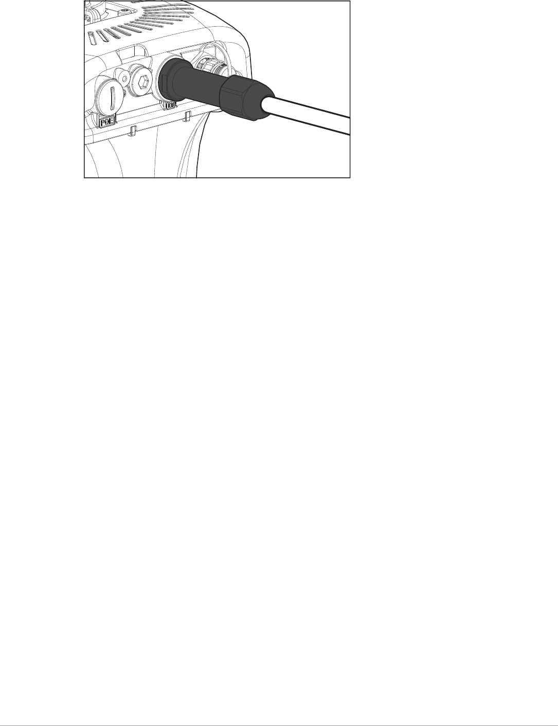
Aruba 370 Series Outdoor Access Points | Installation Guide 13
Figure 14 Completed Installation
Disconnecting the Fiber-optic Cable
To disconnect the fiber-optic cable from the access point, perform the following steps.
1. Turn counterclockwise to loosen the sealing nut.
2. Pull the clip and seal out simultaneously.
3. Unscrew the gland body from the SFP port
4. Depress to release the latch on the cable and simultaneously pull the cable out of the port.
Verifying Post-Installation Connectivity
The integrated LEDs on the access point can be used to verify that the access point is receiving power and
initializing successfully (see Table 1 and Table 2). For instructions on initial setup and software configuration,
refer to the AP Software Quick Start Guide.
Electrical and Environmental Specifications
Electrical
Ethernet
One 10/100/1000Base-T auto-sensing Ethernet RJ-45 Interfaces
Power over Ethernet (IEEE 802.3at compliant)
Power
AC input voltage and current: 100VAC to 240VAC, 0.5A
Connect only to IEC 60950-1 or IEC60601-1 3rd edition products and power sources
Environmental
Operating
Temperature: -40ºC to 65ºC (-40ºF to 149ºF)
Storage
Temperature: -40ºC to 70ºC (-40ºF to 158ºF)
Humidity: 5% to 93% non-condensing
For additional specifications on this product, please refer to the data sheet at www.arubanetworks.com.
Regulatory Model Name
The following regulatory model names apply to the 370 Series:
AP-374: APEX0374
AP-375: APEX0375
14 Aruba 370 Series Outdoor Access Points | Installation Guide
AP-377: APEX0377
Safety and Regulatory Compliance
FCC
To view the FCC ID for controller-managed access points:
1. Log into the controller WebUI
2. Navigate to Maintenance > Controller > About
To view the FCC ID for Instant access points:
1. Log into the virtual controller WebUI
2. Navigate to Maintenance > About
FCC Class B Part 15
This equipment has been tested and found to comply with the limits for a Class B digital device, pursuant to Part
15 of the FCC Rules. These limits are designed to provide reasonable protection against harmful interference in a
residential installation. This equipment generates, uses and can radiate radio frequency energy and, if not
installed and used in accordance with the manufacturer’s instructions, may cause harmful interference to radio
communications.
However, there is no guarantee that interference will not occur in a particular installation. If this equipment does
cause harmful interference to radio or television reception, which can be determined by turning the equipment
off and on, the user is encouraged to try to correct the interference by one or more of the following measures:
Reorient or relocate the receiving antenna.
Increase the separation between the equipment and receiver.
Connect the equipment to an outlet on a circuit different from that to which the receiver is connected.
Consult the dealer or an experienced radio or TV technician for help.
Canada
Under Industry Canada regulations, this radio transmitter may only operate using an antenna of a type and
maximum (or lesser) gain approved for the transmitter by Industry Canada. To reduce potential radio
!
CAUTION
RF Radiation Exposure Statement: This equipment complies with FCC RF radiation exposure limits. This
equipment should be installed and operated with a minimum distance of 13.78 inches (35cm) between the
radiator and your body for 2.4 GHz and 5 GHz operations. This transmitter must not be co-located or operating
in conjunction with any other antenna or transmitter.
!
CAUTION
Déclaration sur les limites d'exposition aux radiofréquences :cet équipement est conforme aux limites
d'exposition aux rayonnements radioélectriques spécifiées par la FCC. Il doit être installé et utilisé à une
distance minimale de 35cm par rapport à votre corps pour les fréquences de 2,4 et 5 GHz. Cet émetteur-
récepteur ne doit pas être utilisé ou situé à proximité d'autres antennes ou émetteurs-récepteurs.
!
CAUTION
The device could automatically discontinue transmission in case of absence of information to transmit, or
operational failure. Note that this is not intended to prohibit transmission of control or signaling information
or the use of repetitive codes where required by the technology.
!
CAUTION
Changes or modifications to this unit not expressly approved by the party responsible for compliance could
void the user’s authority to operate this equipment.
!
CAUTION
Toute modification effectuée sur cet équipement sans l'autorisation expresse de la partie responsable de la
conformité est susceptible d'annuler son droit d'utilisation.
Aruba 370 Series Outdoor Access Points | Installation Guide 15
interference to other users, the antenna type and its gain should be so chosen that the equivalent isotropically
radiated power (e.i.r.p.) is not more than that necessary for successful communication.
This device complies with Industry Canada license-exempt RSS standard(s).
Operation is subject to the following two conditions: (1) this device may not cause interference, and (2) this
device must accept any interference, including interference that may cause undesired operation of the device.
Déclaration d’Industrie Canada
Le présent appareil est conforme aux CNR d'Industrie Canada applicables aux appareils radio exempts de
licence. L'exploitation est autorisée aux deux conditions suivantes : (1) l'appareil ne doit pas produire de
brouillage, et (2) l'utilisateur de l'appareil doit accepter tout brouillage radioélectrique subi, même si le brouillage
est susceptible d'en compromettre le fonctionnement.
Canadian Caution
This radio transmitter (identify the device by certification number, or model number ifCategory II) has been
approved by Industry Canada to operate with the antenna typeslisted below with the maximum permissible
gain and required antenna impedance foreach antenna type indicated. Antenna types not included in this list,
having a gaingreater than the maximum gain indicated for that type, are strictly prohibited for usewith this
device.
Le présent émetteur radio (identifier le dispositif par son numéro de certification ouson numéro de modèle s'il
fait partie du matériel de catégorie I) a été approuvé parIndustrie Canada pour fonctionner avec les types
d'antenne énumérés ci-dessous etayant un gain admissible maximal et l'impédance requise pour chaque type
d'antenne.Les types d'antenne non inclus dans cette liste, ou dont le gain est supérieur au gain
maximal indiqué, sont strictement interdits pour l'exploitation de l'émetteur.
EU Regulatory Conformance
Aruba hereby declares that the 370 Series wireless access points are in compliance with
directives listed below:
EMC Directive 2014
Low Voltage Directive 2014
RED Directive 2014
REACH Regulation (EC) No.: 1907/2006
RoHS Directive 2011
WEEE Directive 2012
A Declaration of Conformity for these directives is available for viewing at www.arubanetworks.com.
Medical
1. Equipment not suitable for use in the presence of flammable mixtures.
No. P/N Gain
1ANT-4x4-531414dBi@5.8GHz
2 ANT-2x2-2005 5dBi@2.4GHz
3ANT-2x2-5005 5dBi@5GHz
4ANT-3x3-D6087.5dBi min @2.4GHz;
7.5dBi min @5.8GHz
5 ANT-3x3-D100 5dBi@2.4GHz;
5dBi@5.8GHz
6ANT-3x3-571211.5dBi@5.8GHz
7ANT-2x2-231414dBi@2.4GHz
8MT-484052/NVH16dBi@5.8GHz
16 Aruba 370 Series Outdoor Access Points | Installation Guide
2. Connect to only IEC 60950-1 or IEC 60601-1 certified products and power sources. The end user is
responsible for the resulting medical system complies with the requirements of IEC 60601-1.
3. Wipe with a dry cloth, no additional maintenance required.
4. No serviceable parts, the unit must be sent back to the manufacturer for repair.
5. No modifications are allowed without Aruba approval.
This device intended to be installed outdoors.
This device has no IEC/EN60601-1-2 essential performance.
!
CAUTION
Use of this equipment adjacent to or stacked with other equipment should be avoided because it could result
in improper operation. If such use is necessary, this equipment and the other equipment should be observed
to verify that they are operating normally.
Compliance is based on the use of Aruba approved accessories. Refer to the ordering guide for this access
point at www.arubanetworks.com.
!
CAUTION
Use of accessories, transducers and cables other than those specified or provided by the manufacturer of this
equipment could result in increased electromagnetic emissions or decreased electromagnetic immunity of this
equipment and result in improper operation.
!
CAUTION
Portable RF communications equipment (including peripherals such as antenna cables and external antennas)
should be used no closer than 30 cm (12 inches) to any part of the access point. Otherwise, degradation of the
performance of this equipment could result.
The emissions characteristics of this equipment make it suitable for use in industrial areas and hospitals (CISPR
11 class A). If it is used in a residential environment (for which CISPR 11 class B is normally required) this
equipment might not offer adequate protection to radio-frequency communication services. The user might
need to take mitigation measures, such as relocating or re-orienting the equipment.
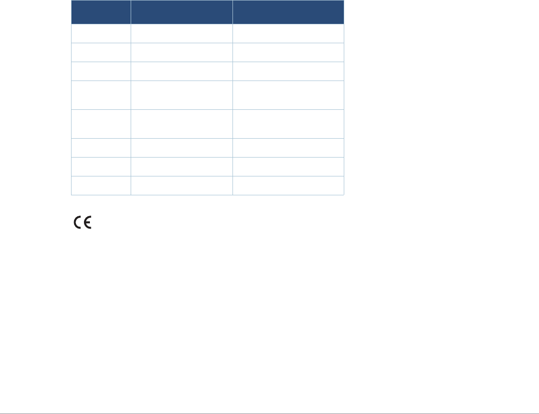
Radio Type Frequency Range Power (EIRP) Modulation
BLE 2400-2483.5MHz <10dBm GFSK
802.11 2400-2483.5MHz 20dBm CCK, OFDM
802.11 5150-5250MHz 23dBm OFDM
802.11 5250-5350MHz 23dBm OFDM
802.11 5500-5700MHz 30dBm OFDM
802.11 5725-5850MHz 36dBm OFDM
Actual output power values will depend on national restrictions and the antennas used.

Aruba 370 Series Outdoor Access Points | Installation Guide 17
Taiwan
第十二條
經型式認證合格之低功率射頻電機,非經許可,公司、商號或使用者均不得擅自變更頻率、加大功率或變更原設計之特性及功
能。
第十四條
低功率射頻電機之使用不得影響飛航安全及干擾合法通信;經發現有干擾現象時,應立即停用,並改善至無干擾時方得繼續使
用。
前項合法通信,指依電信法規定作業之無線電通信。
低功率射頻電機須忍受合法通信或工業、科學及醫療用電波輻射性電 機設備之干擾。
Brazil
Este equipamento não tem direito à proteção contra interferência prejudicial e não pode causar interferência
em sistemas devidamente autorizados.
México
La operación de este equipo está sujeta a las siguientes dos condiciones: (1) es posible que este equipo o
dispositivo no cause interferencia perjudicial y (2) este equipo o dispositivo debeaceptar cualquier interferencia,
incluyendo la que pueda causar su operación no deseada.
Proper Disposal of Aruba Equipment
For the most current information about Global Environmental Compliance and Aruba products, see our website
at www.arubanetworks.com.
Waste of Electrical and Electronic Equipment
Aruba products at end of life are subject to separate collection and treatment in the EU
Member States, Norway, and Switzerland and therefore are marked with the symbol shown
at the left (crossed-out wheelie bin). The treatment applied at end of life of these products in
these countries shall comply with the applicable national laws of countries implementing
Directive 2002/96EC on Waste of Electrical and Electronic Equipment (WEEE).
Complies with: Emissions - CISPR11/EN55011, Group 1,
Class B
Immunity:
Electrostatic discharge: +/-8kV contact/ +/-15kV air
Radiated RF EM fields: 80MHz - 2.7GHz, 3V/m
Proximity fields from RF wireless communication
equipment: per Table 9 of the IEC/EN 606010-1-2
RATED power frequency magnetic fields: 30A/m
Electrical Fast Transients: +/-2kV
Surges (line-to-line): +/- 0.5, 1.0
Surges (line-to-ground): +/- 0.5, 1.0, 2kV
Conducted disturbances induced by RF fields: 0.15MHz-80MHz, 3Vrms
Voltage Dips: 0%, 0.5 cycles, 0%, 1 cycle, 70% 25/30
cycles
Voltage Interruptions: 0% 250/300 cycles
18 Aruba 370 Series Outdoor Access Points | Installation Guide
European Union RoHS
Aruba products also comply with the EU Restriction of Hazardous Substances Directive
2011/65/EC (RoHS). EU RoHS restricts the use of specific hazardous materials in the
manufacture of electrical and electronic equipment. Specifically, restricted materials
under the RoHS Directive are Lead (including Solder used in printed circuit assemblies),
Cadmium, Mercury, Hexavalent Chromium, and Bromine. Some Aruba products are subject to the exemptions
listed in RoHS Directive Annex 7 (Lead in solder used in printed circuit assemblies). Products and packaging will
be marked with the “RoHS” label shown at the left indicating conformance to this Directive.
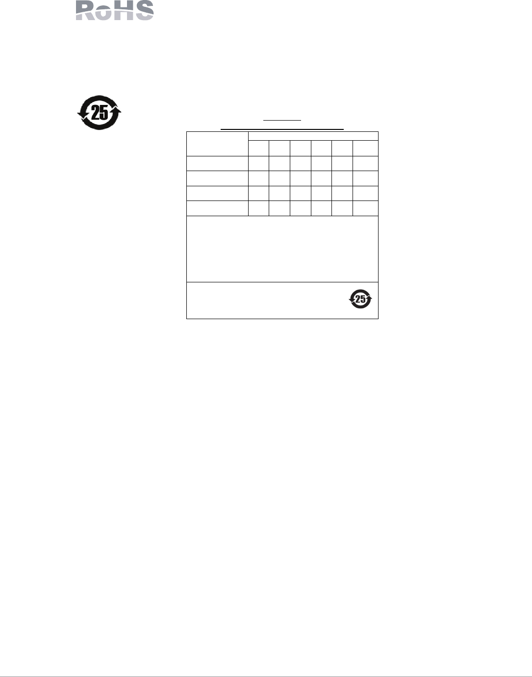
China RoHS
Aruba products also comply with China environmental declaration requirements and are labeled
with the “EFUP 25” label shown at the left.
ᴹᴹ∂ᴹᇣ⢙䍘༠᰾
Hazardous Materials Declaration
䜘Ԧ〠
(Parts)
ᴹ∂ᴹᇣ⢙䍘ᡆݳ㍐˄Hazardous Substance˅
䫵
˄Pb˅
⊎
˄Hg˅
䭹
˄Cd˅
ޝԧ䬜
˄Cr6+˅
ཊⓤ㚄㤟
˄PBB˅
ཊⓤҼ㤟䟊
˄PBDE˅
⭥䐟⁑ඇ
(circuit modules) XOOOO O
⭥㔶৺⭥㔶㓴Ԧ
(Cables & Cable A
ssemblies)
OOOOO O
䠁䜘Ԧ
(Metal Parts) OOOOO O
ກᯉ઼㚊ਸ⢙䜘Ԧ
(
Plastic and Polymeric Parts)
OOOOO O
O: 㺘⽪䈕ᴹ∂ᴹᇣ⢙䍘൘䈕䜘Ԧᡰᴹ൷䍘ᶀᯉѝⲴਜ਼䟿൷൘ SJ/T11363-2006 ḷ߶㿴ᇊⲴ䲀䟿㾱≲
ԕлDŽ
Indicates that the concentration of the hazardous substance in all homogeneous materials in the parts
is below the relevant threshold of the SJ/T11363-2006 standard.
X: 㺘⽪䈕ᴹ∂ᴹᇣ⢙䍘㠣ቁ൘䈕䜘ԦⲴḀа൷䍘ᶀᯉѝⲴਜ਼䟿䎵ࠪ SJ/T11363-2006 ḷ߶㿴ᇊⲴ䲀
䟿㾱≲DŽIndicates that the concentration of the hazardous substance of at least one of all homogeneous
materials in the parts is above the relevant threshold of the SJ/T11363-2006 standard.
ሩ䬰ѻᰕⲴᡰӗ૱ˈᵜ㺘ᱮ⽪ᓄ䬮Ⲵ⭥ᆀؑӗ૱ਟ㜭वਜ਼䘉Ӌ⢙䍘DŽ
This table shows where these substances may be found in the supply chain of
electronic information
products, as
of the date of sal
e of the enclosed product.
↔ḷᘇѪ䪸ሩᡰ⎹৺ӗ૱Ⲵ⧟؍֯⭘ᵏḷᘇ.ḀӋ䴦䜘ԦՊᴹањн਼Ⲵ⧟؍֯⭘ᵏ
(
ֻྲ,⭥⊐অݳ⁑ඇ)䍤൘ަӗ૱к.
↔⧟؍֯⭘ᵏ䲀ਚ䘲⭘Ҿӗ૱ᱟ൘ӗ૱ѝᡰ㿴ᇊⲴᶑԦлᐕ.
The Environment
-
Friendly Use Period (EFUP) for all enclosed products and their parts are
per the symbol shown here. The Environment
-
Friendly Use Period is valid only when the
product is operated under the conditions defined in the product manual.
www.arubanetworks.com
3333 Scott Boulevard
Santa Clara, California 95054
USA
Aruba 370 Series Outdoor Access Points | Installation Guide 19
Contacting Support
Copyright
© Copyright 2017 Hewlett Packard Enterprise Development LP
Open Source Code
This product includes code licensed under the GNU General Public License, the GNU Lesser General Public
License, and/or certain other open source licenses. A complete machine-readable copy of the source code
corresponding to such code is available upon request. This offer is valid to anyone in receipt of this information
and shall expire three years following the date of the final distribution of this product version by Hewlett Packard
Enterprise Company. To obtain such source code, send a check or money order in the amount of US $10.00 to:
Hewlett Packard Enterprise Company
Attn: General Counsel
3000 Hanover Street
Palo Alto, CA 94304
USA
Warranty
This hardware product is protected by an Aruba warranty. For details, see Aruba Networks standard warranty
terms and conditions.
Main Site arubanetworks.com
Support Site support.arubanetworks.com
Airheads Social Forums and Knowledge
Base
community.arubanetworks.com
North American Telephone 1-800-943-4526 (Toll Free)
1-408-754-1200
International Telephones arubanetworks.com/support-services/contact-support/
Software Licensing Site hpe.com/networking/support
End-of-life Information arubanetworks.com/support-services/end-of-life
Security Incident
Response Team (SIRT)
Site: arubanetworks.com/support-service/security-bulletins/
Email: sirt@arubanetworks.com