Hewlett Packard Enterprise APIN0224225 Wireless Access Point User Manual AP 22X Installation Guide Rev 01
Aruba Networks, Inc. Wireless Access Point AP 22X Installation Guide Rev 01
Contents
- 1. Installation Guide
- 2. Manual
- 3. Instal Guide
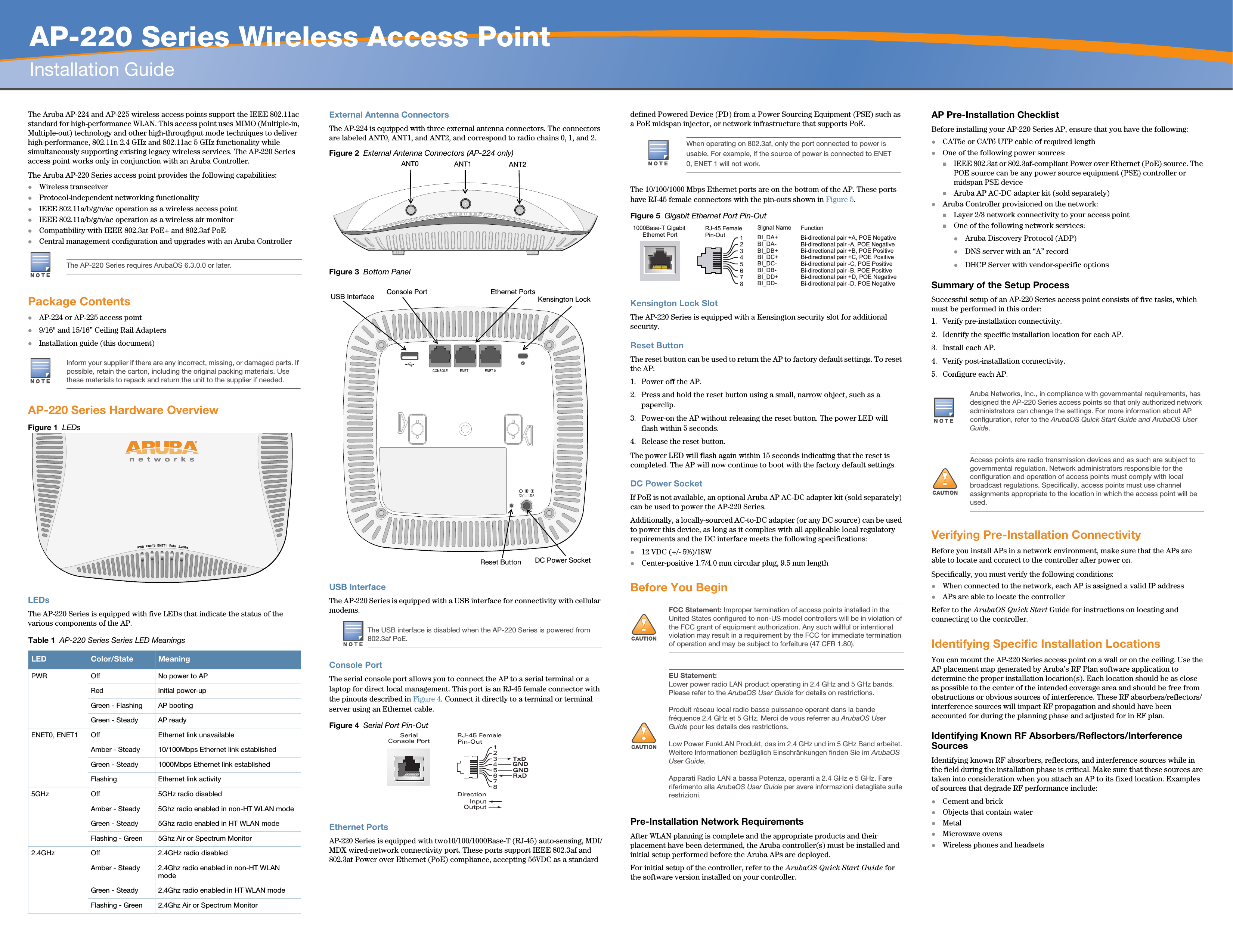
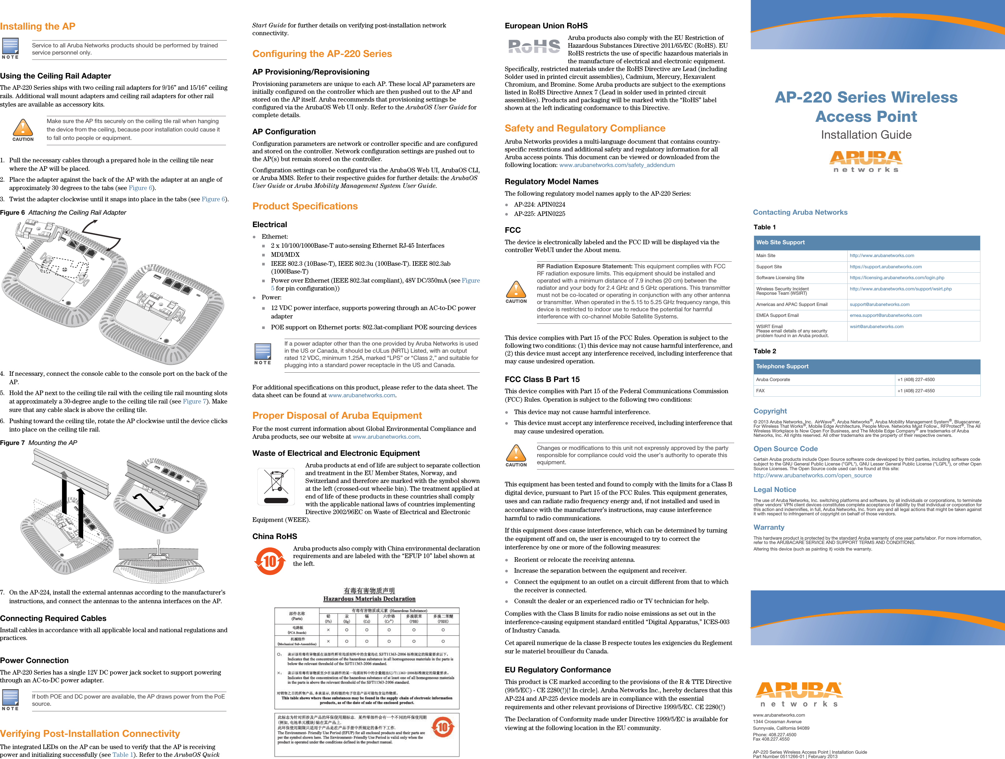
Installation Guide