Hewlett Packard Enterprise APIN0324325 Wireless Access Point User Manual 0511816 03 xAP 32x IG
Aruba Networks, Inc. Wireless Access Point 0511816 03 xAP 32x IG
Contents
- 1. User manual
- 2. Regulatory and safety Manual
- 3. User Manual
- 4. Manual
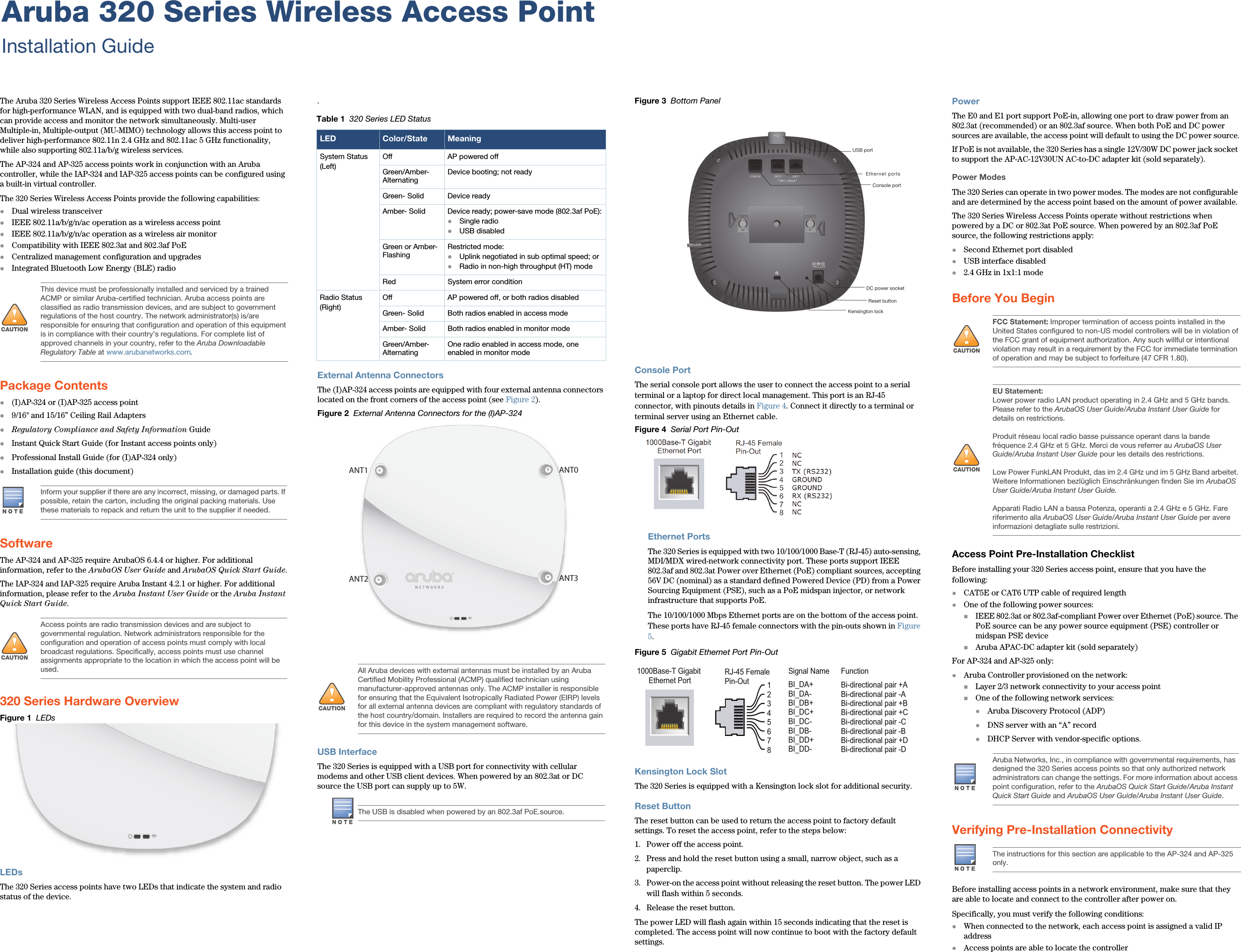
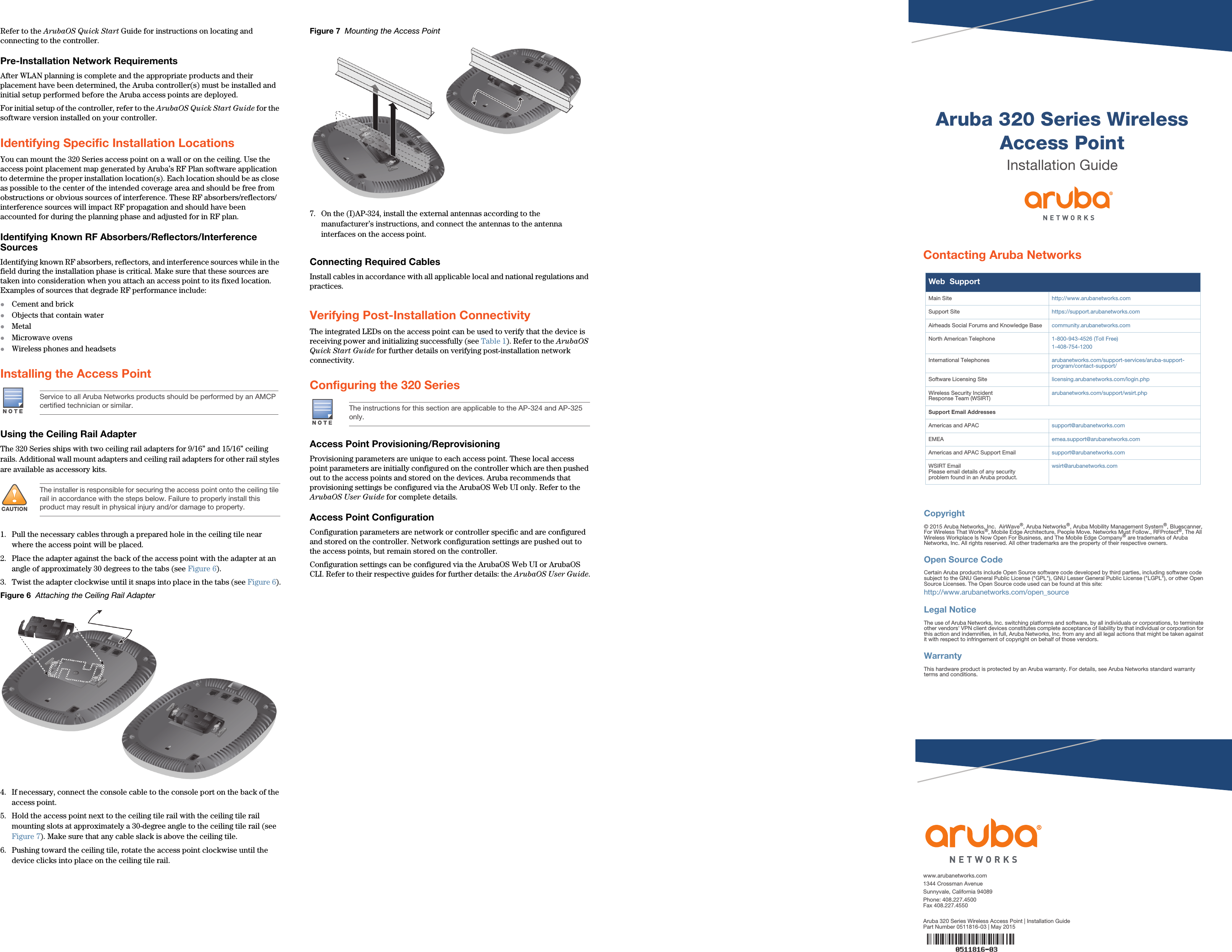
User manual