Hewlett Packard Enterprise APINH205 Hospitality Dual Band AP User Manual AP 205H IG Rev 01 4
Aruba Networks, Inc. Hospitality Dual Band AP AP 205H IG Rev 01 4
Contents
- 1. User Manual
- 2. USer Manual
User Manual
Aruba AP-205H Wireless Access Point
Installation Guide
The Aruba AP-205H access point is a high-performance dual radio wireless and wired
access point for hospitality and branch deployments.
This device combines high-performance wireless mobility with Gigabit wired local access
to deliver secure network access to dormitories, hotel rooms, classrooms, medical clinics,
and multi-tenant environments. MIMO (Multiple-Input, Multiple-Output) technology
enables the AP-205H to provide wireless 2.4 GHz 802.11n and 5 GHz 802.11n/ac
functionality, while simultaneously supporting existing 802.11a/b/g wireless services.
The AP-205H can be easily converted into a desk-mounted remote AP for branch office
deployments with the AP-205H-MNTR mounting kit (sold separately), or attached to a
wall box using the bracket included using the existing structured cable system.
The AP-205H access point works in conjunction with an Aruba controller, while the IAP-
205H variant uses a built-in virtual controller.
The Aruba AP-205H access point provides the following capabilities:
Dual wireless transceivers
Protocol-independent networking functionality (no idea what this means)
IEEE 802.11a/b/g/n/ac operation as a wireless access point
IEEE 802.11a/b/g/n/ac operation as a wireless air monitor, spectrum analyzer
Compatibility with IEEE 802.3af/at PoE
Central management configuration and upgrades through an Aruba Controller or
Aruba Instant virtual controller
POE power sourcing to an attached POE network device
Support for selected USB peripherals
Package Contents
AP-205H Access Point
Single Gang Wall-box Mounting bracket
2x #6-32 Machine Screw
Torx Security Screw
Installation Guide (this document)
Hardware Overview
Figure 1 Front
LED
The AP-205H is equipped with two LEDs indicating System Status and PSE.
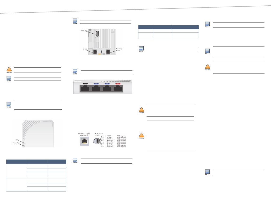
Figure 2 Rear
Console Port
The serial console port allows you to connect the AP to a serial terminal or a laptop for
direct local management. This port located at the rear of the AP-205H, is a 4-pin connector
with removable dust cover. An optional serial adapter cable (AP-CBL-SER) compatible
with the AP-205H, is sold separately.
Figure 3 Bottom
Ethernet Ports
AP-205H is equipped with a total of four active Ethernet ports (E0-E3). E0 is 10/100/1000
Base-T (RJ-45) auto-sensing, MDI/MDX wired-network uplink connectivity port that is
primarily used as a passthrough port, but can alternatively serve as E0 if the E0 and PT
ports are physically bridged by a jumper cable (sold separately with the AP-205H-MNTR
RAP Conversion Kit). This port supports IEEE 802.3af Power over Ethernet (PoE),
accepting 48VDC as a standard defined Powered Device (PD) from a Power Sourcing
Equipment (PSE) such as a PoE midspan injector or network infrastructure that supports
PoE.
Ports E1-E3 are 10/100/1000 Base-T (RJ-45) auto-sensing, MDI/MDX wired-network
downlink connectivity ports, used to provide secure network connectivity to wired
devices. E0 is located on the rear of the AP, while the E1-E3 are located on the bottom
(Figure 3).
Additionally, AP-205H supports a passive pass-through RJ-45 interface to extend a
physical connection (typically another Ethernet connection) from the back of the device
to a connector on the bottom.
Figure 4 Gigabit Ethernet Port Pin-Out
USB Interface
The AP-205H Series is equipped with a USB interface that is compatible with cellular
modems and BLE dongles. When active, this USB port can supply up to 5W (1A).
Power Supply
The AP-205H has a single 48V DC power connector to support powering through an AC-to-
DC power adapter. AP-AC-48V36 sold separately.
When the AP-205H is powered by high-power, POE and POE-PSE on E3 is enabled and
power to the powered device will be limited to 10W. When attempting to draw additional
power, the AP will disable power on port E3. This port will automatically reactivate over
time.
Push Button
The push button located on the right side of the AP can be used to reset the AP to factory
default settings or turn off/on the LED display.
To reset the AP to factory default settings:
1. Power off the AP.
2. Press and hold the push button using a small, narrow object, such as a paperclip.
3. Power-on the AP without releasing the push button. The system status LED will
flash within 5 seconds.
4. Release the push button.
The system status LED will flash again within 15 seconds indicating that the reset is
completed. The AP will now continue to boot with the factory default settings.
To turn off/on the system status LED:
During the normal operation of the AP, press the push button using a small, narrow
object, such as a paperclip. The system status LED will be turned off/on immediately.
Before You Begin
Pre-Installation Network Requirements
After WLAN planning is complete and the appropriate products and their placement have
been determined, the Aruba controller(s) must be installed and initial setup performed
before the Aruba APs are deployed.
AP Pre-Installation Checklist
Before installing your AP-205H access point, be sure that you have the following:
Pre-installed wall box
Cat5E UTP cable with network access installed in the wall box
One of the following power sources:
IEEE 802.3af-compliant Power over Ethernet (PoE) source
Aruba AP AC-DC adapter kit (sold separately)
Aruba Controller provisioned on the network:
Layer 2/3 network connectivity to your access point
One of the following network services:
Aruba Discovery Protocol (ADP)
DNS server with an “A” record
DHCP Server with vendor-specific options
Summary of the Setup Process
Complete each of tasks below in the order listed to setup your AP-205H access point.
1. Verify pre-installation connectivity.
2. Identify the specific installation location for each AP.
3. Install each AP.
4. Verify post-installation connectivity.
5. Configure each AP.
Verifying Pre-Installation Connectivity
Before you install APs in a network environment, make sure that the APs are able to
locate and connect to the controller after power on. In order to successfully setup your
network the following conditions must be met:
When connected to the network, each AP is assigned a valid IP address
APs are able to locate the controller
Refer to the ArubaOS Quick Start Guide for instructions on locating and connecting to
the controller.
Identifying Specific Installation Locations
You can mount the AP-205H access point to a wall or to a desk mount kit, which can be
purchased separately. Use the AP placement map generated by Aruba’s RF Plan software
application to determine the proper installation location(s). Each location should be as
close as possible to the center of the intended coverage area and should be free from
obstructions or obvious sources of interference. These RF absorbers/reflectors/
interference sources will impact RF propagation and should be accounted for during the
planning phase and adjusted for in RF plan.
Identifying Known RF Absorbers/Reflectors/Interference
Sources
Identifying known RF absorbers, reflectors, and interference sources while in the field
during the installation phase is critical. Make sure that these sources are taken into
consideration when you attach an AP to its fixed location.
RF absorbers include:
Cement/concrete—Old concrete has high levels of water dissipation, which dries out
the concrete, allowing for potential RF propagation. New concrete has high levels of
water concentration in the concrete, blocking RF signals.
Natural Items—Fish tanks, water fountains, ponds, and trees
Brick
RF reflectors include:
Metal Objects—Metal pans between floors, rebar, fire doors, air conditioning/heating
ducts, mesh windows, blinds, chain link fences (depending on aperture size),
refrigerators, racks, shelves, and filing cabinets.
Do not place an AP between two air conditioning/heating ducts. Make sure that APs
are placed below ducts to avoid RF disturbances.
RF interference sources include:
Microwave ovens and other 2.4 or 5 GHz objects (such as cordless phones)
Cordless headset such as those used in call centers or lunch rooms
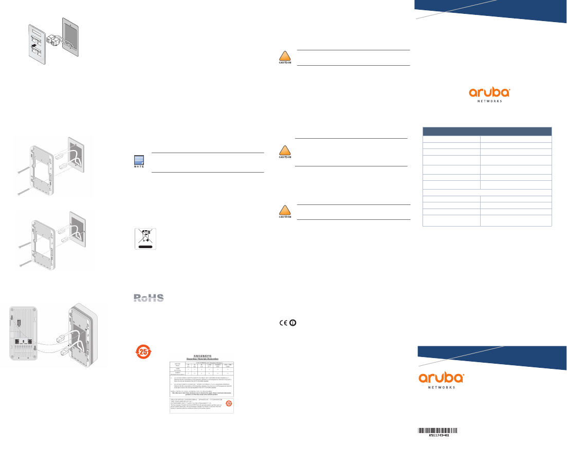
Installing the AP
The AP-205H is designed to mount into a variety of electrical gang boxes.
1. Begin by removing the existing data wall plate (if applicable).
!
To meet regulatory restrictions, this access point must be
professionally installed.
The Aruba AP-205H requires ArubaOS 6.4.3 or later.
Inform your supplier if there are any incorrect, missing, or damaged
parts. If possible, retain the carton, including the original packing
materials. Use these materials to repack and return the unit to the
supplier if needed.
Table 1
LED Color/State Meaning
System Status Off AP powered off, or LED
switched to ‘off mode’
Red Error condition
Green - Flashing AP booting
Green - Solid AP ready
PSE Off AP powered off, or PoE
capability disabled
Green - Solid AP supplying PoE power
Red PoE sourcing error
condition
For more information LED modes, refer to the ArubaOS User Guide.
Hot-plug operation is not recommended for the console port.
The USB interface is disabled when the AP-205H is powered from 802.3af
PoE.
Table 2
Power Source Restrictions Maximum Power Levels
DC (AP-AC-48V36) None 150mA, 275mA, 475mA, 600mA
Basic 802.3af USB, Poe-PSE disabled 8W, 13.5W, N/A, N/A
High-Power PoE USB, PoE-PSE enabled 8W, 14W, 24W, N/A
If both POE and DC power are available, the AP will use PoE.
!
FCC Statement: Improper termination of access points installed in
the United States configured to non-US model controllers will be in
violation of the FCC grant of equipment authorization. Any such willful
or intentional violation may result in a requirement by the FCC for
immediate termination of operation and may be subject to forfeiture
(47 CFR 1.80).
!
EU Statement:
Lower power radio LAN product operating in 2.4 GHz and 5 GHz
bands. Please refer to the ArubaOS User Guide for details on
restrictions.
Produit réseau local radio basse puissance operant dans la bande
fréquence 2.4 GHz et 5 GHz. Merci de vous referrer au ArubaOS User
Guide pour les details des restrictions.
Low Power FunkLAN Produkt, das im 2.4 GHz und im 5 GHz Band
arbeitet. Weitere Informationen bezlüglich Einschränkungen finden
Sie im ArubaOS User Guide.
Apparati Radio LAN a bassa Potenza, operanti a 2.4 GHz e 5 GHz.
Fare riferimento alla ArubaOS User Guide per avere informazioni
detagliate sulle restrizioni.
It is important that you verify the items listed under AP Pre-Installation
Checklist before you attempt to set up and install an AP-205H.
Aruba Networks, Inc., in compliance with governmental requirements, has
designed the AP-205H access points so that only authorized network
administrators can change the settings. For more information about AP
configuration, refer to the ArubaOS Quick Start Guide and ArubaOS User
Guide.
!
Access points are radio transmission devices and as such are subject to
governmental regulation. Network administrators responsible for the
configuration and operation of access points must comply with local
broadcast regulations. Specifically, access points must use channel
assignments appropriate to the location in which the access point will be
used.
Service to all Aruba Networks products should be performed by trained
service personnel only.
Aruba AP-205H Wireless
Access Point
Installation Guide
www.arubanetworks.com
1344 Crossman Avenue
Sunnyvale, California 94089
Phone: 408.227.4500
Fax 408.227.4550
Aruba AP-205H Wireless Access Point | Installation Guide
Part Number 0511734-01 | March 2015
Contacting Aruba Networks
Web Support
Main Site http://www.arubanetworks.com
Support Site https://support.arubanetworks.com
Airheads Social Forums and Knowledge Base community.arubanetworks.com
North American Telephone 1-800-943-4526 (Toll Free)
1-408-754-1200
International Telephones arubanetworks.com/support-services/aruba-support-
program/contact-support/
Software Licensing Site licensing.arubanetworks.com/login.php
Wireless Security Incident
Response Team (WSIRT) arubanetworks.com/support/wsirt.php
Support Email Addresses
Americas and APAC support@arubanetworks.com
EMEA emea.support@arubanetworks.com
Americas and APAC Support Email support@arubanetworks.com
WSIRT Email
Please email details of any security
problem found in an Aruba product.
wsirt@arubanetworks.com
Copyright
© 2015 Aruba Networks, Inc. AirWave®, Aruba Networks®, Aruba Mobility Management System®, Bluescanner,
For Wireless That Works®, Mobile Edge Architecture, People Move. Networks Must Follow., RFProtect®, The All
Wireless Workplace Is Now Open For Business, and The Mobile Edge Company® are trademarks of Aruba
Networks, Inc. All rights reserved. All other trademarks are the property of their respective owners.
Open Source Code
Certain Aruba products include Open Source software code developed by third parties, including software code
subject to the GNU General Public License ("GPL"), GNU Lesser General Public License ("LGPL"), or other Open
Source Licenses. The Open Source code used can be found at this site:
http://www.arubanetworks.com/open_source
Legal Notice
The use of Aruba Networks, Inc. switching platforms and software, by all individuals or corporations, to terminate
other vendors' VPN client devices constitutes complete acceptance of liability by that individual or corporation for
this action and indemnifies, in full, Aruba Networks, Inc. from any and all legal actions that might be taken against
it with respect to infringement of copyright on behalf of those vendors.
Warranty
This hardware product is protected by an Aruba warranty. For details, see Aruba Networks standard warranty
terms and conditions.
Figure 5 Removing Wall Plate (US Single Gang Outlet Box Shown)
2. Remove any existing RJ45 connectors (typically snap-in) or cut/remove the UTP cable.
3. Use a short Ethernet cable (sold separately) to connect the E0 port to an RJ45
connector or crimp an RJ45 plug (not supplied) on the cable and insert in the E0 port.
Do the same for the PT port, if used.
4. Align the mounting holes of the AP-205H mounting bracket with mounting holes in you
gang box as shown in Figure 6 and Figure 7. For worldwide single gang outlet box, the
mounting bracket has two sets of mounting holes to meet the individual installation
position requirement. See Figure 7 for details.
The applicable standards for the wall boxes are:
IEC 60670-1, GB17466, BS4662 and DIN49073 for Worldwide
ANSI/NEMA OS 1 and OS 2 for US
5. Insert the two included machine screws and tighten them to secure the mounting
bracket.
Figure 6 Bracket to Gang Box (US Single Gang Outlet Box Shown)
Figure 7 Bracket to Gang Box (Worldwide Single Gang Outlet Box Shown)
6. Connect any required cables to the rear of the AP-205H.
7. Align the mounting posts on the back of your AP-205H with the corresponding
mounting holes on the mounting bracket as shown in Figure 8.
8. Push the AP against the holes and downward until the posts engage the slots at the top
of the mounting holes.
Figure 8 AP-205H to Bracket
9. Once the AP is fastened onto the bracket, insert the Torx Security Screw into the hole
located in the upper-right edge of the access point and tighten.
10. If not using PoE, connect the AC-DC power adapter (sold separately) to the DC power
socket located on the bottom of the AP-205H.
Verifying Post-Installation Connectivity
The integrated LED on the AP can be used to verify that the AP is receiving power and
initializing successfully (see Table 1). Refer to the ArubaOS Quick Start Guide for further
details on verifying post-installation network connectivity.
Configuring the AP-205H
AP Provisioning/Reprovisioning
Provisioning parameters are unique to each AP. These local AP parameters are initially
configured on the controller which are then pushed out to the AP and stored on the AP
itself. Aruba recommends that provisioning settings be configured via the ArubaOS Web
UI only. Refer to the ArubaOS User Guide for complete details.
AP Configuration
Configuration parameters are network or controller specific and are configured and
stored on the controller. Network configuration settings are pushed out to the AP(s) but
remain stored on the controller.
Configuration settings can be configured via the ArubaOS Web UI or ArubaOS CLI. Refer
to ArubaOS User Guide for details.
Product Specifications
Electrical
Ethernet:
1 x 10/100/1000Base-T auto-sensing Ethernet RJ-45 Interface (E0-E3)
1 x passive RJ-45 pass-through interface
MDI/MDX
IEEE 802.3 (10Base-T), IEEE 802.3u (100Base-T). IEEE 802.3ab (1000Base-T)
Power over Ethernet (IEEE 802.3af compliant), 48V DC (nominal) and 56V DC
(maximum)/350mA (see Figure 4 for pin configuration)
Power:
48VDC power interface, supports powering through an AC-to-DC power adapter
POE support on Ethernet ports: 802.3af-compliant POE sourcing device
For additional specifications on this product, please refer to the data sheet. The data sheet
can be found at www.arubanetworks.com.
Proper Disposal of Aruba Equipment
Dispose of Aruba products per local regulation. For the most current information about
Global Environmental Compliance and Aruba products, see our website at
www.arubanetworks.com.
Waste of Electrical and Electronic Equipment
Aruba products at end of life are subject to separate collection and
treatment in the EU Member States, Norway, and Switzerland and
therefore are marked with the symbol shown at the left (crossed-out
wheelie bin). The treatment applied at end of life of these products in
these countries shall comply with the applicable national laws of
countries implementing Directive 2002/96EC on Waste of Electrical
and Electronic Equipment (WEEE).
India RoHS
This product complies with RoHS requirements as prescribed by E-Waste (Management &
Handling) Rules, governed by the Ministry of Environment & Forests, Government of
India.
European Union RoHS
Aruba products also comply with the EU Restriction of Hazardous
Substances Directive 2011/65/EC (RoHS). EU RoHS restricts the
use of specific hazardous materials in the manufacture of
electrical and electronic equipment. Specifically, restricted
materials under the RoHS Directive are Lead (including Solder used in printed circuit
assemblies), Cadmium, Mercury, Hexavalent Chromium, and Bromine. Some Aruba
products are subject to the exemptions listed in RoHS Directive Annex 7 (Lead in solder
used in printed circuit assemblies). Products and packaging will be marked with the
“RoHS” label shown at the left indicating conformance to this directive.
China RoHS
Aruba products also comply with China environmental declaration
requirements and are labeled with the “EFUP 25” label shown at the left.
Safety and Regulatory Compliance
Aruba Networks provides a multi-language document that contains country-specific
restrictions and additional safety and regulatory information for all Aruba access points.
This document can be viewed or downloaded from the following location:
www.arubanetworks.com/safety_addendum
Regulatory Model Name
The regulatory model name of AP-205H is APINH205.
FCC
This equipment generates, uses and can radiate radio frequency energy, and, if not
installed and used in accordance with the manufacturer’s instructions may cause harmful
interference to other devices in the vicinity. However, there is no guarantee that
interference will not occur in a particular installation. If this equipment causes
interference with other devices, which may be determined by turning the equipment off
and on, the user is encouraged to try and correct the interference by one or more of the
following measures:
Reorient or relocate the device receiving the interference.
Increase the separation between the equipment.
Connect the equipment into an outlet on a circuit different from that to which the
other device(s) are connected.
Consult the manufacturer or field service technician for help.
The protection against electric shock is Class ll.
Equipment not suitable for use in the presence of flammable mixtures.
FCC Class B Part 15
This device complies with Part 15 of the Federal Communications Commission (FCC)
Rules. Operation is subject to the following two conditions:
1. This device may not cause harmful interference.
2. This device must accept any interference received, including interference that may
cause undesired operation.
This equipment has been tested and found to comply with the limits for a Class B digital
device, pursuant to Part 15 of the FCC Rules. This equipment generates, uses and can
radiate radio frequency energy and, if not installed and used in accordance with the
manufacturer’s instructions, may cause interference harmful to radio communications.
If this equipment does cause interference, which can be determined by turning the
equipment off and on, the user is encouraged to try to correct the interference by one or
more of the following measures:
Reorient or relocate the receiving antenna.
Increase the separation between the equipment and receiver.
Connect the equipment to an outlet on a circuit different from that to which the
receiver is connected.
Consult the dealer or an experienced radio or TV technician for help.
Complies with the Class B limits for radio noise emissions as set out in the interference-
causing equipment standard entitled “Digital Apparatus,” ICES-003 of Industry Canada.
Cet apareil numerique de la classe B respecte toutes les exigencies du Reglement sur le
materiel brouilleur du Canada.
Users are advised that high power Radars are allocated as primary users of the bands
5250-5350 MHz and 5650-5850 MHz and these Radars could cause interference and/or
damage to Licensed Exempt WLAN devices.
EU Regulatory Conformance
This product is CE marked according to the provisions of the R & TTE
Directive (1999/5/EC) - CE(!). Aruba Networks Inc., hereby declares that the APINH205
device model is in compliance with the essential requirements and other relevant
provisions of Directive 1999/5/EC -CE(!)
The Declaration of Conformity made under Directive 1999/5/EC is available for viewing at
the following location: http://support.arubanetworks.com
Users are advised that high power Radars are allocated as primary users of the bands
5250-5350 MHz and 5650-5850 MHz and these Radars could cause interference and/or
damage to Licensed Exempt WLAN devices.
Canadian Statement
Under Industry Canada regulations, this radio transmitter may only operate using an
antenna of a type and maximum (or lesser) gain approved for the transmitter by Industry
Canada. To reduce potential radio interference to other users, the antenna type and its
gain should be so chosen that the equivalent isotropically radiated power (e.i.r.p.) is not
more than that necessary for successful communication.
This device complies with Industry Canada licence-exempt RSS standard(s).
Operation is subject to the following two conditions: (1) this device may not cause
interference, and (2) this device must accept any interference, including interference that
may cause undesired operation of the device.
Déclaration d’Industrie Canada
1. Conformément aux réglementations d’Industrie Canada, cet émetteur-récepteur radio doit être
utilisé uniquement avec une antenne dont le type et le gain maximal doivent être approuvés par
Industrie Canada. Pour réduire les interférences radio potentielles, le type d’antenne et son gain
If a power adapter other than the one provided by Aruba Networks is used
in the US or Canada, it should be NRTL Listed, with an output rated 12
VDC, minimum 1.25A, marked “LPS” and “Class 2”, and suitable for
plugging into a standard power receptacle in the US and Canada.
!
Aruba access points must be installed by a professional installer. The
professional installer is responsible for ensuring that grounding is available
and it meets applicable local and national electrical codes.
!
RF Radiation Exposure Statement: This equipment complies with FCC
RF radiation exposure limits. This equipment should be installed and
operated with a minimum distance of 7.87 inches (20cm) between the
radiator and your body for 2.4 GHz and 5 GHz operations. This transmitter
must not be co-located or operating in conjunction with any other antenna
or transmitter.
!
Changes or modifications to this unit not expressly approved by the party
responsible for compliance could void the user’s authority to operate this
equipment.

doivent être choisis de façon à ce que la puissance isotrope rayonnée équivalente (PIRE) ne
dépasse pas les valeurs nécessaires à une communication efficace.
Ce périphérique est conforme aux règlements RSS exempts de licence d’Industrie Canada.
L’utilisation de ce périphérique est soumise aux deux conditions suivantes : (1) ce périphérique ne doit pas
provoquer d’interférences, et (2) ce périphérique doit accepter toute interférence, y compris les interférences
susceptibles de provoquer un dysfonctionnement.
Medical
1. Equipment not suitable for use in the presence of flammable mixtures.
2. Connect to only IEC 60950-1 or IEC 60601-1 3rd edition certified products and power sources.
The end user is responsible for the resulting medical system complies with the requirements of
IEC 60601-1 3rd edition.
3. Wipe with a dry cloth, no additional maintenance required.
4. No serviceable parts, the unit must be sent back to the manufacturer for repair.
5. No modifications are allowed without Aruba approval.
䫔⋩Ḵ㡅
ˢˢ䴻✳⺷娵嫱⎰㟤ᷳỶ≇䌯⮬柣暣㨇炻朆䴻姙⎗炻℔⎠ˣ⓮嘇ㆾἧ䓐侭⛯ᶵ⼿㑭冒嬲㚜柣䌯ˣ≈
⣏≇䌯ㆾ嬲㚜⍇姕妰ᷳ䈡⿏⍲≇傥ˤ
䫔⋩⚃㡅
ˢˢỶ≇䌯⮬柣暣㨇ᷳἧ䓐ᶵ⼿⼙枧梃凒⬱ℐ⍲⸚㒦⎰㱽忂ᾉ烊䴻䘤䎦㚱
⸚㒦䎦尉㗪炻ㅱ䩳⌛ 䓐炻᷎㓡┬军䃉⸚㒦㗪㕡⼿两临ἧ䓐ˤ
ˢˢ⇵枭⎰㱽忂ᾉ炻㊯ὅ暣ᾉ㱽夷⭂ἄ㤕ᷳ䃉䶂暣忂ᾉˤ
ˢˢỶ≇䌯⮬柣暣㨇枰⽵⍿⎰㱽忂ᾉㆾⶍ㤕ˣ䥹⬠⍲慓䗪䓐暣㲊廣⮬⿏暣
ġġġġ㨇姕⁁ᷳ⸚㒦ˤ
For additional compliance information, pull down on the adhesive accordion
sticker located on the back of the access point. This sticker may be folded
back and reused once opened.