Hewlett Packard Enterprise APINR15515P Wireless Access Point User Manual Aruba RAP 155 155P Installation Guide
Aruba Networks, Inc. Wireless Access Point Aruba RAP 155 155P Installation Guide
Contents
- 1. Installation Guide
- 2. Installation
Installation Guide
Aruba RAP-155 / RAP-155P Remote Access Point
Installation Guide
The Aruba RAP-155 and RAP-155P are dual-radio, dual-band wireless access
points (AP) that offer wired and wireless network access, zero-touch
provisioning, identity-based access control, policy based forwarding, air
monitoring, and wireless intrusion protection across the 2.4 GHz and 5 GHz
(802.11a/b/g and 802.11n) bands.
The Aruba RAP-155 and RAP-155P ship with the Aruba Instant software.
Therefore, out of the box, the Aruba RAP-155 and RAP-155P operate as a Virtual
Controller (VC) or an Instant AP. However, the Aruba RAP-155 and RAP-155P
can be converted to operate as a Remote AP (RAP). For information about the
IAP to RAP conversion, see RAP Conversion.
The Aruba RAP-155 and RAP-155P provide the following capabilities:
Wireless transceiver
Protocol-independent networking functionality
IEEE 802.11 a/b/g/n operation as a wireless access point
IEEE 802.11 a/b/g/n operation as a wireless air monitor
Compatibility with IEEE 802.3af and IEEE 802.3at PoE
Package Contents
1x Aruba RAP-155 or RAP-155P Access Point
1x Stand
1x Installation Guide (this document)
1x Aruba Instant Quick Start Guide
1x RJ-45 Ethernet Cable
1x 12V Power Adapter, power cord included (RAP-155 only)
1x 54V Power Adapter (RAP-155P only)
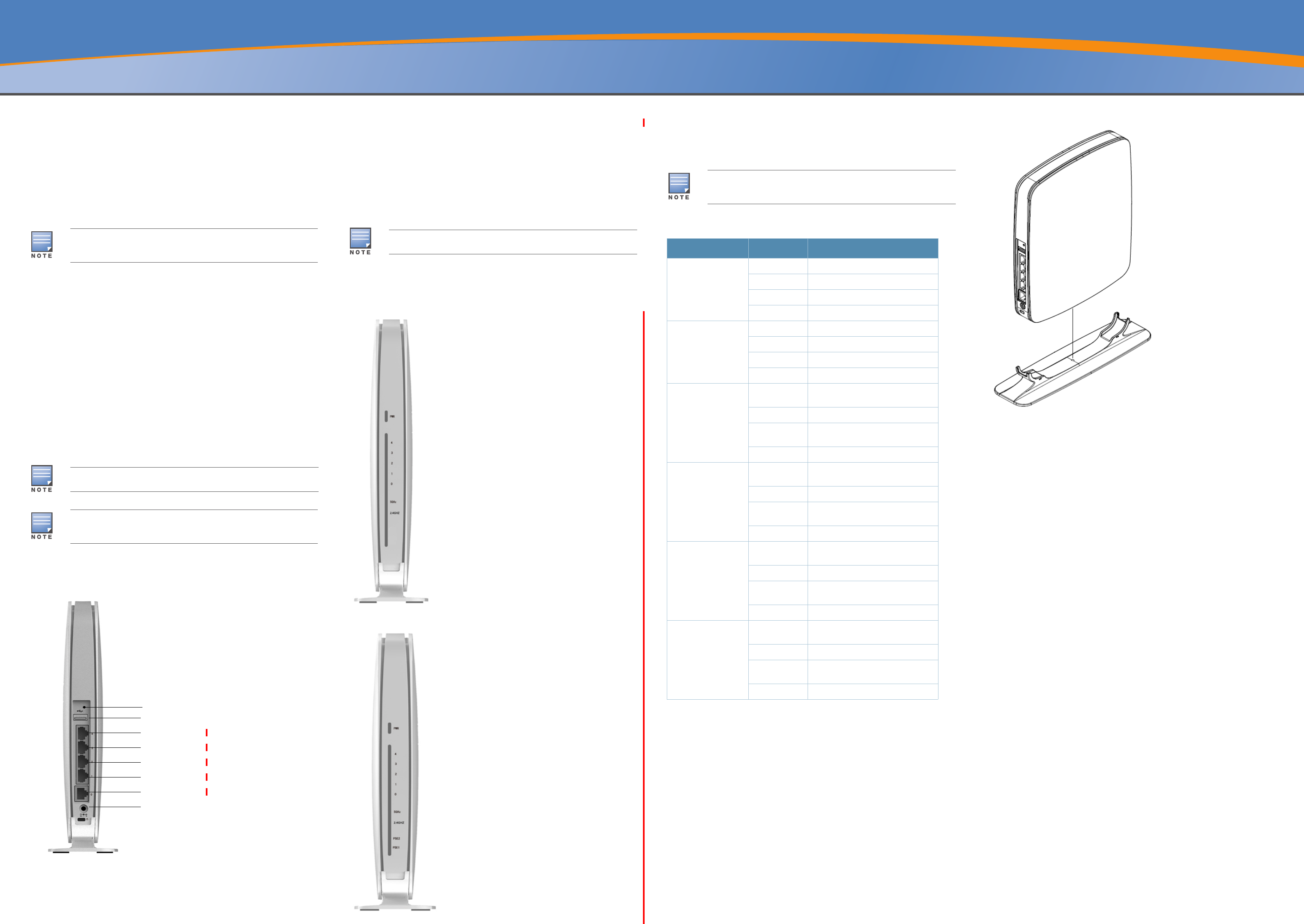
RAP-155 and RAP-155P Overview
Figure 1 Rear View
10/100/1000 Base-T Ethernet Ports
The RAP-155 or RAP-155P has five 10/100/1000Base-T (RJ-45) Ethernet ports for
wired network connectivity. E0 is an uplink port and E1-E4 are downlink ports.
E0: WAN port
E1: LAN port
E2: LAN port
E3: LAN port
E4: LAN port
On the RAP-155P, port E1 and E2 have PoE power sourcing capability (PSE) to
supply power to two 802.3af powered device (class 0-4) on E1 and E2 port or one
802.3at powered device on either E1 or E2 port.
DC IN (Power Socket)
The RAP-155 or RAP-155P power adapter (included) connects to the DC IN port.
The RAP-155 or RAP-155P does not have an On/Off switch. The device turns on
when the power adapter is attached and plugged into a power outlet. The device
turns off when you disconnect the power adapter from the power source
(outlet).
USB Port
The RAP-155 or RAP-155P is equipped with a USB port to support cellular
modems.
Figure 2 Front View of RAP-155
Figure 3 Front View of RAP-155P
Serial Console Port
The serial console port is located at the bottom of RAP-155 or RAP-155P and
closed by a rubber insert when not in use. To use this port for troubleshooting,
remove the rubber insert and connect the serial adapter cable to the port.
LEDs
Reset Button
The RAP-155 and RAP-155P are equipped with a reset button, that when pushed,
resets the device to factory default settings. The reset button is located on the
rear of the device and is recessed in a small, round hole.
To reset the RAP-155 and RAP-155P, insert a small, narrow object, such as a pin
or paperclip, into the hole and press and hold the button for 5-10 seconds while
powering on the RAP-155 and RAP-155P. This will return the device to factory
default settings.
RAP-155 and RAP-155P Installation
Tabletop Mounting
The RAP-155 and RAP-155P ship with a stand to use on flat (i.e. table top)
surfaces. Place the RAP-155 and RAP-155P in the stand (see Figure 4) and place
the stand on a flat, level surface.
Figure 4 Stand Installation
Connecting the Required Cables
The RAP-155 or RAP-155P must be connected to a network device that has
access to the Internet, such as a router or modem. To complete the installation
of the RAP-155 or RAP-155P:
1. Connect one end of the provided RJ-45 cable to port E0 on the RAP-155 or
RAP-155P.
2. Connect the other end of the RJ-45 cable to a free RJ-45 port on your modem
or router.
3. Attach the provided power adapter to the DC IN port on the RAP-155 or RAP-
155P.
4. Connect the other end of the power adapter to a power outlet.
The RAP-155 or RAP-155P is now powered on. To verify this, ensure that the
PWR LED is solid green.
Verifying Successful Installation
Once the RAP-155/RAP-155P’s PWR LED has come up, the device will take 2 to 3
minutes to complete the boot cycle. Once the boot cycle is complete, you can
connect to your company or corporate network.
RAP Conversion
If your network administrator has instructed you to convert the RAP-155 or RAP-
155P to work in RAP mode, follow the process below to complete the RAP
conversion.
1. Power up the RAP-155 or RAP-155P.
2. Connect to Instant SSID.
3. Login to the RAP-155 or RAP-155P by navigating to http://
instant.arubanetworks.com and login to the Instant UI. The default username is
admin and the default password is admin. See the included Aruba Instant
Quick Start Guide for more information.
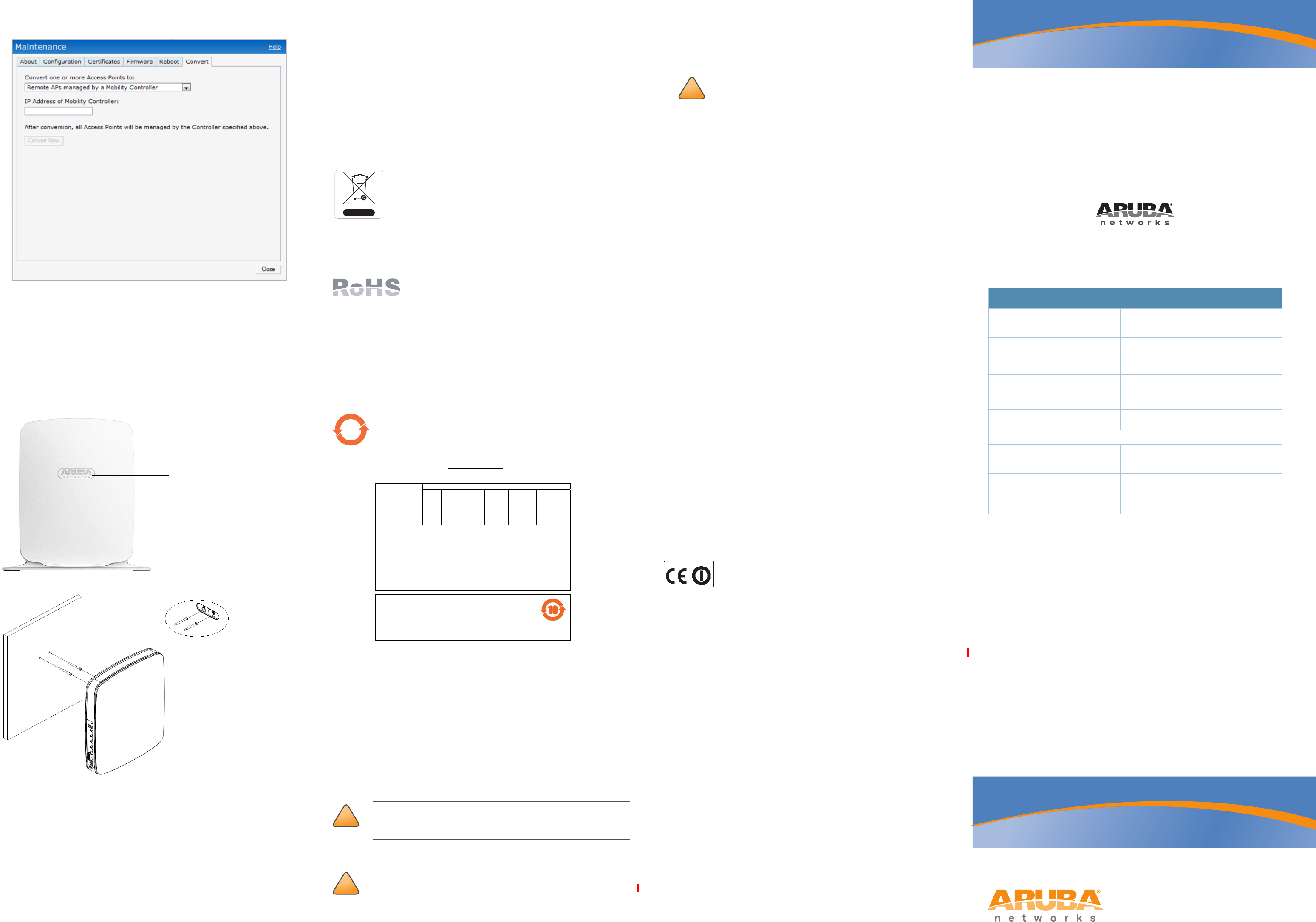
4. Navigate to the Maintenance tab in the top right.
5. Click on the Convert tab.
6. Select Remote APs managed by a Mobility Controller from the drop
down menu.
7. Enter the IP address of the controller. This is provided by your network
administrator.
8. Click Convert Now to complete the conversion (see Figure 5).
9. The RAP-155 or RAP-155P will reboot and begin operating in RAP mode.
The Aruba RAP-155 and RAP-155P require Aruba Instant 3.3 or higher
version when deployed as an Instant AP and ArubaOS 6.3 or higher version
when deployed in conjunction with a Mobility Controller.
The 54V power adapter that ships with the RAP-155P does not come with a
country specific power cord. This cord must be ordered separately.
Inform your supplier if there are any incorrect, missing, or damaged parts. If
possible, retain the carton, including the original packing materials. Use
them to repack the product in case there is a need to return it.
Reset button
USB port
E4 (LAN port)
E3 (LAN port)
E2 (LAN port)
E1 (LAN port)
E0 (WAN port)
DC IN (Power)
The RAP-155 ships with a 12V power supply and the RAP-155P ships with
a 54V power supply. These power supplies are not interchangeable.
The RAP-155 or RAP-155P does not ship with a serial adapter cable. This
cable is available as accessory with the part number AP-CBL-SER and
should be ordered separately.
LED Mode Status
PWR On-Green Device Ready
Flashing-Green Device booting - not ready
Red Initial power-up condition
Off No power
Ports (E0, E1, E2, E3,
E4)
On-Green 1000 Mbps link established
Off No Ethernet link
On-Amber 10/100 Mbps link established
Flashing Ethernet activity
RF0 (Radio 0, 5GHz,
802.11a/n)
On-Green 5GHz radio enabled in HT WLAN
mode
Flashing 5GHz Air monitor
On-Amber 5GHz radio enabled in non-HT WLAN
mode
Off 5GHz radio disabled
RF1 (Radio 1, 2.4GHz,
802.11b/g/n)
On-Green 2.4GHz radio enabled in HT WLAN
mode
Flashing 2.4GHz Air monitor
On-Amber 2.4GHz radio enabled in non-HT
WLAN mode
Off 2.4GHz radio disabled
PSE1 (RAP-155P only) On-Green Port1 sourcing POE power to an
802.3at powered device.
Flashing Port1 PoE sourcing error condition
On-Green Port1 sourcing POE power to an
802.3af powered device.
Off No PoE power sourcing on port1.
PSE2 (RAP-155P only) On-Green Port2 sourcing POE power to an
802.3at powered device.
Flashing Port2 PoE sourcing error condition
On-Amber Port2 sourcing POE power to an
802.3af powered device.
Off No PoE power sourcing on port2.
Aruba RAP-155 / RAP-155P
Remote Access Point
Installation Guide
www.arubanetworks.com
1344 Crossman Avenue
Sunnyvale, California 94089
Phone: 408.227.4500
Fax 408.227.4550
Aruba RAP-155 / RAP-155P Remote Access Point | Installation Guide
Part Number 0511212-01 | March 2013
Contacting Aruba Networks
Web Support
Main Site http://www.arubanetworks.com
Support Site https://support.arubanetworks.com
Airheads Social Forums and Knowledge Base community.arubanetworks.com
North American Telephone 1-800-943-4526 (Toll Free)
1-408-754-1200
International Telephones arubanetworks.com/support-services/aruba-support-
program/contact-support/
Software Licensing Site licensing.arubanetworks.com/login.php
Wireless Security Incident
Response Team (WSIRT)
arubanetworks.com/support/wsirt.php
Support Email Addresses
Americas and APAC support@arubanetworks.com
EMEA emea.support@arubanetworks.com
Americas and APAC Support Email support@arubanetworks.com
WSIRT Email
Please email details of any security
problem found in an Aruba product.
wsirt@arubanetworks.com
Copyright
© 2013 Aruba Networks, Inc. AirWave®, Aruba Networks®, Aruba Mobility Management System®, Bluescanner,
For Wireless That Works®, Mobile Edge Architecture, People Move. Networks Must Follow., RFProtect®, The All
Wireless Workplace Is Now Open For Business, and The Mobile Edge Company® are trademarks of Aruba
Networks, Inc. All rights reserved. All other trademarks are the property of their respective owners.
Open Source Code
Certain Aruba products include Open Source software code developed by third parties, including software code
subject to the GNU General Public License ("GPL"), GNU Lesser General Public License ("LGPL"), or other Open
Source Licenses. The Open Source code used can be found at this site:
http://www.arubanetworks.com/open_source
Legal Notice
The use of Aruba Networks, Inc. switching platforms and software, by all individuals or corporations, to terminate
other vendors' VPN client devices constitutes complete acceptance of liability by that individual or corporation for
this action and indemnifies, in full, Aruba Networks, Inc. from any and all legal actions that might be taken against
it with respect to infringement of copyright on behalf of those vendors.
Warranty
This hardware product is protected by the standard Aruba warranty of one year parts/labor. For more information,
refer to the ARUBACARE SERVICE AND SUPPORT TERMS AND CONDITIONS.
Altering this device (such as painting it) voids the warranty.
Figure 5 IAP-RAP Conversion over the Internet
Wall Mounting Instructions
The two mount holes (the center-to-center distance is 26mm) are covered by the
plastic plate with Aruba logo on the back of the RAP-155 and RAP-155P as shown
in Figure 6. The mount holes can be used to attach the device upright to an
indoor wall as shown in Figure 7. To install RAP-155 and RAP-155P on a wall:
1. At the mounting location, install two screw on the wall, 26mm apart
2. Remove the plastic plate, align the mount holes over the screws and slide the
unit into place.
Figure 6 Mount Holes on the Back of RAP-155/RAP-155P
Figure 7 Mounting RAP-155/RAP-155P on a Wall
Product Specifications
Electrical
Ethernet:
5 x 10/100/1000BASE-T auto-sensing Ethernet RJ-45 Interfaces
MDI/MDX
10/100/1000BASE-T are IEEE 802.3 and EEE 802.3u compliant.
Power - RAP-155:
12 VDC power interface, supports powering through an AC-to-DC power
adapter
Power - RAP-155P:
54 VDC power interface, supports powering through an AC-to-DC power
adapter
PoE feature support (RAP-155P only)
Supply PoE power to up to two IEEE 802.3af powered device (class 0-4)
on E1 and E2 port (the output power is 13 watts at each port)
Supply PoE power to one IEEE 802.3at powered device on either E1 or E2
port (the output power is 25.5 watts)
For additional specifications on this product, please refer to the data sheet. The
data sheet can be found at www.arubanetworks.com.
Proper Disposal of Aruba Equipment
For the most current information about Global Environmental Compliance and
Aruba products, see our website at www.arubanetworks.com.
Waste of Electrical and Electronic Equipment
Aruba products at end of life are subject to separate collection
and treatment in the EU Member States, Norway, and
Switzerland and therefore are marked with the symbol shown at
the left (crossed-out wheelie bin). The treatment applied at end
of life of these products in these countries shall comply with the
applicable national laws of countries implementing Directive
2002/96EC on Waste of Electrical and Electronic Equipment (WEEE).
European Union RoHS
Aruba products also comply with the EU Restriction of
Hazardous Substances Directive 2002/95/EC (RoHS). EU
RoHS restricts the use of specific hazardous materials in
the manufacture of electrical and electronic equipment. Specifically, restricted
materials under the RoHS Directive are Lead (including Solder used in printed
circuit assemblies), Cadmium, Mercury, Hexavalent Chromium, and Bromine.
Some Aruba products are subject to the exemptions listed in RoHS Directive
Annex 7 (Lead in solder used in printed circuit assemblies). Products and
packaging will be marked with the “RoHS” label shown at the left indicating
conformance to this Directive.
China RoHS
Aruba products also comply with China environmental declaration
requirements and are labeled with the “EFUP 10” label shown at the
left.
Safety and Regulatory Compliance
Aruba Networks provides a multi-language document that contains country-
specific restrictions and additional safety and regulatory information for all
Aruba access points. This document can be viewed or downloaded from the
following location: www.arubanetworks.com/safety_addendum
Regulatory Model Names
The following regulatory model names apply to the RAP-155 and RAP-155P:
RAP-155: APINR155
RAP-155P: APINR15P
EMC Compliance and Warning Statement
FCC Class B Part 15
This device complies with Part 15 of the Federal Communications Commission
(FCC) Rules. Operation is subject to the following two conditions:
This device may not cause harmful interference.
This device must accept any interference received, including interference that
may cause undesired operation.
The device has been found to be compliant to the requirements set forth in CFR
47 Sections 2.1091 for an uncontrolled environment. The antenna(s) used for this
transmitter must be installed to provide a separation distance of at least 20 cm
from all persons and must not be co-located or operating in conjunction with any
other antenna or transmitter.
This equipment has been tested and found to comply with the limits for a Class B
digital device, pursuant to Part 15 of the FCC Rules. This equipment generates,
uses and can radiate radio frequency energy and, if not installed and used in
accordance with the manufacturer’s instructions, may cause interference
harmful to radio communications.
If this equipment does cause interference, which can be determined by turning
the equipment off and on, the user is encouraged to try to correct the
interference by one or more of the following measures:
Reorient or relocate the receiving antenna.
Increase the separation between the equipment and receiver.
Connect the equipment to an outlet on a circuit different from that to which
the receiver is connected.
Consult the dealer or an experienced radio or TV technician for help.
Complies with the Class B limits for radio noise emissions as set out in the
interference-causing equipment standard entitled “Digital Apparatus,” ICES-003
of Industry Canada.
Cet apareil numerique de la classe B respecte toutes les exigencies du Reglement
sur le materiel brouilleur du Canada.
L ‘ utilisation de ce dispositif est autorisée seulement aux conditions suivantes :
(1) il ne doit pas produire de brouillage et (2) l’ utilisateur du dispositif doit étre
prêt à accepter tout brouillage radioélectrique reçu, même si ce brouillage est
susceptible de compromettre le fonctionnement du dispositif.
Le présent appareil est conforme aux normes CNR d’industrie Canada
applicables aux appareils radio exempts licence. L’exploitation est autorisée aux
deux conditions suivantes:
1. L’appareil ne doit produire de brouillage, et
2. L’utilisateur de l’appareil doit accepter tout brouillage radioélectrique subi,
même si le brouillage est susceptible d’en compromettre le fonctionnement.
EU Regulatory Conformance
This product is CE marked according to the provisions of the R &
TTE Directive (99/5/EC) - CE(!). Aruba Networks Inc., hereby
declares that the APINR155 / APINR15P device models are in compliance with
the essential requirements and other relevant provisions of Directive 1999/5/EC -
CE(!)
The Declaration of Conformity made under Directive 1999/5/EC is available for
viewing at the following location: http://support.arubanetworks.com
Two mount holes
located under this
plastic plate
!
CAUTION
Aruba access points must be installed by a professional installer. The
professional installer is responsible for ensuring that grounding is
available and it meets applicable local and national electrical codes.
!
CAUTION
RF Radiation Exposure Statement: This equipment complies with FCC
RF radiation exposure limits. This equipment should be installed and
operated with a minimum distance of 35cm between the radiator and
your body. This transmitter must not be co-located or operating in
conjunction with any other antenna or transmitter.
10
᳝↦᳝ᆇ⠽䋼ໄᯢ
Hazardous Materials Declaration
᳝↦᳝ᆇ⠽䋼ܗ㋴(Hazardous Substance)
䚼ӊৡ⿄
(Parts) 䪙
3E
∲
+J
䬝
&G
݁Ӌ䫀
&U
⒈㘨㣃
3%%
⒈Ѡ㣃䝮
3%'(
⬉䏃ᵓ
(PCA Boards) hƻ ƻ ƻ ƻ ƻ
ᴎẄ㒘ӊ
(Mechanical Sub-Assemblies) hƻ ƻ ƻ ƻ ƻ
ƻ˖ 㸼⼎䆹᳝↦᳝ᆇ⠽䋼䆹䚼ӊ᠔᳝ഛ䋼ᴤ᭭Ёⱘ䞣ഛ SJ/T11363-2006 ᷛޚ㾘ᅮⱘ䰤䞣㽕∖ҹϟDŽ
Indicates that the concentration of the hazardous substance in all homogeneous materials in the parts is
below the relevant threshold of the SJ/T11363-2006 standard.
h˖ 㸼⼎䆹᳝↦᳝ᆇ⠽䋼㟇ᇥ䆹䚼ӊⱘᶤϔഛ䋼ᴤ᭭Ёⱘ䞣䍙ߎ6-7ᷛޚ㾘ᅮⱘ䰤䞣㽕∖DŽ
Indicates that the concentration of the hazardous substance of at least one of all homogeneous materials
in the parts is above the relevant threshold of the SJ/T11363-2006 standard.
ᇍ䫔ଂП᮹ⱘ᠔ଂѻકᴀ㸼ᰒ⼎կᑨ䫒ⱘ⬉ᄤֵᙃѻકৃ㛑ࣙ䖭ѯ⠽䋼DŽ
This table shows where these substances may be found in the supply chain of electronic information
products, as of the date of sale of the enclosed product.
ℸᷛᖫЎ䩜ᇍ᠔⍝ঞѻકⱘ⦃ֱՓ⫼ᳳᷛᖫᶤѯ䳊䚼ӊӮ᳝ϔϾϡৠⱘ⦃ֱՓ⫼ᳳ
՟བ⬉∴ऩܗഫ䌈݊ѻકϞ
ℸ⦃ֱՓ⫼ᳳ䰤া䗖⫼ѢѻકᰃѻકݠЁ᠔㾘ᅮⱘᴵӊϟᎹ
The Environment- Friendly Use Period (EFUP) for all enclosed products and their parts are
per the symbol shown here. The Environment- Friendly Use Period is valid only when the
product is operated under the conditions defined in the product manual.
!
CAUTION
Changes or modifications to this unit not expressly approved by the
party responsible for compliance could void the user’s authority to
operate this equipment.