Hewlett Packard Enterprise ARUBA6061 802.11.a/.b/.g User Manual
Aruba Networks, Inc. 802.11.a/.b/.g
UserManual.wiki
>
Hewlett Packard Enterprise
>
ARUBA6061 User Manual
>
User Manual Part 1
Contents
1.
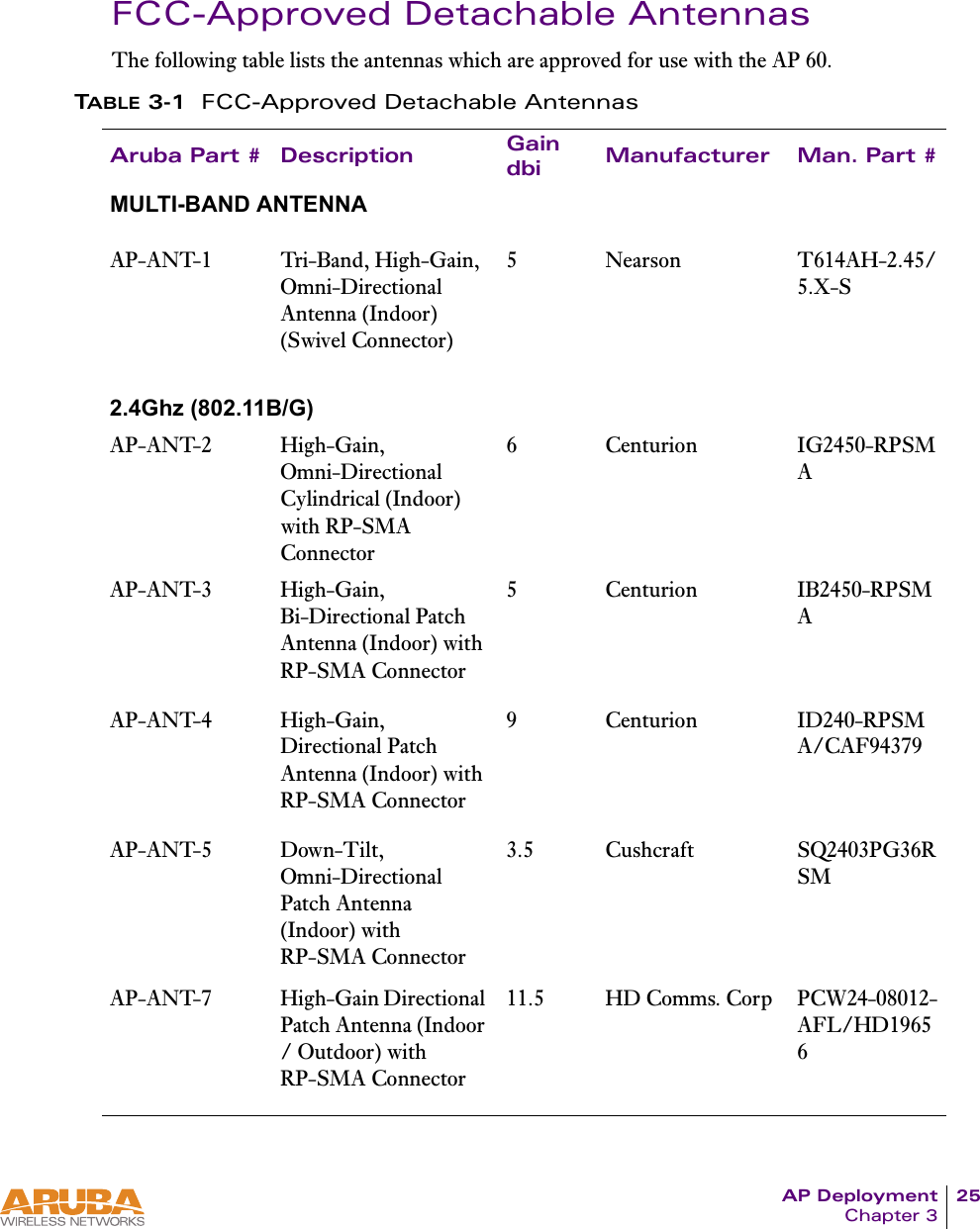
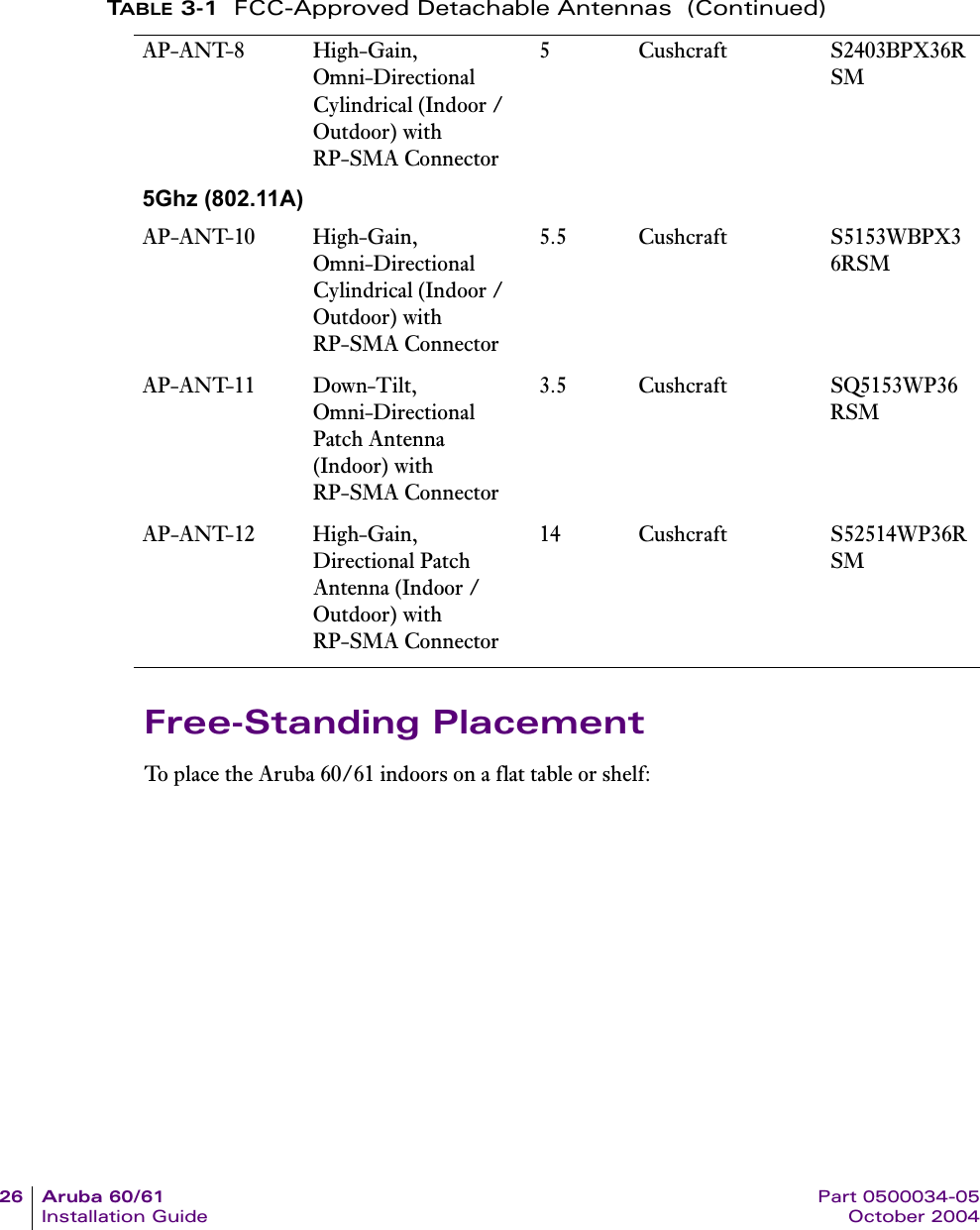
User Manual Part 1
2.
USer Manual Part 2
3.
User Manual Part 2
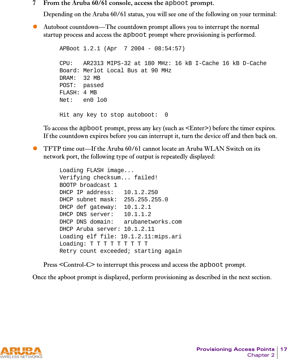
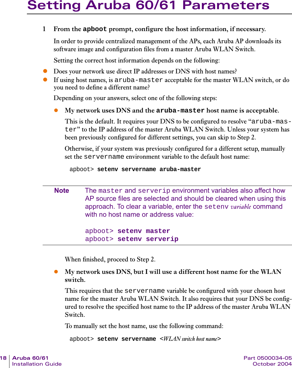
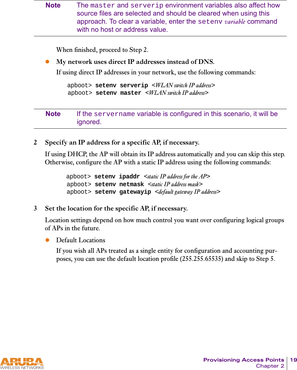
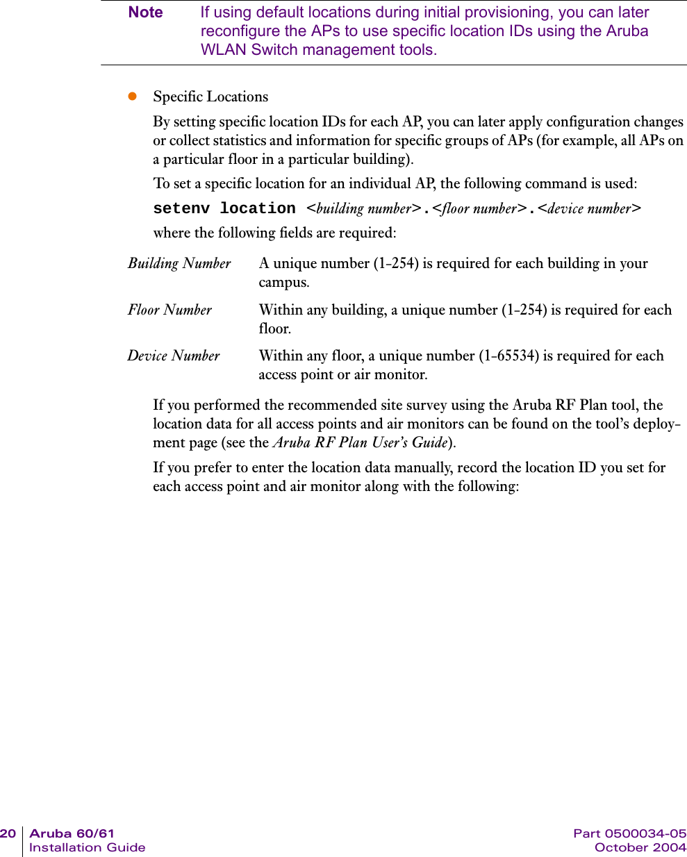
User Manual Part 1
Navigation menu
Upload a User Manual
Namespaces
Wiki Guide
HTML
PDF
Info
Views
User Manual
Discussion / Help
Navigation