Hewlett Packard Enterprise ARUBA70 802.11 .a/.b/.g Access Point User Manual
Aruba Networks, Inc. 802.11 .a/.b/.g Access Point
UserManual.wiki
>
Hewlett Packard Enterprise
>
ARUBA70 User Manual
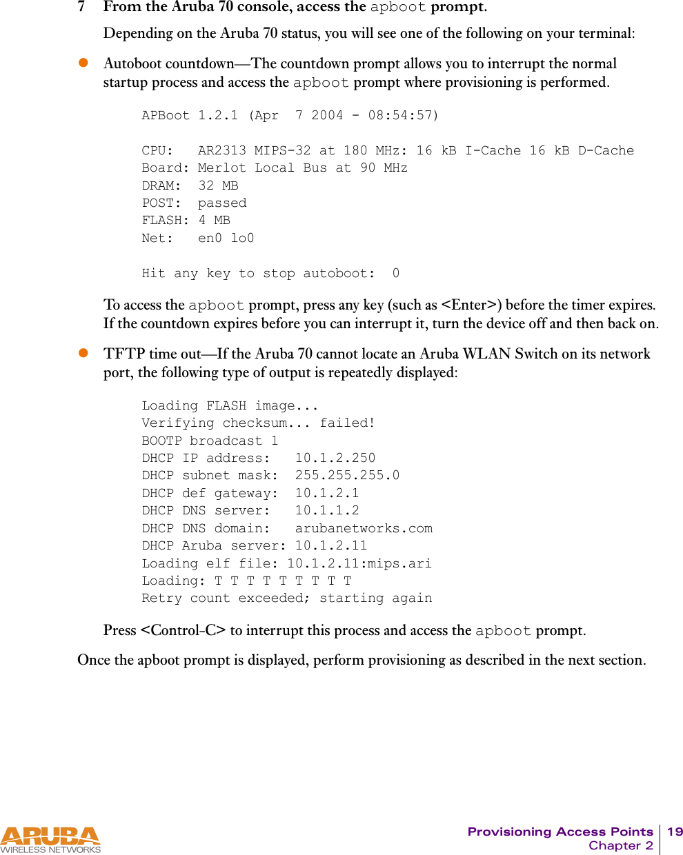
>
User Manual
Contents
1.
User Manual
2.
Users Manual
User Manual
Navigation menu
Upload a User Manual
Namespaces
Wiki Guide
HTML
PDF
Info
Views
User Manual
Discussion / Help
Navigation
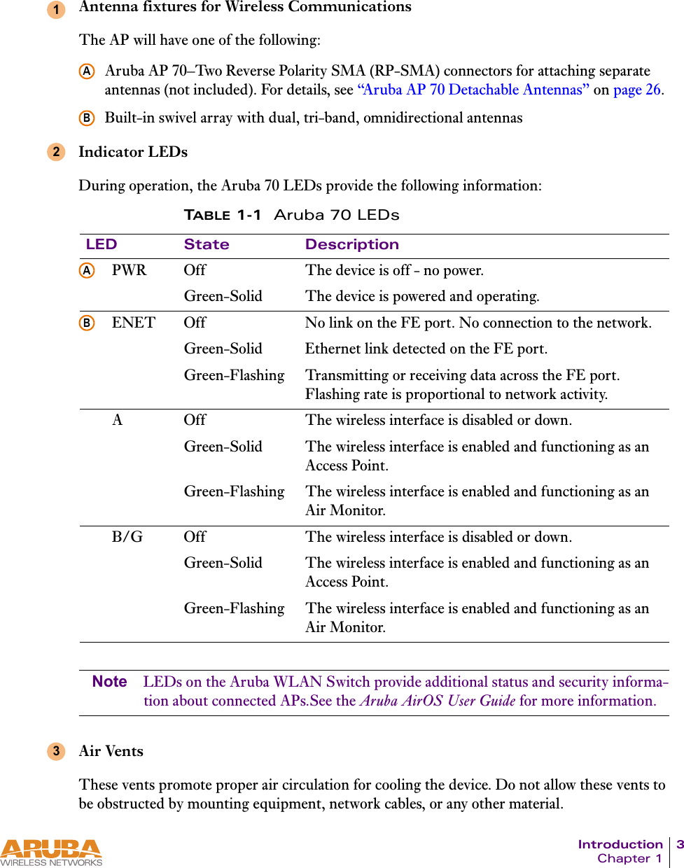
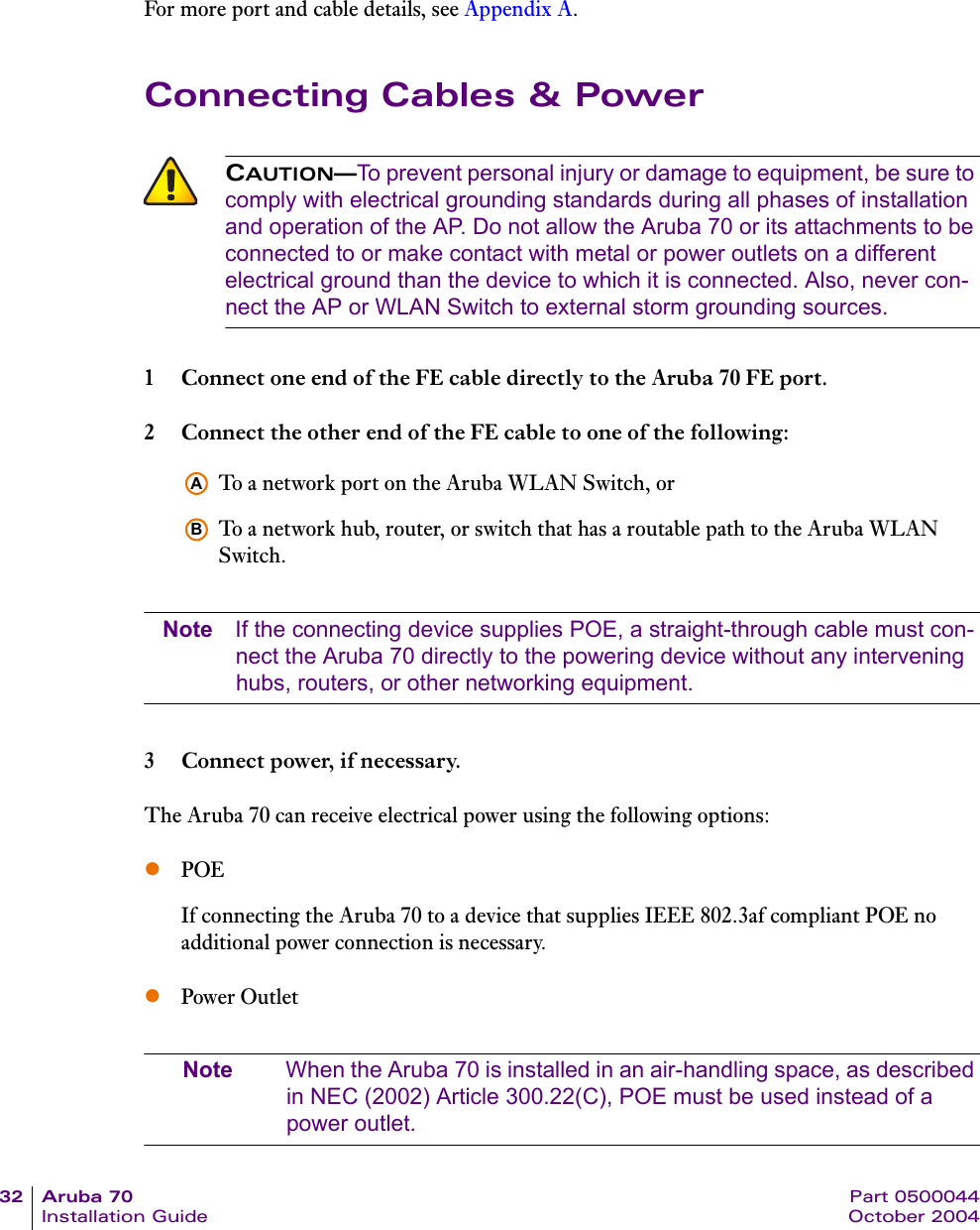
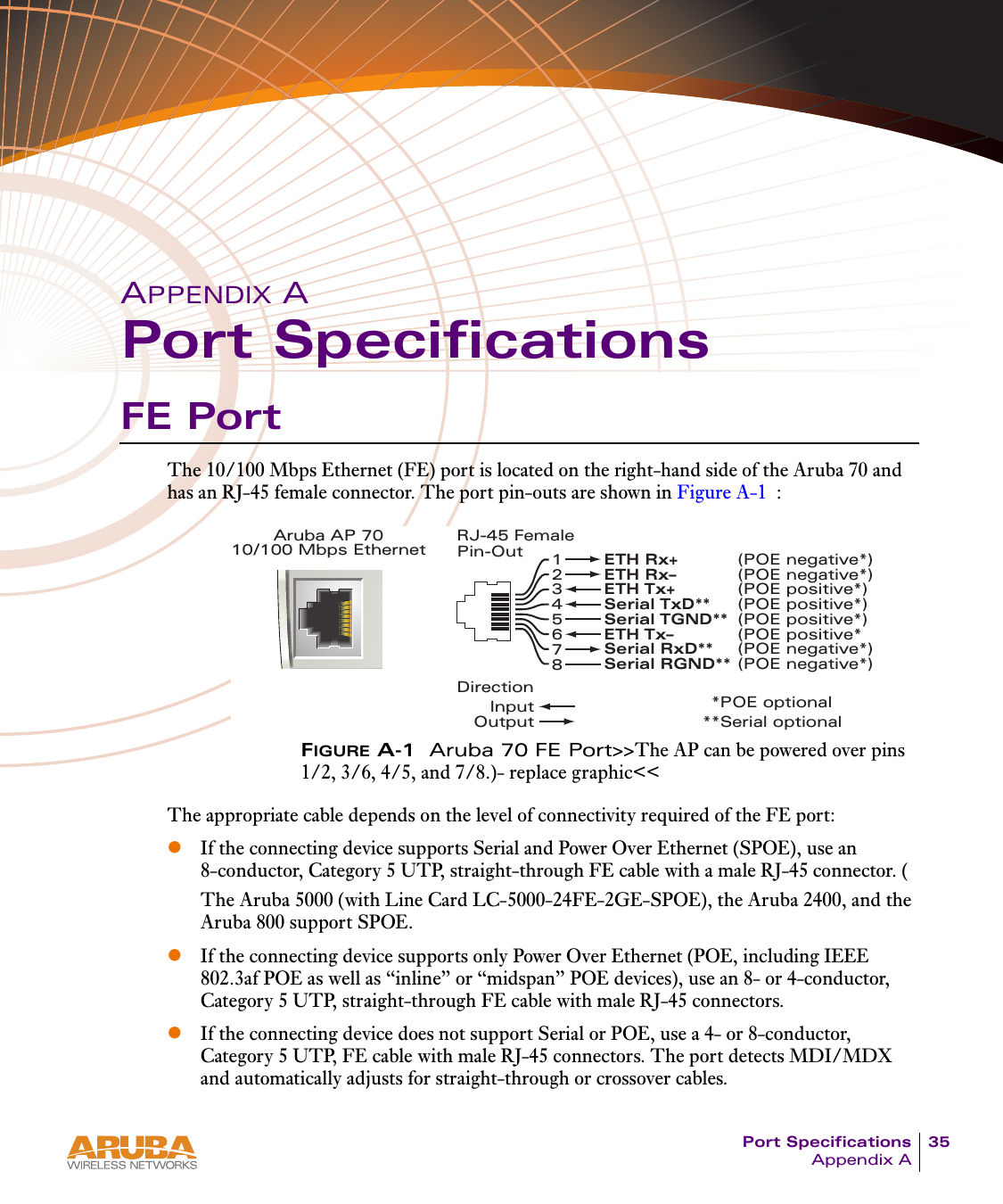
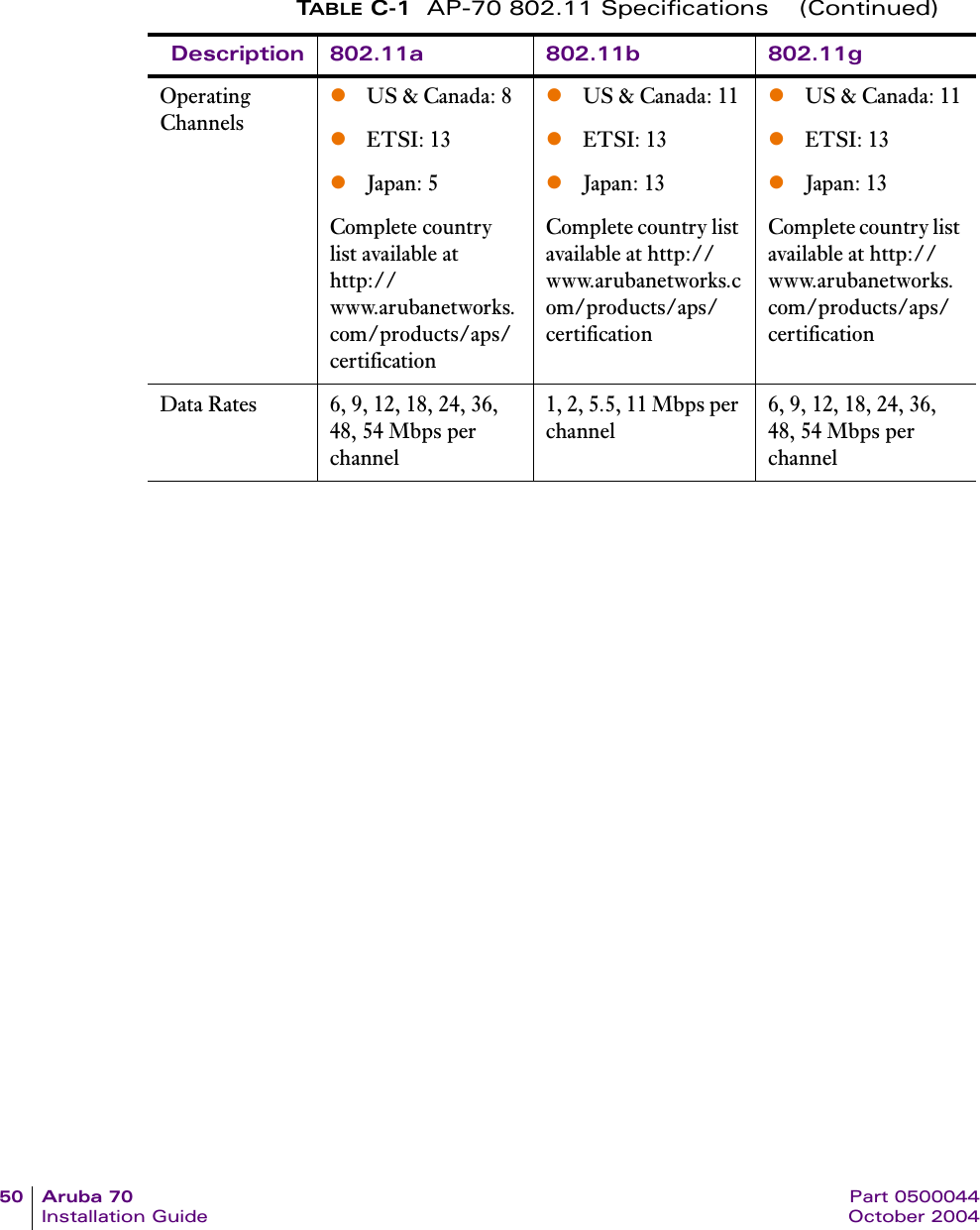
![40 Aruba 70 Part 0500044Installation Guide October 20042 When prompted, log in to the Aruba WLAN Switch as the administrator:This will present you with the Aruba WLAN Switch SOE console prompt:3 Connect to the Aruba WLAN Switch port to which the Aruba 70 is physically attached:where slot number is the physical slot of the line card in the WLAN switch, and port number is the physical port.If the AP has not finished booting, allow the Autoboot timer to expire. When the device has booted, the AP support prompt (#) will appear.Direct Terminal ConnectionThis method requires that the Aruba 70 is connected to a compatible serial console using the Aruba serial breakout adapter (see “Connecting the Console Terminal” on page 17).1 Set up your local terminal.This procedure requires a terminal or computer running terminal emulation software with the following settings:2 Establish console communication.Press <Enter> a few times to establish communication between the Aruba 70 and terminal.If the AP has not finished booting, allow the Autoboot timer to expire. When the device has booted, the AP Support prompt (#) will appear.user: adminpassword: <administrator password (not displayed)>Available commands: baud [9600|19200|38400|57600|115200] connect <slot/port> exit (no args)soe>soe> connect <slot number>/<port number>Ta b l e 3 - 2 Console Terminal SettingsBaud Rate Data Bits Parity Stop Bits Flow Control9600 8 None 1 None](https://usermanual.wiki/Hewlett-Packard-Enterprise/ARUBA70.User-Manual/User-Guide-476766-Page-44.png)
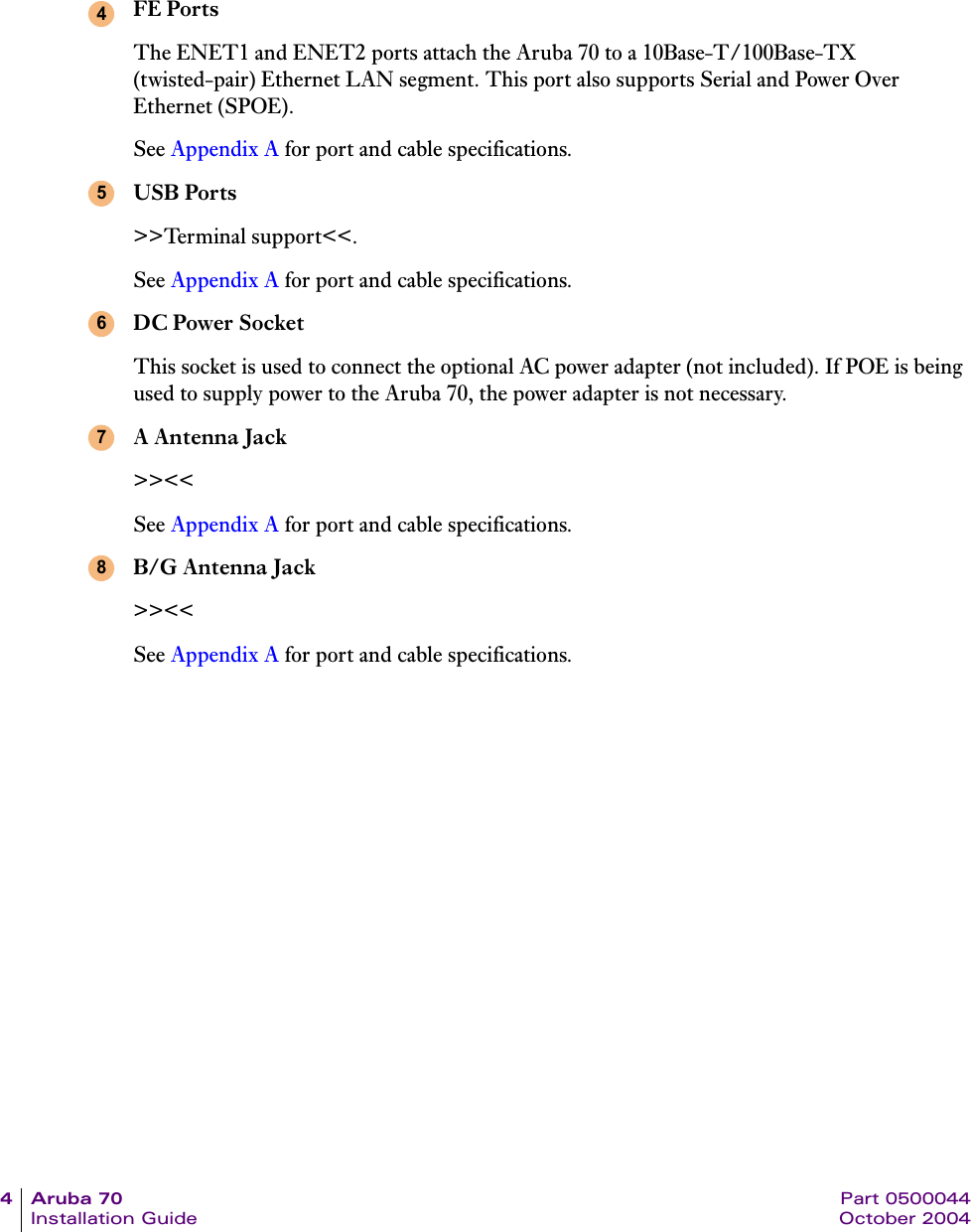
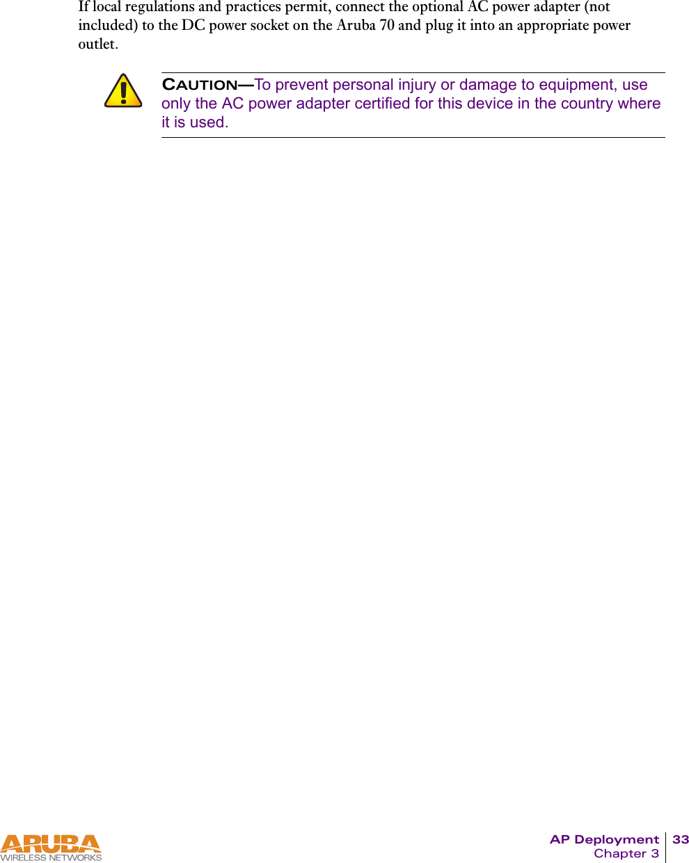
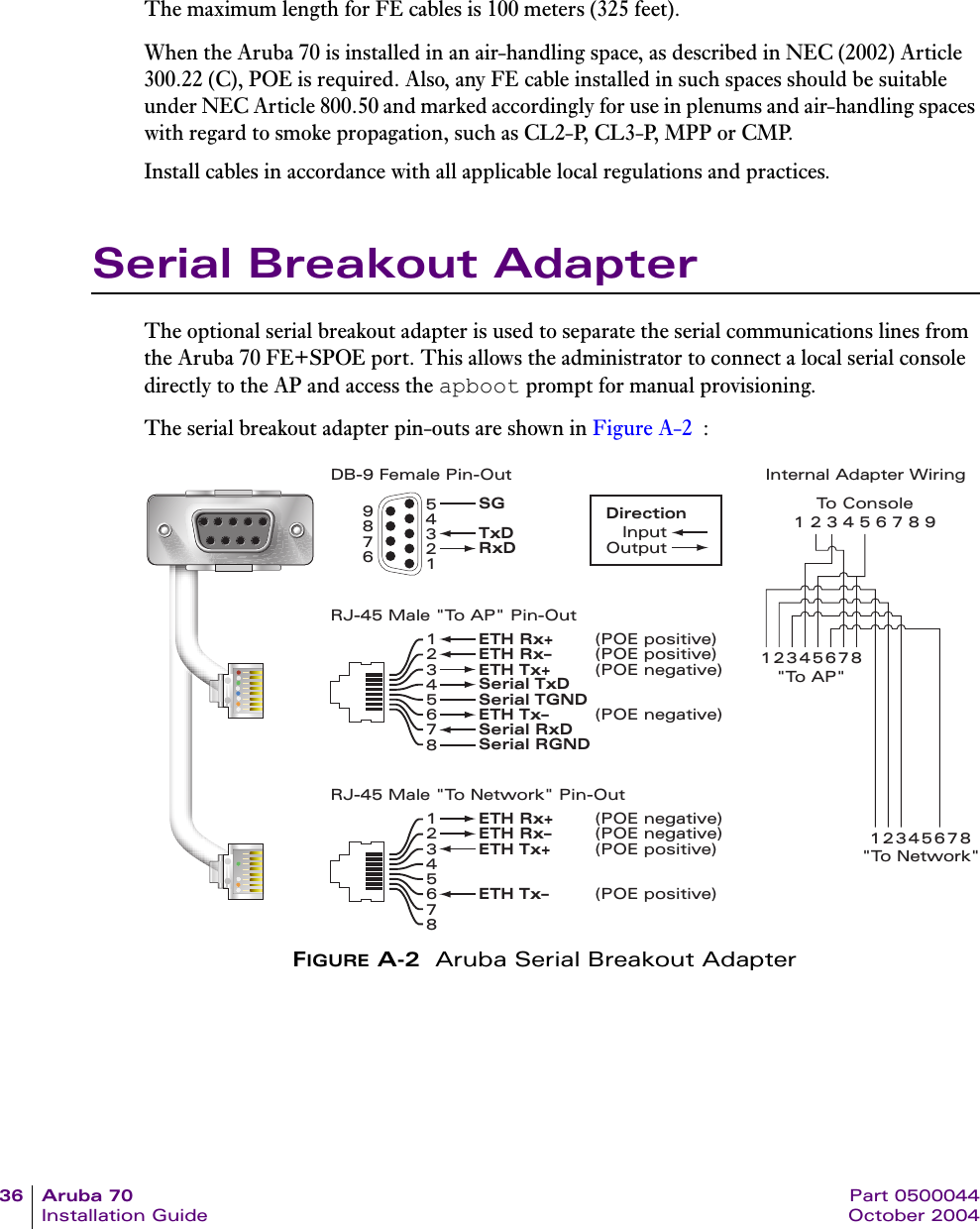
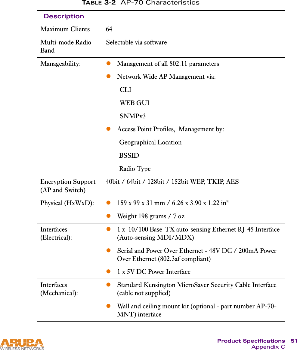
![42 Aruba 70 Part 0500044Installation Guide October 2004AP SupportAccess LevelszUser AccessUser access is a low security level, featuring only the most basic commands. It is available without any additional login after the AP has booted.zPrivileged AccessPrivileged-level access requires the privileged password (the same privileged password used on the switch) to be entered using the user level enable command. The privileged access level is available only after the AP has successfully booted and synchronized with WLAN switch.User Commandszping <host|IP address>Verify IP connectivity between the AP and the host address.zrouteDisplay the contents of the AP route table.zifconfigDisplay the AP’s IP address settings.zenable <privileged password>Access the AP Support privileged mode.Privileged CommandsIn addition to the user commands, the following commands are available upon successfully entering the privileged mode:zpszshow [config|stats|version]Note These commands should be used only as directed by Aruba Customer Support.](https://usermanual.wiki/Hewlett-Packard-Enterprise/ARUBA70.User-Manual/User-Guide-476766-Page-46.png)

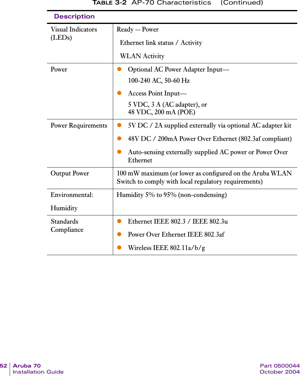
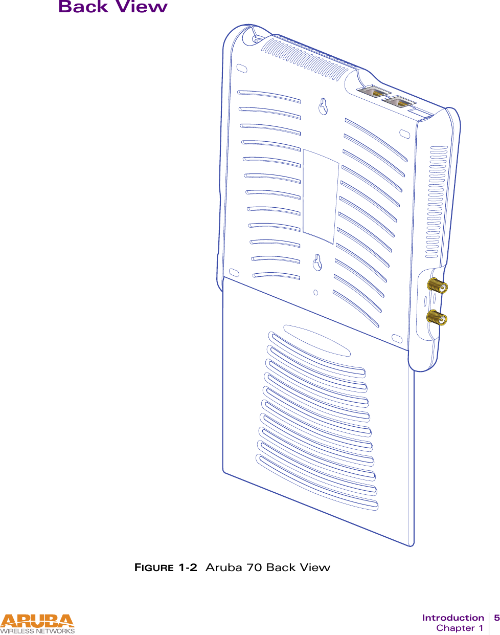
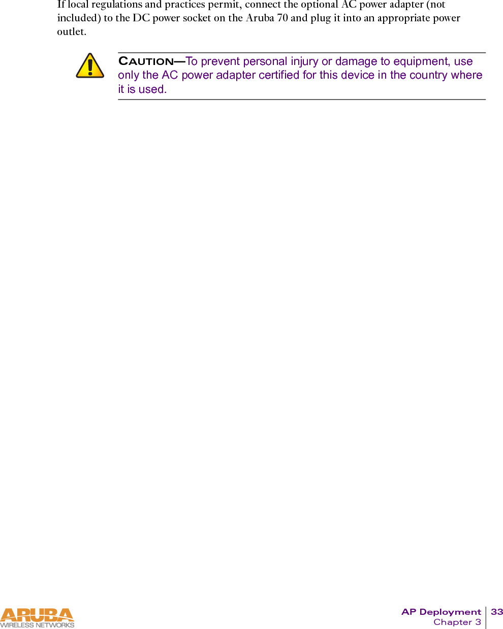
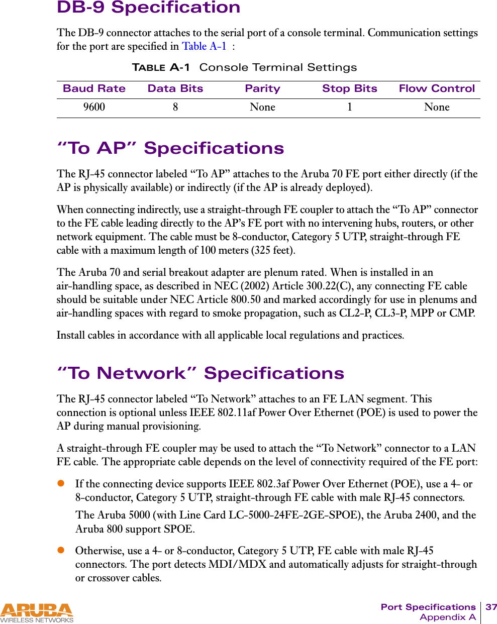
![Product Specifications 55Appendix CText ConventionsThe following conventions are used throughout this manual to emphasize important concepts:TABLE 3-3 Text ConventionsType Style DescriptionItalics This style is used to emphasize important terms and to mark the titles of books.System items This fixed-width font depicts the following:zSample screen outputzSystem promptszFilenames, software devices, and certain commands when men-tioned in the text.Commands In the command examples, this bold font depicts text that the user must type exactly as shown.<Arguments> In the command examples, italicized text within angle brackets represents items that the user should replace with information appropriate to their specific situation. For example:# send <text message>In this example, the user would type “send” at the system prompt exactly as shown, followed by the text of the message they wish to send. Do not type the angle brackets.[ Optional ] In the command examples, items enclosed in brackets are optional. Do not type the brackets.{ Item A | Item B } In the command examples, items within curled braces and separated by a vertical bar represent the available choices. Enter only one choice. Do not type the braces or bars.](https://usermanual.wiki/Hewlett-Packard-Enterprise/ARUBA70.User-Manual/User-Guide-476766-Page-59.png)