Hewlett Packard Enterprise DNMA83 Wireless mini PCI Card User Manual
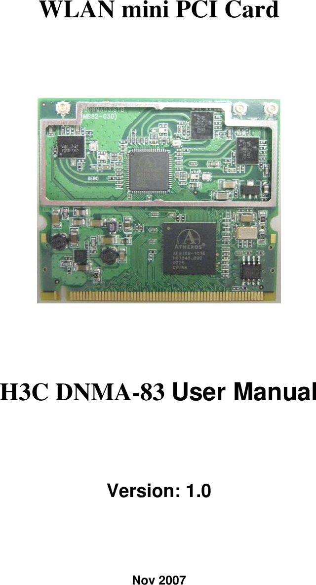
Hewlett-Packard Company Wireless mini PCI Card
UserManual.wiki
>
Hewlett Packard Enterprise
>
DNMA83 User Manual
>
User Manual
Contents
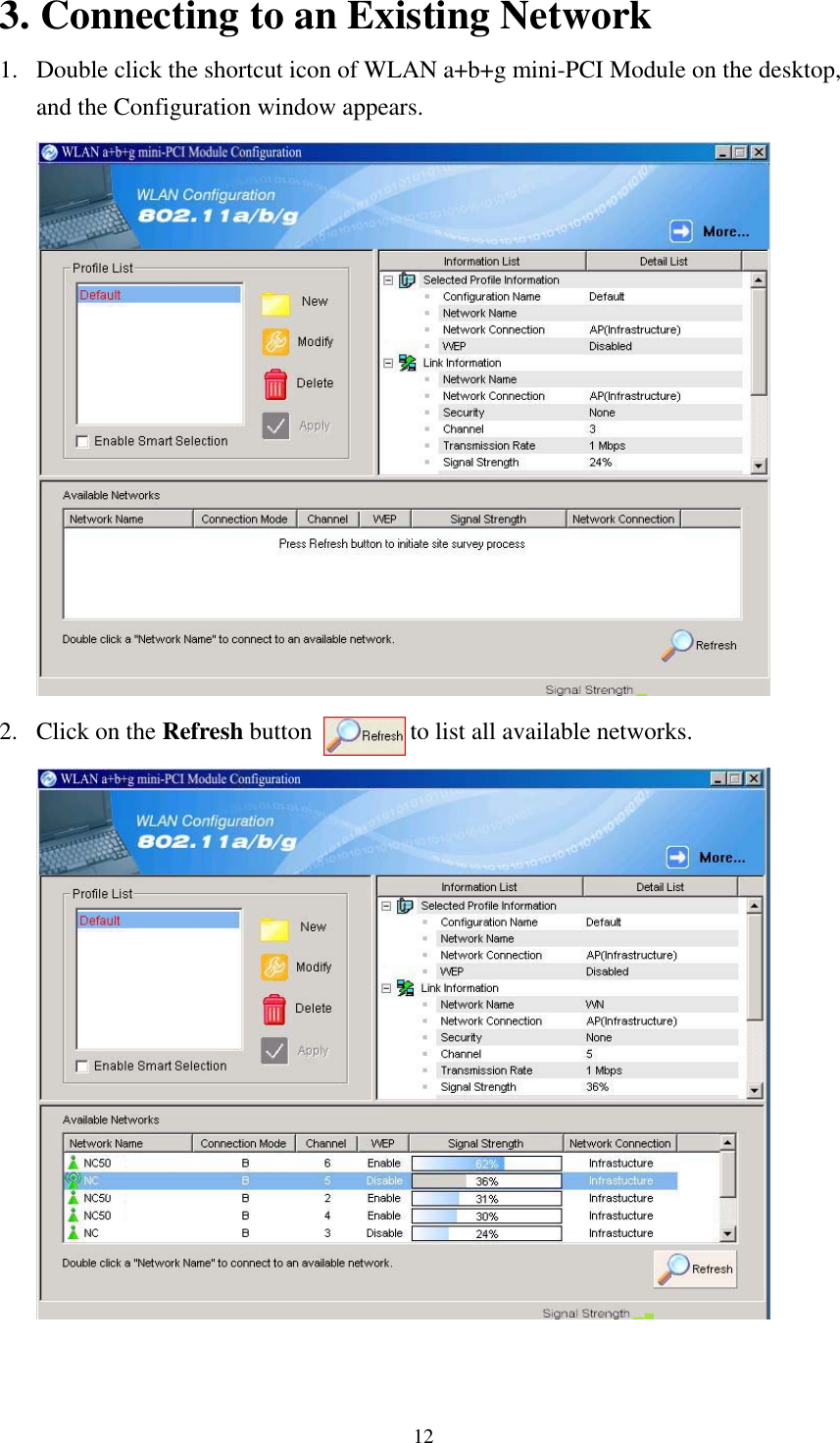
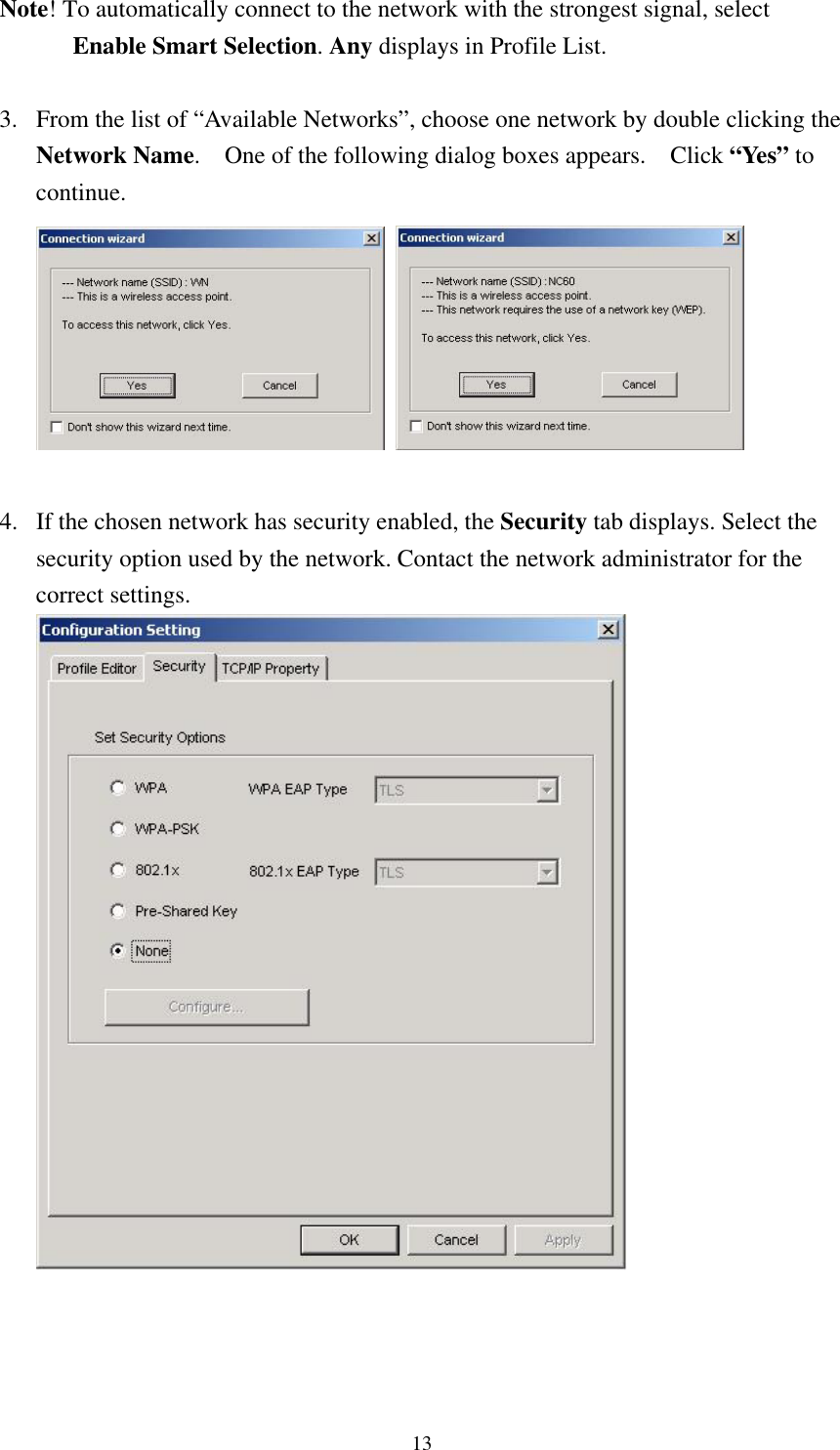
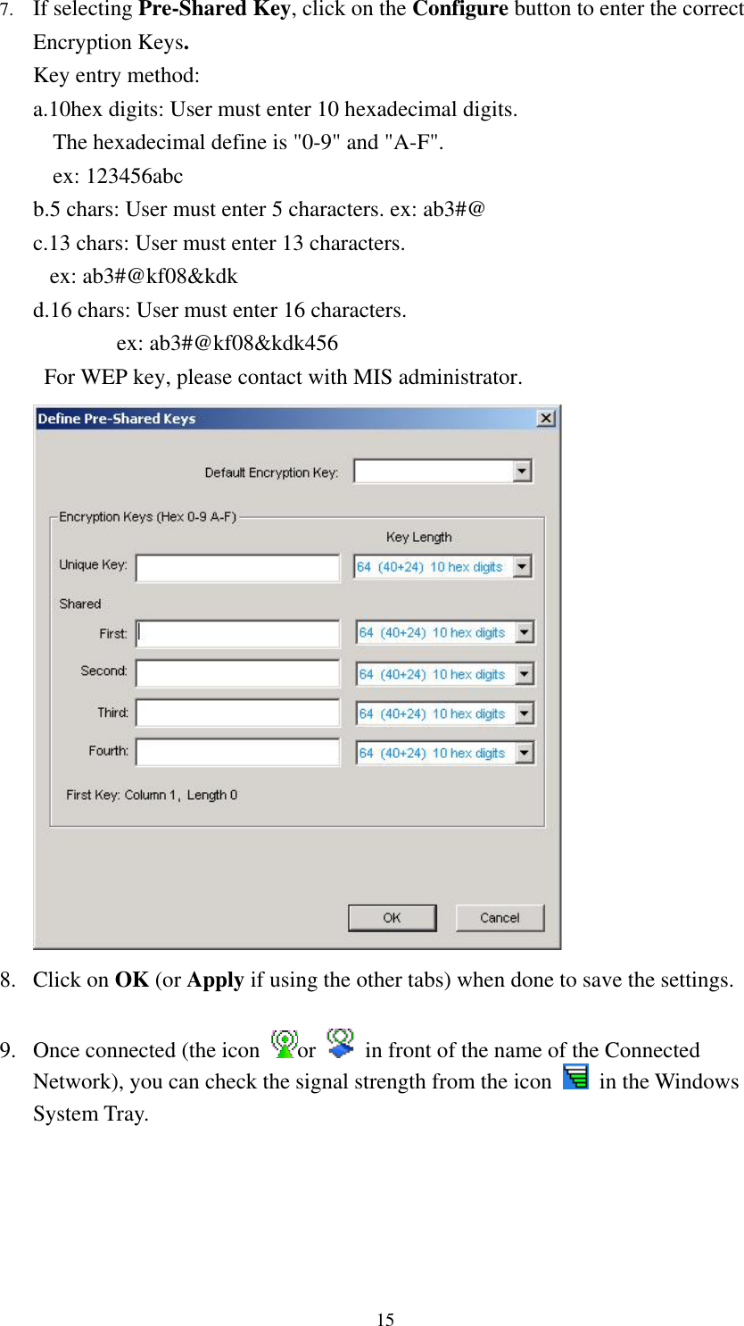
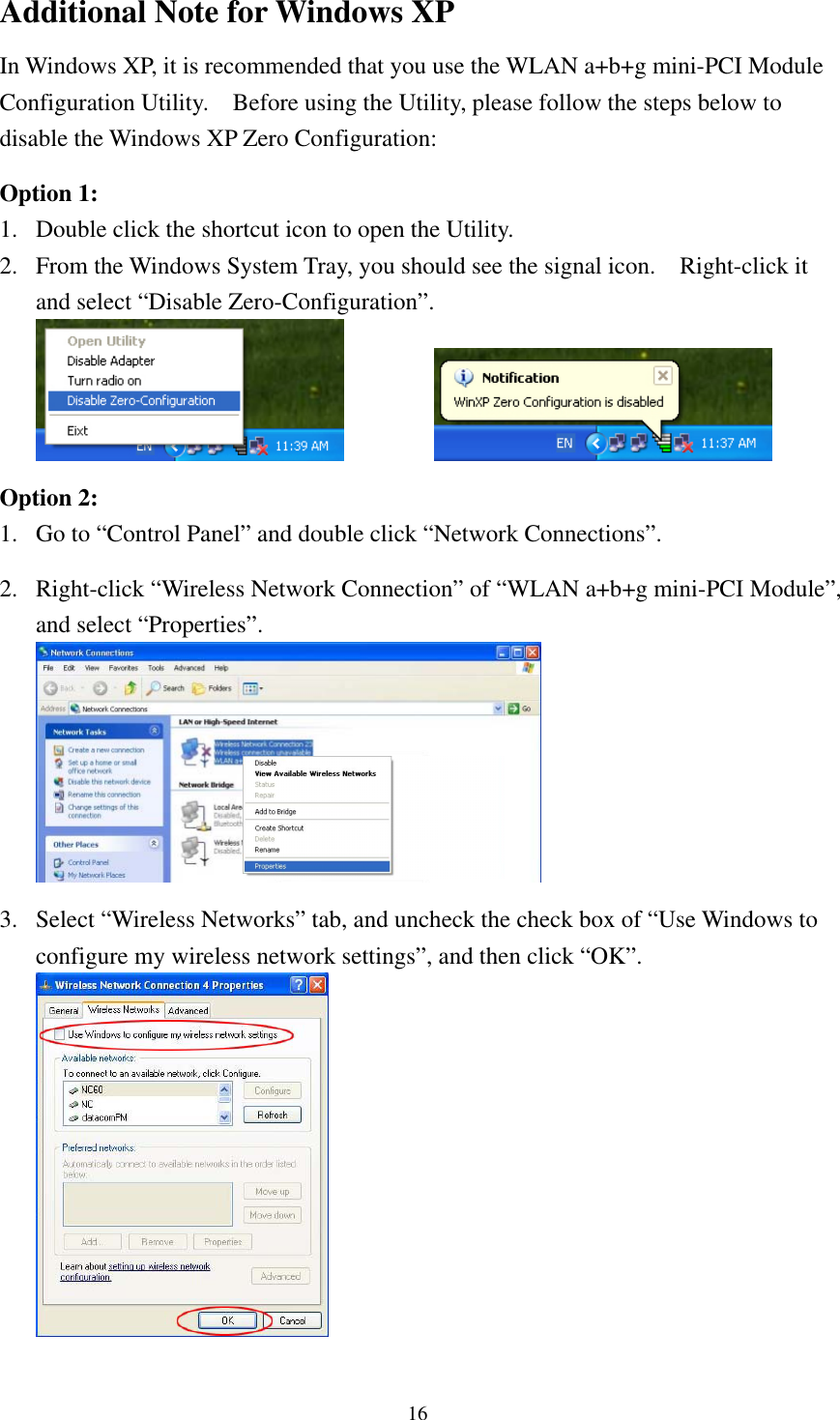
1.
User Manual
2.
Quick Start Guide
User Manual
Navigation menu
Upload a User Manual
Namespaces
Wiki Guide
HTML
PDF
Info
Views
User Manual
Discussion / Help
Navigation