Hewlett Packard Enterprise MRLBB0801 MSM317 Access Device User Manual MSM317 Access Device Installation Guide
Hewlett-Packard Co MSM317 Access Device MSM317 Access Device Installation Guide
user manual
MSM317 Access Device Installation Guide
This guide describes how to physically install the MSM317 in an electrical outlet box
and make all necessary power and network connections. This guide assumes that
before installing the MSM317, all configuration issues have been addressed as
described in the MSM317 Access Device Installation and Getting Started Guide
available at: www.procurve.com/customercare/support/manuals/index.htm.
Package contents
Professional installation required
Professional installation of the MSM317 is required for proper RF operation and compliance.
Please consult with a professional installer who is trained in RF installation and knowledgeable
about local regulations (including building and wiring codes) to ensure that the MSM317 is
operating in accordance with channel, power, indoor/outdoor restrictions and license
requirements for the intended country of operation.
Safety information
Take note of the following safety information during installation of the MSM317:
• If your network covers an area served by more than one power distribution system, be sure
all safety grounds are securely interconnected.
• Network cables may occasionally be subject to hazardous transient voltages (caused by
lightning or disturbances in the electrical power grid).
• Handle exposed metal components of the network with caution.
• This product does not have a power switch. It is powered-on when the Uplink port is plugged
into a PoE power source.
• MSM317 body
• Two faceplates (NEMA-WD6 and BS 4662)
• Two trim panels (NEMA-WD6 and BS 4662)
• Two mounting screws
•This guide
The MSM317 Access Device is a
wireless/wired end-point solution with
an integrated four-port (plus uplink)
managed Ethernet switch that can be
installed in a standard NEMA-WD6
(US) or BS 4662 (International)
electrical outlet box.
It provides a complete connectivity
solution for hospitality or multiple
dwelling unit applications, supporting
a variety of IP-based in-room
applications over a single wire.
NEMA-WD6 Version
(J9422A)
BS 4662 Version
(J9423A)
2MSM317 Access Device Installation Guide
• This product and all interconnected equipment must be installed indoors within the same
building, including all associated network connections as described by Environment A of the
IEEE 802.3af standard.
• It is normal for the rear metal cover of the MSM317 to get hot during operation. The cover is a
heat sink and is used to dissipate the heat generated by the MSM317.
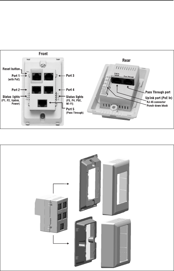
MSM317 connectors and status lights
MSM317 components
Faceplate Trim Panel
MSM317 Body
NEMA-WD6 Version
BS 4662 Version
MSM317 Access Device Installation Guide 3
Installation procedure
A. Attach the faceplate
Place the appropriate faceplate (NEMA-WD6 for US or BS 4662 for international) over the
front of the MSM317 body and press firmly to snap it into place.
B. Prepare the electrical outlet box
The MSM317 requires a single-gang electrical outlet box mounted in a wall cavity. The US version
requires a box conforming to NEMA-WD6, with a minimum depth of 1.4 inches. The International
version requires a box conforming to BS 4662, with a minimum depth of 35mm.
1. Install an appropriate electrical outlet box. Or if using an existing electrical outlet box,
disconnect and remove any existing equipment.
2. Run the required cables through the bottom of the electrical outlet box allowing sufficient
slack for the cables to reach the not-yet installed MSM317.
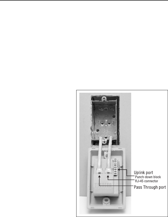
C. Connect the cables
1. Connect an Ethernet cable to the
Uplink port either via the RJ-45
connector or the Punch-down
block. Do not connect to both.
(See Punch-down block wiring on
page 4 for wiring details.)
2. If required, connect the cable
providing support for pass-through
devices to the Pass Through port.
D. Mount the MSM317
1. Attach the MSM317 to the
electrical outlet box using the
supplied mounting screws.
2. Place the appropriate trim panel
(US or International) over the front
of the MSM317 body and press
firmly to snap it into place.
E. Configure the MSM317
For details, see the MSM317 Access
Device Installation and Getting
Started Guide.
© Copyright 2009 Hewlett-Packard Development Company, L.P.
The information contained herein is subject to change without notice.
Printed in
5992-5496
*5992-5496*
4MSM317 Access Device Installation Guide
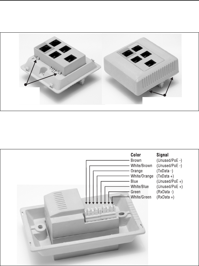
Faceplate and trim panel removal
To remove the faceplate, slightly push in two tabs on one side of the MSM317 body with a small
screwdriver. To remove the trim panel, pry off the trim panel with a small flat screwdriver.
Punch-down block wiring
When terminating a cable run with the Punch-down block, always use solid conductor cables.
Stranded cables may not make good connections. To ensure good connections, install cables
into the individual Punch-down connectors using a 110-style tool.
CAUTION: Do not connect both the Punch-down block and the Uplink port to a network. Only
one connection can be used at a time.
Press here
to remove
the faceplate. Use a screwdriver to
pry off trim panel here.
(BS 4662 version shown.)
Federal Communication Commission Interference Statement
This equipment has been tested and found to comply with the limits for a Class B digital device, pursuant to Part
15 of the FCC Rules. These limits are designed to provide reasonable protection against harmful interference in
a residential installation. This equipment generates, uses and can radiate radio frequency energy and, if not
installed and used in accordance with the instructions, may cause harmful interference to radio communications.
However, there is no guarantee that interference will not occur in a particular installation. If this equipment does
cause harmful interference to radio or television reception, which can be determined by turning the equipment off
and on, the user is encouraged to try to correct the interference by one of the following measures:
z Reorient or relocate the receiving antenna.
z Increase the separation between the equipment and receiver.
z Connect the equipment into an outlet on a circuit different from that to which the receiver is connected.
z Consult the dealer or an experienced radio/TV technician for help.
Any changes or modifications not expressly approved by the party responsible for compliance could void the
user's authority to operate this equipment.
This device complies with Part 15 of the FCC Rules.
Operation is subject to the following two conditions: (1) This device may not cause harmful interference, and (2)
this device must accept any interference received, including interference that may cause undesired operation.
This device and its antenna(s) must not be co-located or operating in conjunction with any other antenna or
transmitter.
Country Code selection feature to be disabled for products marketed to the US/CANADA
Radiation Exposure Statement:
This equipment complies with FCC / IC RSS-102 radiation exposure limits set forth for an uncontrolled
environment. This equipment should be installed and operated with minimum distance 20cm between the
radiator & your body.
This Class [B] digital apparatus complies with Canadian ICES-003.
Cet appareil numérique de la classe [B] est conforme à la norme NMB-003 du Canada.
The Zurich product shall provide an 802.11b/g radio configured as an AP.