Hewlett Packard Enterprise MRLBB1003 WLAN 802.11a/b/g/n mini PCIe module User Manual E MSM466 R Access Point Install Guide

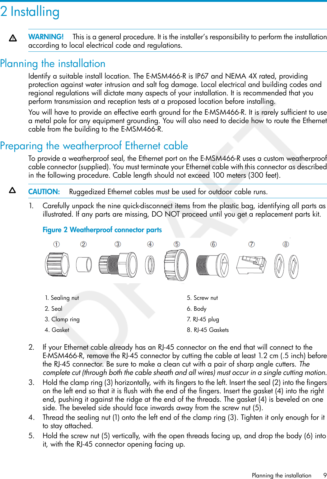
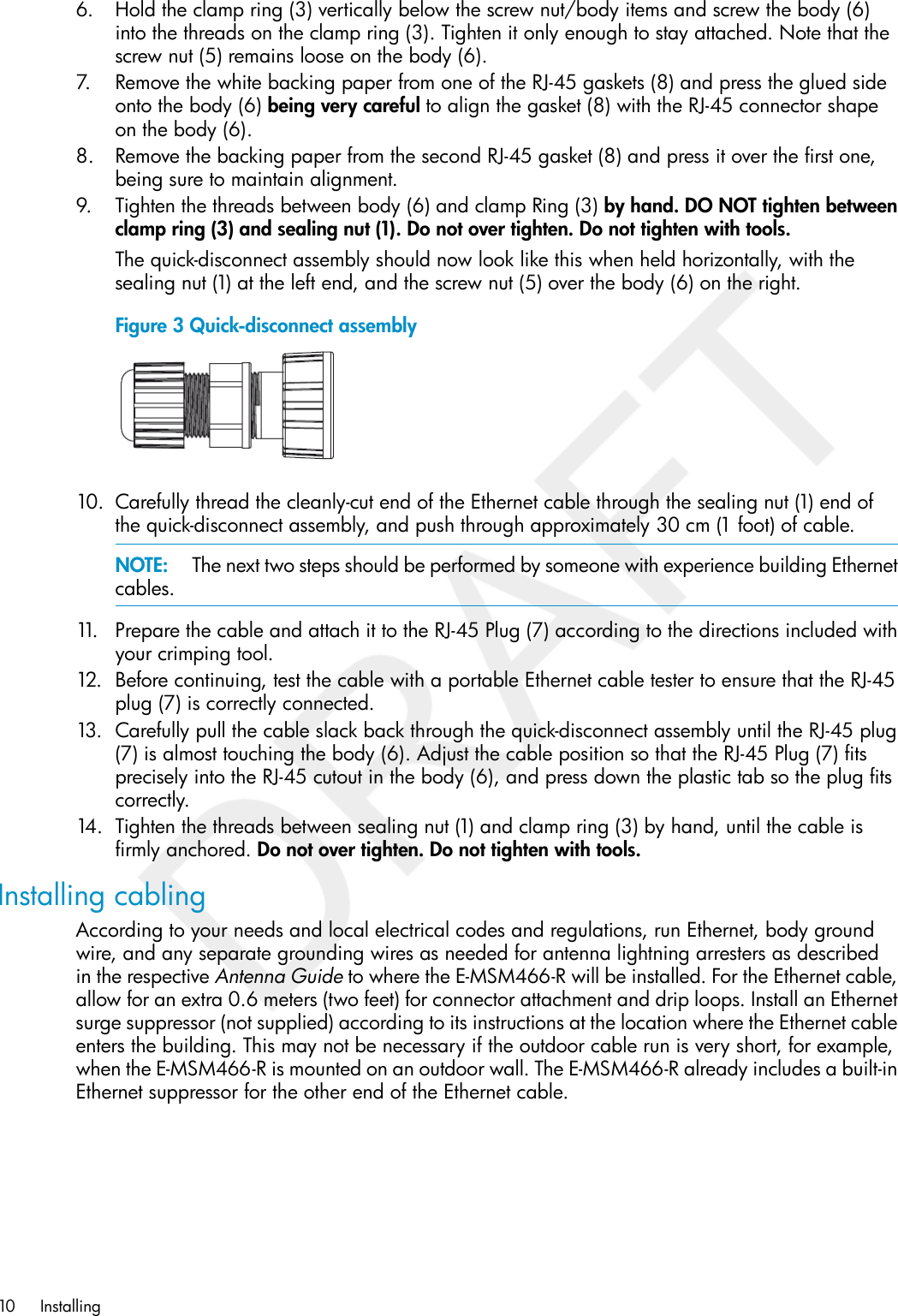
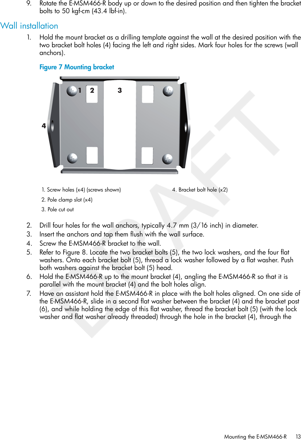
Hewlett-Packard Co WLAN 802.11a/b/g/n mini PCIe module E MSM466 R Access Point Install Guide

Contents

Updated User Manual

HPE-MSM466-R Access Point Install GuideAbstractThis document describes how to install and initially configure the E-MSM466-R ruggedized Access Point. Professional wirelessand electrical equipment experience is required.**5998–1426**HP Part Number: 5998-1426Published: July 2011Edition: Draft
© Copyright 2011 Hewlett-Packard Development Company, L.P.The information contained herein is subject to change without notice. The only warranties for HP products and services are set forth in the expresswarranty statements accompanying such products and services. Nothing herein should be construed as constituting an additional warranty. HP shallnot be liable for technical or editorial errors or omissions contained herein.AcknowledgmentsMicrosoft®, Windows®, Windows® XP, and Windows NT® are U.S. registered trademarks of Microsoft Corporation.Adobe® and Acrobat® are trademarks of Adobe Systems Incorporated.WarrantyWARRANTY STATEMENT: To obtain a copy of the warranty for this product, see the warranty information website:www.hp.com/go/storagewarrantyRevision HistorydateRevision #description of revision
Contents1 Preparing for Installation..............................................................................5Package Contents.....................................................................................................................5Identifying E-MSM466-R components..........................................................................................5Protection Equipment Needed....................................................................................................5Ports.......................................................................................................................................6Radios and antennas................................................................................................................6Reset button.............................................................................................................................6Important information to read before installing..............................................................................6Powering the E-MSM466-R.........................................................................................................7About controlled mode and autonomous mode.............................................................................7Status LED behavior in controlled mode...................................................................................7Status LED behavior in autonomous mode...............................................................................82 Installing...................................................................................................9Planning the installation.............................................................................................................9Preparing the weatherproof Ethernet cable...................................................................................9Installing cabling....................................................................................................................10Mounting the E-MSM466-R......................................................................................................11Pole installation.................................................................................................................11Wall installation................................................................................................................13Connecting the E-MSM466-R...................................................................................................15Attaching the grounding wire and antennas..........................................................................15Attaching the Ethernet cable................................................................................................15Powering on the E-MSM466-R..................................................................................................163 Initially Configuring (Autonomous mode).....................................................17Configuring your computer......................................................................................................17Connecting the cables and powering on the E-MSM466-R...........................................................17Switching the E-MSM466-R to autonomous mode........................................................................17Logging in.............................................................................................................................17Configuring basic wireless protection........................................................................................18Assigning an IP address to the E-MSM466-R..............................................................................18Testing the wireless network.....................................................................................................19Before performing additional configuration................................................................................194 Working with antennas.............................................................................20E-MSM466-R available antennas..............................................................................................205 Support and other resources......................................................................21Online Documentation.............................................................................................................21Contacting HP........................................................................................................................21HP Websites..........................................................................................................................21Typographic conventions.........................................................................................................21A Regulatory information..............................................................................23Notice for U.S.A.....................................................................................................................23Manufacturer's FCC Declaration of Conformity Statement........................................................23FCC Class B statement........................................................................................................23Notice to Professional Installers............................................................................................23Notice for Canada.................................................................................................................24Notice for the European Community..........................................................................................24Countries of Operation & Conditions of Use..........................................................................242.4 GHz Operation.......................................................................................................255 GHz Operation.........................................................................................................25Contents 3
Operation Using 5 GHz Channels in the European Community...........................................25Supported External Antennas...................................................................................................25Notice for Brazil, Aviso aos usuários no Brasil............................................................................25Notice for Taiwan...................................................................................................................26DGT LPD (Low Power Device) Statement.................................................................................26Korean notices.......................................................................................................................26Class B equipment.............................................................................................................26Turkish recycling notice............................................................................................................26Vietnamese Information Technology and Communications compliance marking...............................26DOC for the European Community............................................................................................27Disposal of Waste Equipment by Users in Private Household in the European Union...................28English recycling notice......................................................................................................28Bulgarian recycling notice...................................................................................................28Czech recycling notice........................................................................................................28Danish recycling notice.......................................................................................................28Dutch recycling notice.........................................................................................................28Estonian recycling notice.....................................................................................................29Finnish recycling notice.......................................................................................................29French recycling notice.......................................................................................................29German recycling notice.....................................................................................................29Greek recycling notice........................................................................................................29Hungarian recycling notice.................................................................................................29Italian recycling notice........................................................................................................30Latvian recycling notice.......................................................................................................30Lithuanian recycling notice..................................................................................................30Polish recycling notice.........................................................................................................30Portuguese recycling notice.................................................................................................30Romanian recycling notice..................................................................................................31Slovak recycling notice.......................................................................................................31Spanish recycling notice.....................................................................................................31Swedish recycling notice.....................................................................................................314 Contents
1 Preparing for InstallationThis chapter shows you how to get started using the E-MSM466-R Access Point.Package Contents•One E-MSM466-R•One weatherproof RJ-45 Ethernet connector•One pole mount/wall mount bracket•Bracket bolts (x2), lock washers (x2), flat washers (x4)•Wall anchors (x4) and screws (x4)•Pole clamps (x2) for a 5 cm (2 inch) diameter pole•DocumentationIdentifying E-MSM466-R componentsE-MSM466-R key components are identified as follows:Figure 1 E-MSM466-R key components1 2653 41 14. Ethernet connector1. Radio 2 antenna connectors (x3)5. Reset button2. Vent Nut (do not remove)6. Status LEDs (Power, Ethernet, Radio 1, Radio 2)3. Grounding lug with screwNOTE: Three Radio 1 antenna connectors are available on the opposite end of the E-MSM466-R.Protection Equipment NeededIn addition to the items supplied with the E-MSM466-R, protection equipment will be requiredaccording to your electrical code. Consult the respective Antenna Guide (available online, searchby antenna part number), including the Lightning Arrester section for important safety informationand instructions. Note that although the E-MSM466-R includes a built-in Ethernet surge suppressor,you should add an Ethernet surge suppressor where the Ethernet cable enters the building.Package Contents 5
PortsEthernet port: Auto-sensing 10/100/1000 BaseT Ethernet port with RJ-45 connector. The portsupports Power over Ethernet (PoE) 802.3af and 802.3at.Radios and antennasThe E-MSM466-R includes no integrated antennas. It provides three antenna connectors for eachradio, color-coded red, green, and blue. When connecting the antenna cables, be sure to respectthe color-coding. See “E-MSM466-R available antennas” (page 20).Reset buttonThe Reset button is on the bottom of the E-MSM466-R, labeled as 5 in “E-MSM466-R keycomponents” (page 5). To reset (same as power cycling) the E-MSM466-R, press then releasethe Reset button. To reset the E-MSM466-R to factory defaults, press and hold the Reset button untilthe status LEDS flash three times, then release.Important information to read before installingWARNING! PROFESSIONAL INSTALLATION REQUIRED.For outdoor or indoor installation. Prior to installing or using the E-MSM466-R, consult with aprofessional installer trained in RF installation and knowledgeable in local regulations includingbuilding and wiring codes, safety, channel, power, outdoor/indoor restrictions, and licenserequirements for the intended country. It is the responsibility of the end user to ensure that installationand use complies with local safety and radio regulations.Surge protection and grounding: When connecting antennas installed outdoors to the E-MSM466-R,make sure that proper lightning surge protection and grounding precautions are taken accordingto local electrical code. Failure to do so may result in personal injury, fire, equipment damage, ora voided warranty. The HP hardware warranty provides no protection against damage causedby static discharge or a lightning strike. Lightening Arresters (not supplied) are available from HP(J8996A). One arrester is required for each antenna connector (6).Cabling: You must use the appropriate cables, and where applicable, surge protection, for yourgiven region. Cat 5e (or better) cabling is required.Country of use: In some regions, you are prompted to select the country of use during setup. Afterthe country has been set, the E-MSM466-R will automatically limit the available wireless channels,ensuring compliant operation in the selected country. Entering the incorrect country may result inillegal operation and may cause harmful interference to other systems.Safety: Take note of the following during installation:•If your network covers an area served by more than one power distribution system, make sureall safety grounds are securely interconnected.•Network cables are subject to hazardous transient voltages (caused by lightning or disturbancesin the electrical power grid).•Handle exposed metal components of the network with caution.•The E-MSM466-R is powered-on when connected to a PoE power source.6 Preparing for Installation
Powering the E-MSM466-RThe E-MSM466-R can be powered by:•A 10/100 or 10/100/1000 PoE-enabled switch. Various PoE-enabled switches are availablefrom HP.•HP 1-Port 802.3at Gig PoE Power Injector (JD054A).•HP 1-Port 802.3af Gig PoE Power Injector (J9407B).CAUTION: If the E-MSM466-R will be powered by a user-supplied PoE power injector, use onlya gigabit-compatible power injector. Although 10/100 PoE-enabled switches are compatible, PoEinjectors designed for 10/100 networks only are NOT compatible with the E-MSM466-R.About controlled mode and autonomous modeThe E-MSM466-R can operate in one of two modes: controlled (the default) or autonomous.Switching modes resets all configuration settings to factory defaults.•Controlled mode: To become operational, the E-MSM466-R must establish a managementtunnel with an E-MSM7xx Controller running at least v5.7.x software. The controller managesthe E-MSM466-R and provides all configuration settings. Discovery of the controller is automaticif default settings are used on the E-MSM466-R and the controller, and both devices are onthe same subnet. See Working with controlled APs in the E-MSM7xx Controllers Managementand Configuration Guide.•Autonomous mode: After being switched to autonomous mode, the E-MSM466-R operates asa stand-alone E-MSM466-R. You configure and manage an autonomous E-MSM466-R byusing its Web-based management tool, as described in “Initially Configuring (Autonomousmode)” (page 17).Status LED behavior in controlled modeTable 1 Status LED behavior in controlled modeDescriptionStatus LED behaviorThe E-MSM466-R is starting up.Power LED blinks every two seconds.The E-MSM466-R is looking for an IP address, or building the list ofVLANs on which to perform discovery. The management tool is availableuntil discovery occurs.Power LED blinks once per second.The E-MSM466-R has obtained an IP address and is attempting todiscover a controller.Power, Ethernet, and Radio LEDs blink insequence from left to right.The E-MSM466-R has found a controller and is attempting to establisha secure management tunnel with it.Power LED is on. Ethernet and Radio LEDsblink alternately.The E-MSM466-R has received a discovery reply from two or morecontrollers with the same priority setting. It is unable to connect witheither controller until the conflict is resolved.Power and Ethernet LEDs blink alternately andquickly. Radio LEDs are off.The E-MSM466-R is attempting to establish a local mesh link to a masternode.Power and Radio LEDs blink slowly.The E-MSM466-R is attempting to establish wired connectivity.Power and Ethernet LEDs blink slowly.After the discovery process is complete, and the E-MSM466-R has established a secure managementtunnel to a controller, the Power LED remains on and the Ethernet and Radio LEDs blink to indicatethe presence of traffic.Powering the E-MSM466-R 7
Status LED behavior in autonomous modeTable 2 Status LED behavior in autonomous modeDescriptionStatusLEDThe E-MSM466-R has no power.OffPowerThe E-MSM466-R is starting up. If the Power LED continues to blink after severalminutes, it indicates that the software failed to load. Reset or power cycle theE-MSM466-R. If this condition persists, contact HP customer support.BlinkingThe E-MSM466-R is fully operational.OnThe port is not connected or there is no activity.OffEthernetThe port is transmitting or receiving data.BlinkingThe radio is transmitting or receiving data.BlinkingRadio8 Preparing for Installation
2 InstallingWARNING! This is a general procedure. It is the installer’s responsibility to perform the installationaccording to local electrical code and regulations.Planning the installationIdentify a suitable install location. The E-MSM466-R is IP67 and NEMA 4X rated, providingprotection against water intrusion and salt fog damage. Local electrical and building codes andregional regulations will dictate many aspects of your installation. It is recommended that youperform transmission and reception tests at a proposed location before installing.You will have to provide an effective earth ground for the E-MSM466-R. It is rarely sufficient to usea metal pole for any equipment grounding. You will also need to decide how to route the Ethernetcable from the building to the E-MSM466-R.Preparing the weatherproof Ethernet cableTo provide a weatherproof seal, the Ethernet port on the E-MSM466-R uses a custom weatherproofcable connector (supplied). You must terminate your Ethernet cable with this connector as describedin the following procedure. Cable length should not exceed 100 meters (300 feet).CAUTION: Ruggedized Ethernet cables must be used for outdoor cable runs.1. Carefully unpack the nine quick-disconnect items from the plastic bag, identifying all parts asillustrated. If any parts are missing, DO NOT proceed until you get a replacement parts kit.Figure 2 Weatherproof connector parts5. Screw nut1. Sealing nut6. Body2. Seal7. RJ-45 plug3. Clamp ring8. RJ-45 Gaskets4. Gasket2. If your Ethernet cable already has an RJ-45 connector on the end that will connect to theE-MSM466-R, remove the RJ-45 connector by cutting the cable at least 1.2 cm (.5 inch) beforethe RJ-45 connector. Be sure to make a clean cut with a pair of sharp angle cutters. Thecomplete cut (through both the cable sheath and all wires) must occur in a single cutting motion.3. Hold the clamp ring (3) horizontally, with its fingers to the left. Insert the seal (2) into the fingerson the left end so that it is flush with the end of the fingers. Insert the gasket (4) into the rightend, pushing it against the ridge at the end of the threads. The gasket (4) is beveled on oneside. The beveled side should face inwards away from the screw nut (5).4. Thread the sealing nut (1) onto the left end of the clamp ring (3). Tighten it only enough for itto stay attached.5. Hold the screw nut (5) vertically, with the open threads facing up, and drop the body (6) intoit, with the RJ-45 connector opening facing up.Planning the installation 9
6. Hold the clamp ring (3) vertically below the screw nut/body items and screw the body (6)into the threads on the clamp ring (3). Tighten it only enough to stay attached. Note that thescrew nut (5) remains loose on the body (6).7. Remove the white backing paper from one of the RJ-45 gaskets (8) and press the glued sideonto the body (6) being very careful to align the gasket (8) with the RJ-45 connector shapeon the body (6).8. Remove the backing paper from the second RJ-45 gasket (8) and press it over the first one,being sure to maintain alignment.9. Tighten the threads between body (6) and clamp Ring (3) by hand. DO NOT tighten betweenclamp ring (3) and sealing nut (1). Do not over tighten. Do not tighten with tools.The quick-disconnect assembly should now look like this when held horizontally, with thesealing nut (1) at the left end, and the screw nut (5) over the body (6) on the right.Figure 3 Quick-disconnect assembly10. Carefully thread the cleanly-cut end of the Ethernet cable through the sealing nut (1) end ofthe quick-disconnect assembly, and push through approximately 30 cm (1 foot) of cable.NOTE: The next two steps should be performed by someone with experience building Ethernetcables.11. Prepare the cable and attach it to the RJ-45 Plug (7) according to the directions included withyour crimping tool.12. Before continuing, test the cable with a portable Ethernet cable tester to ensure that the RJ-45plug (7) is correctly connected.13. Carefully pull the cable slack back through the quick-disconnect assembly until the RJ-45 plug(7) is almost touching the body (6). Adjust the cable position so that the RJ-45 Plug (7) fitsprecisely into the RJ-45 cutout in the body (6), and press down the plastic tab so the plug fitscorrectly.14. Tighten the threads between sealing nut (1) and clamp ring (3) by hand, until the cable isfirmly anchored. Do not over tighten. Do not tighten with tools.Installing cablingAccording to your needs and local electrical codes and regulations, run Ethernet, body groundwire, and any separate grounding wires as needed for antenna lightning arresters as describedin the respective Antenna Guide to where the E-MSM466-R will be installed. For the Ethernet cable,allow for an extra 0.6 meters (two feet) for connector attachment and drip loops. Install an Ethernetsurge suppressor (not supplied) according to its instructions at the location where the Ethernet cableenters the building. This may not be necessary if the outdoor cable run is very short, for example,when the E-MSM466-R is mounted on an outdoor wall. The E-MSM466-R already includes a built-inEthernet suppressor for the other end of the Ethernet cable.10 Installing
Mounting the E-MSM466-RPole installation1. Locate the E-MSM466-R mount bracket. Note that the four screw holes (1) in Figure 4 are notused for pole mounts, only wall mounts.Figure 4 Mounting bracket12 344. Bracket bolt hole (x2)1. Screw holes (x4) (screws shown)2. Pole clamp slot (x43. Pole cut out2. Refer to Figure 5. Locate the two bracket bolts (5), the two lock washers, and the four flatwashers. Onto each bracket bolt (5), thread a lock washer followed by a flat washer. Pushboth washers against the bracket bolt (5) head.3. Place the E-MSM466-R bracket post up on a table.4. Position the bracket (4) over the bracket posts (6) so that the holes in the bracket (4) and thebracket posts (6) align.5. On one side of the E-MSM466-R, slide in a second flat washer between the bracket (4) andthe bracket post (6), and while holding the edge of this flat washer, thread the bracket bolt(5) (with the lock washer and flat washer already threaded) through the hole in the bracket(4), through the second flat washer, and then screw the bracket bolt (5) sufficiently into thebracket post (6) so that the threads fully grip.Mounting the E-MSM466-R 11
6. Repeat the same for the second bracket bolt (5). The E-MSM466-R with attached bracketshould now look similar to Figure 5.Figure 5 Mounting Bracket Attached12312455664. Bracket1. Screw holes (x4)5. Bracket bolt (x2)2. Pole clamp slot (x4)6. Bracket post (x2)3. Pole cut out7. Hold the E-MSM466-R with the Ethernet connector pointing toward the ground near the desiredposition on the pole and press the pole cut out (3) against the pole.8. Refer to Figure 6. For the first pole clamp, wrap the pole clamp around the pole, feed it thoughone pole clamp slot and then back out the other pole clamp slot, and then around the pole,and into the pole clamp anchor. Hold the E-MSM466-R firmly against the pole at the desiredposition and then fully tighten the pole clamp screw to anchor the E-MSM466-R against thepole. Attach the second pole clamp in the same manner as the first, also firmly tightening it.Figure 6 E-MSM466-R mounted on pole12533444. Pole clamp (x2)1. Bracket post5. Pole2. Bracket3. Pole clamp slot (x2)12 Installing
9. Rotate the E-MSM466-R body up or down to the desired position and then tighten the bracketbolts to 50 kgf-cm (43.4 lbf-in).Wall installation1. Hold the mount bracket as a drilling template against the wall at the desired position with thetwo bracket bolt holes (4) facing the left and right sides. Mark four holes for the screws (wallanchors).Figure 7 Mounting bracket12 344. Bracket bolt hole (x2)1. Screw holes (x4) (screws shown)2. Pole clamp slot (x4)3. Pole cut out2. Drill four holes for the wall anchors, typically 4.7 mm (3/16 inch) in diameter.3. Insert the anchors and tap them flush with the wall surface.4. Screw the E-MSM466-R bracket to the wall.5. Refer to Figure 8. Locate the two bracket bolts (5), the two lock washers, and the four flatwashers. Onto each bracket bolt (5), thread a lock washer followed by a flat washer. Pushboth washers against the bracket bolt (5) head.6. Hold the E-MSM466-R up to the mount bracket (4), angling the E-MSM466-R so that it isparallel with the mount bracket (4) and the bolt holes align.7. Have an assistant hold the E-MSM466-R in place with the bolt holes aligned. On one side ofthe E-MSM466-R, slide in a second flat washer between the bracket (4) and the bracket post(6), and while holding the edge of this flat washer, thread the bracket bolt (5) (with the lockwasher and flat washer already threaded) through the hole in the bracket (4), through theMounting the E-MSM466-R 13
second flat washer, and then screw the bracket bolt (5) sufficiently into the bracket post (6)so that the threads fully grip.Figure 8 Mounting Bracket Attached12312455664. Bracket1. Screw holes (x4)5. Bracket bolt (x2)2. Pole clamp slot (x4)6. Bracket post (x2)3. Pole cut out8. Repeat the same for the second bracket bolt (5).9. Verify that the bracket (4) is now connected to the E-MSM466-R and the wall as illustrated inFigures 8 and 9.10. Rotate the E-MSM466-R up or down to the desired position and then firmly tighten both bracketbolts (5) to 50 kgf-cm (43.4 lbf-in).Figure 9 E-MSM466-R mounted on wall1231. Bracket post2. Bracket3. Wall14 Installing
Connecting the E-MSM466-RAttaching the grounding wire and antennas1. Remove the grounding screw (1) from lug on the E-MSM466-R body2. Attach a grounding cable (2), #10 AWG or thicker, with the grounding screw (1).Figure 10 Grounding cable121. Grounding screw2. Grounding cable3. Tighten the grounding screw and ensure the cable is firmly anchored.4. Install antennas including antenna connector lightning arresters as described in the respectiveAntenna Guide available online (search by antenna part number). An HP Lightning Arrester(J8996A) Guide is also available online.Attaching the Ethernet cable1. Connect the Ethernet cable to the Ethernet connector (See “E-MSM466-R key components”(page 5)).2. Create a drip loop in the Ethernet cable below the E-MSM466-R. A drip loop providesadditional protection against water running down the Ethernet cable and into the connector.Form the loop as shown here. Make sure that the distance between the loop start and endpoints is at least 15 cm (6 inches), and that the cable hangs down at least 25 cm (10 inches).Figure 11 Drip loopConnecting the E-MSM466-R 15
3. See “Weatherproof connector parts” (page 9). Mate the RJ-45 Plug with the socket on theE-MSM466-R, hold it firmly in place, and tighten the Screw Nut by hand. Do not over tighten.Do not tighten with tools.Powering on the E-MSM466-RThe E-MSM466-R can be powered by:•A PoE-enabled switch. PoE-enabled switches are available from HP.•HP 1-Port 802.3at Gig PoE Power Injector (JD054A).•HP 1-Port 802.3af Gig PoE Power Injector (J9407B).16 Installing
3 Initially Configuring (Autonomous mode)This procedure describes how to switch a factory-default E-MSM466-R to autonomous mode andthen perform its initial configuration that enables you to establish a wireless connection throughthe E-MSM466-R to the Internet.NOTE: The controller must be running at least v5.7.x software.NOTE: For controlled-mode configuration, see Working with controlled APs in the E-MSM7xxControllers Management and Configuration Guide.Configuring your computer1. Disconnect your computer LAN port and configure it to use a static IP address in the range192.168.1.2 to 192.168.1.254, and a subnet mask of 255.255.255.0 as described in youroperating system documentation. Set the default gateway to 192.168.1.1, and DNS serverto 192.168.1.1.2. Disable any wireless connection on your computer.Connecting the cables and powering on the E-MSM466-R1. Connect the cables:•If using a PoE switch, use Ethernet cables to connect your computer and the E-MSM466-Rto an unused factory-default PoE switch.•If using a PoE injector, use Ethernet cables to connect your computer to the data in portof the PoE injector and the E-MSM466-R to the data and power out port of the PoE injector.2. Power on the E-MSM466-R by powering on the PoE switch or injector. Initially, the E-MSM466-RPower LED will blink once every two seconds. Wait approximately a minute until it beginsblinking once per second before proceeding to the next step.Switching the E-MSM466-R to autonomous modeNOTE: A factory-default E-MSM466-R is assumed.1. In a Web browser, enter the address: https://192.168.1.1.2. A security certificate warning is displayed the first time you connect to the management tool.This is normal. Select whatever option is needed in your Web browser to continue to themanagement tool.3. On the Login page, specify admin for both Username and Password and then select Login.The E-MSM466-R management tool home page opens.4. Select Switch to Autonomous Mode and confirm the change. The E-MSM466-R restarts inautonomous mode.NOTE: To avoid a delay after switching modes, clear the ARP (address resolution protocol)cache on your computer. In Windows for example, from the Windows Start menu, select Runand enter “arp -d” (without the quotes). Select OK.Logging in1. Wait until the Power LED stops blinking and remains on.2. On the Login page, specify admin for both Username and Password and then select Login.3. Click through the other prompts for License and Registration.Configuring your computer 17
4. In some regions, a Country prompt appears. Select the country in which the E-MSM466-R willoperate.CAUTION: The correct country must be selected. See “Country of use” (page 6).5. At the password prompt it is recommended that you change the default password and selectSave. Passwords must be at least six characters long and include four different characters.The management tool is organized with menus and sub-menus. Instructions for making menuselections, such as “select Wireless > Local mesh” instruct you to select the Wireless menu andthen the Local mesh sub-menu, as follows:Figure 12 Selecting Wireless > Local meshConfiguring basic wireless protectionIt is recommended that you at least configure basic wireless protection. See Wireless protectionin the E-MSM3xx / E-MSM4xx Access Points Management and Configuration Guide. To configurebasic WPA protection:1. Select VSC > HP and then enable Wireless protection and set it to WPA.2. Under Mode, select WPA or WPA2, then under Key source, select Preshared key and specifya key of at least 20 characters. Select Save.Assigning an IP address to the E-MSM466-RBy default the E-MSM466-R operates as a DHCP client. This means that if the network has a DHCPserver, the E-MSM466-R will automatically receive a new IP address in place of its default addressof 192.168.1.1 upon connecting to the network. Use one of the following methods to assign anIP address to the E-MSM466-R:•Pre-configure the DHCP server to assign a specific IP address to the E-MSM466-R. To do thisyou need to specify the E-MSM466-R Ethernet MAC address and a reserved IP address onthe DHCP server. The E-MSM466-R Ethernet MAC address is printed on the E-MSM466-Rlabel identified as LAN MAC, and listed on the management tool Home page as Ethernet baseMAC address.•Let the DHCP server automatically assign an IP address. By default, the DHCP server will assignan IP address after the E-MSM466-R connects to the network. After the DHCP server hasassigned the E-MSM466-R an IP address, you can then find the IP address of the E-MSM466-Rby looking for its Ethernet base MAC address in the DHCP server log. For example after Step4 below, you could go to the DHCP server log to retrieve the IP address assigned to theE-MSM466-R.•Assign a static IP address to the E-MSM466-R. The address must be on the same subnet as thenetwork to which the E-MSM466-R will connect.1. Select Network > DNS, and set the DNS server address. Select Save.2. Select Network > Ports > Bridge port.3. Select Static and then Configure. For IP address set an address that is on the same subnet asthe network to which the E-MSM466-R will connect after installation. Respect any DHCPserver-mandated static address ranges. Also set Mask and Default gateway.4. Select Save. Connection to the management tool is lost. You can later reconnect to themanagement tool by specifying the new IP address.18 Initially Configuring (Autonomous mode)
Testing the wireless networkFor the purposes of this example, the network must have a DHCP server and an Internet connection.Broadband routers typically include a DHCP server.1. Disconnect your computer from the PoE switch or injector.2. Power off the E-MSM466-R by disconnecting the Ethernet cable from the E-MSM466-R.3. Use an Ethernet cable to connect the switch or the data in port of the injector to the network.4. Reconnect and power on the E-MSM466-R. Use an Ethernet cable to reconnect the E-MSM466-Rto the PoE switch or the data and power out port of the injector.5. Enable the wireless network interface of your computer, and ensure that it is set to obtain anIP address and a DNS address automatically as described in your operating systemdocumentation.6. By default, the E-MSM466-R creates a wireless network named HP in the 5GHz band for802.11n and 802.11a users. Connect your computer to this wireless network, specifying thepre-shared key you set earlier in Step 2 of “Configuring basic wireless protection” (page 18).7. Confirm that you can browse the Internet using the wireless network.Before performing additional configurationConfigure your computer LAN port and connect it to the same network as the E-MSM466-R.Re-launch the E-MSM466-R management tool at https://<IP address> where <IP address> is theE-MSM466-R IP address from “Assigning an IP address to the E-MSM466-R” (page 18) above.Testing the wireless network 19
4 Working with antennasFor antenna installation information, refer to the respective Antenna Guide. Important safetyinformation is included in each Antenna Guide.E-MSM466-R available antennasOnly the following antennas are approved for use with the E-MSM466-R. Compatible indoorantennas are shown only for those who choose to install an E-MSM466-R in an indoor location.NOTE: For indoor installations, indoor antennas can be used with the E-MSM466-R, however,RP-SMA to standard N connector adapters (not supplied) are required to connect indoor antennasto the E-MSM466-R.Table 3 E-MSM466-R Available AntennasElementsUseGainBandTypePart3Outdoor6dBi2.4GHzOmni-directionalJ9719A3Outdoor8dBi5GHzOmni-directionalJ9720A3Outdoor8/10.7dBi2.4/5GHzNarrow Beam SectorJ9169A3Outdoor10.9/13.5dBi2.4/5GHzDirectionalJ9170A3Indoor3/4dBi2.4/5GHzOmni-directionalJ9171A6Indoor2.5/6dBi2.4/5GHzOmni-directionalJ9659ACAUTION: Depending on the country of use, the antenna selected, and your radio settings, itmay be mandatory to reduce the radio transmission power level to maintain regulatory compliance.For specific power limits for your country, consult the HP E-MSM466-R External Antenna RFPower-level Setting Guide available from www.hp.com/support/manuals (search for your antenna).WARNING! When using the E-MSM466-R outdoors, you must ensure that a lightning arrester isused on each antenna connector (6). Lightening Arresters (not supplied) are available from HP(J8996A).20 Working with antennas
5 Support and other resourcesOnline DocumentationYou can download documentation from the HP Support Website at: www.hp.com/support/manuals.Search by product number or name.Contacting HPFor worldwide technical support information, see the HP support Website: www.hp.com/networking/supportBefore contacting HP, collect the following information:•Product model names and numbers•Technical support registration number (if applicable)•Product serial numbers•Error messages•Operating system type and revision level•Detailed questionsHP WebsitesFor additional information, see the following HP Websites:•www.hp.com•www.hp.com/networkingTypographic conventionsTable 4 Document conventionsElementConventionCross-reference links and e-mail addressesBlue text: Table 4 (page 21)Website addressesBlue, underlined text: www.hp.comBold text •Keys that are pressed•Text typed into a GUI element, such as a box•GUI elements that are clicked or selected, such as menuand list items, buttons, tabs, and check boxesText emphasisItalic textMonospace  text •File and directory names•System output•Code•Commands, their arguments, and argument valuesMonospace, italic  text •Code variables•Command variablesEmphasized monospace textMonospace, bold  textOnline Documentation 21
WARNING! Indicates that failure to follow directions could result in bodily harm or death.CAUTION: Indicates that failure to follow directions could result in damage to equipment or data.IMPORTANT: Provides clarifying information or specific instructions.NOTE: Provides additional information.TIP: Provides helpful hints and shortcuts.22 Support and other resources
A Regulatory informationNotice for U.S.A.Manufacturer's FCC Declaration of Conformity StatementHewlett-Packard CompanyManufacturer:3000 Hanover StreetPalo Alto, CA 94304-1185 USAFor questions regarding this declaration, contact the Product Regulations Manager at the aboveaddress.FCC Class B statementThis FCC Class B device complies with Part 15 of the FCC rules. Operation is subject to the followingtwo conditions: 1) this device may not cause harmful interference, and 2) this device must acceptany interference received, including interference that may cause undesired operation.This device has been tested and found to comply with the limits for a Class B digital device, pursuantto part 15 of the FCC Rules. These limits are designed to provide reasonable protection againstharmful interference in a residential installation. This equipment generates, uses, and can radiateradio frequency energy and, if not installed and used in accordance with the instructions, maycause harmful interference to radio communications. However, there is no guarantee that interferencewill not occur in a particular installation. If this equipment does cause harmful interference to radioor television reception, which can be determined by turning the equipment off and on, the user isencouraged to try to correct the interference by one or more of the following measures:•Reorient or relocate the receiving antenna.•Increase the separation between the equipment and the receiver.•Connect the equipment into an outlet on a circuit different from that to which the receiver isconnected.•Consult the dealer or an experienced radio/television technician for help.The FCC requires the user to be notified that any changes or modifications made to the device thatare not expressly approved by the Hewlett-Packard Company may void the user's authority tooperate the equipment.CAUTION: In the United States, operation on channels 36-48 in the 5150-5250 MHz band ,and 100-140 in the 5470-5725 MHz band is restricted to indoor-use only. Outdoor operation onthese channels is a strict violation of the FCC rules and can cause harmful interference to commercialradar communications. For outdoor operation, channels 36-48 and 100-140 must not be used. Ifusing automatic channel assignment, add channels 36-48 and 100-140 to the Automatic channelexclusion list.Notice to Professional InstallersAs a Professional Installer responsible for the proper installation and configuration of this AccessPoint, you need to understand and prepare for operating near any TDWR (Terminal DopplerWeather Radar) locations. The FCC has requested that you become familiar with and comply withthe following:•Read and understand the FCC Memorandum dated July 27th, 2010, Subject: Elimination ofinterference to Terminal Doppler Weather Radar (TDWR) located here:Notice for U.S.A. 23
www.spectrumbridge.com/Libraries/Misc_docs/FCC_Memorandum_on_UNII_Device_Operartion.sflb.ashx•If the E-MSM466-R system is within the specified range 35km (21.75 mi) of any TDWR, setthe primary transmit frequency (and alternate frequencies, if used) to a frequency (orfrequencies) at least 30 MHz (center-to-center) from the TDWR operation frequency shown onwww.spectrumbridge.com/udia/search.aspx, or in the table shown in the above FCCMemorandum.•If you are using automatic channel assignment, add the channels you need to avoid in theautomatic channel exclusion list.•Register each E-MSM466-R system operating within 35km (21.75mi) of any TDWR in thevoluntary WISPA-sponsored database at: www.spectrumbridge.com/udia/home.aspxNotice for CanadaThe following notices apply to Canada:•This device complies with the limits for a Class B digital device and conforms to IndustryCanada standard ICES-003. Products that contain a radio transmitter comply with IndustryCanada standard RSS210 and are labeled with an IC approval number.•Cet appareil numérique de la classe B est conforme à la norme ICES-003 de Industry Canada.La radio sans fil de ce dispsitif est conforme à la certification RSS 210 de Industry Canadaet est étiquetée avec un numéro d'approbation IC.•This device complies with the Class B limits of Industry Canada. Operation is subject to thefollowing two conditions: 1) this device may not cause harmful interference, and 2) this devicemust accept interference received, including interference that may cause undesired operation.To reduce potential radio interference with other users, the antenna type and its gain should beso chosen that the equivalent isotropically radiated power (EIRP) is not more than that required forsuccessful communication.Notice for the European CommunityThis device complies with the EMC Directive 2004/108/EC, Low Voltage Directive 2006/95/ECand R&TTE Directive 1999/5/EC. Compliance with these directives implies conformity toharmonized European standards (European Norms) that are listed on the EU Declaration ofConformity that has been issued by HP for this device.See also “Recycling notices” (page 27)Countries of Operation & Conditions of UseThis device may be used in the following EU and EFTA countries: Austria, Belgium, Bulgaria,Cyprus, Czech Republic, Denmark, Estonia, Finland, France, Germany, Greece, Hungary, Iceland,Ireland, Italy, Latvia, Liechtenstein, Lithuania, Luxembourg, Malta, Netherlands, Norway, Poland,Portugal, Romania, Slovakia, Slovenia, Spain, Sweden, Switzerland and the United Kingdom.Requirements for outdoor vs. indoor operation, licensing and allowed channels of operation applyin some countries as described below.24 Regulatory information
NOTE: The user must use the configuration utility provided with this device to ensure the channelsof operation are in conformance with the spectrum usage rules for EU and EFTA countries asdescribed below.2.4 GHz Operation•This device may be operated outdoors or indoors in all EU and EFTA countries using the 2.4GHz band (Channels 1 - 13), except where noted below.•In France, this device may use the entire 2400 - 2483.5 MHz band (Channels 1 through 13)for indoor applications. For outdoor use, only the 2400 - 2454 MHz frequency band (Channels1 through 9) may be used. For the latest requirements, see http://www.art-telecom.fr.L'utilisation de cet equipement (2.4 GHz wireless LAN) est soumise à certaines restrictions:cet equipement peut être utilisé à l'interieur d'un batiment en utilisant toutes les frequences de2400 a 2483.5 MHz (Chaine 1-13). Pour une utilisation en environnement exterieur, vousdevez utiliser les frequencies comprises entre 2400 a 2454-MHz (Chaine 1-9). Pour lesdernières restrictions, voir http://www.art-telecom.fr.5 GHz Operation•This device requires the user or installer to properly enter the current country of operation inthe 5 GHz Radio Configuration Window.•This device will automatically limit the allowable channels determined by the current countryof operation. Incorrectly entering the country of operation may result in illegal operation andmay cause harmful interference to other systems. The user is obligated to ensure the device isoperating according to the channel limitations, outdoor/indoor restrictions and licenserequirements for each European Community country as described in this guide.•This device employs a radar detection feature required for European Community and EFTAcountry operation in the 5 GHz band. This feature is automatically enabled when the countryof operation is correctly configured for any European Community or EFTA country. The presenceof nearby radar operation may result in temporary interruption of operation of this device.The radar detection feature will automatically restart operation on a channel free of radar.•This device is restricted to indoor use when operated in EU and EFTA countries using the5.15-5.35 GHz band (Channels 36, 40, 44, 48, 52, 56, 60 and 64). See the table belowfor the allowed 5 GHz channels in each band.Operation Using 5 GHz Channels in the European CommunityThe user/installer must use the provided configuration utility to check the current channel of operationand make necessary configuration changes to ensure operation occurs in conformance withEuropean National spectrum usage laws as described below and elsewhere in this guide.Maximum EIRP (mW)UsageAllowed ChannelsFrequency Band (MHz)200Indoor use only36, 40, 44, 485150 - 5250200Indoor use only52, 56, 60, 645250 - 53501000Indoor or outdoor use100, 104, 108, 112, 116,132, 136, 140.5470 - 5725Supported External AntennasFor antenna information see “E-MSM466-R available antennas” (page 20).Notice for Brazil, Aviso aos usuários no BrasilEste equipamento opera em caráter secundário, isto é, não tem direito à proteção contrainterferência prejudicial, mesmo de estações do mesmo tipo, e não pode causar interferência asistemas operando em caráter primário.Supported External Antennas 25
Notice for TaiwanDGT LPD (Low Power Device) StatementKorean noticesClass B equipmentTurkish recycling noticeTürkiye Cumhuriyeti: EEE Yönetmeliğine UygundurVietnamese Information Technology and Communications compliancemarking26 Regulatory information
DOC for the European CommunityThe following DOC (Declaration of Conformity) applies to the European Community.DOC for the European Community 27
Disposal of Waste Equipment by Users in Private Household in the European UnionEnglish recycling noticeDisposal of waste equipment by users in private household in the European UnionThis symbol means do not dispose of your product with your other household waste. Instead, you shouldprotect human health and the environment by handing over your waste equipment to a designatedcollection point for the recycling of waste electrical and electronic equipment. For more information,please contact your household waste disposal serviceBulgarian recycling noticeИзхвърляне на отпадъчно оборудване от потребители в частни домакинства в ЕвропейскиясъюзТози символ върху продукта или опаковката му показва, че продуктът не трябва да се изхвърля заеднос другите битови отпадъци. Вместо това, трябва да предпазите човешкото здраве и околната среда,като предадете отпадъчното оборудване в предназначен за събирането му пункт за рециклиране нанеизползваемо електрическо и електронно борудване. За допълнителна информация се свържете сфирмата по чистота, чиито услуги използвате.Czech recycling noticeLikvidace zařízení v domácnostech v Evropské uniiTento symbol znamená, že nesmíte tento produkt likvidovat spolu s jiným domovním odpadem. Místotoho byste měli chránit lidské zdraví a životní prostředí tím, že jej předáte na k tomu určené sběrnépracoviště, kde se zabývají recyklací elektrického a elektronického vybavení. Pro více informací kontaktujtespolečnost zabývající se sběrem a svozem domovního odpadu.Danish recycling noticeBortskaffelse af brugt udstyr hos brugere i private hjem i EUDette symbol betyder, at produktet ikke må bortskaffes sammen med andet husholdningsaffald. Du skali stedet den menneskelige sundhed og miljøet ved at afl evere dit brugte udstyr på et dertil beregnetindsamlingssted for af brugt, elektrisk og elektronisk udstyr. Kontakt nærmeste renovationsafdeling foryderligere oplysninger.Dutch recycling noticeInzameling van afgedankte apparatuur van particuliere huishoudens in de Europese UnieDit symbool betekent dat het product niet mag worden gedeponeerd bij het overige huishoudelijke afval.Bescherm de gezondheid en het milieu door afgedankte apparatuur in te leveren bij een hiervoor bestemdinzamelpunt voor recycling van afgedankte elektrische en elektronische apparatuur. Neem voor meerinformatie contact op met uw gemeentereinigingsdienst.28 Regulatory information
Estonian recycling noticeÄravisatavate seadmete likvideerimine Euroopa Liidu eramajapidamistesSee märk näitab, et seadet ei tohi visata olmeprügi hulka. Inimeste tervise ja keskkonna säästmise nimeltuleb äravisatav toode tuua elektriliste ja elektrooniliste seadmete käitlemisega egelevasse kogumispunkti.Küsimuste korral pöörduge kohaliku prügikäitlusettevõtte poole.Finnish recycling noticeKotitalousjätteiden hävittäminen Euroopan unionin alueellaTämä symboli merkitsee, että laitetta ei saa hävittää muiden kotitalousjätteiden mukana. Sen sijaan sinunon suojattava ihmisten terveyttä ja ympäristöä toimittamalla käytöstä poistettu laite sähkö- taielektroniikkajätteen kierrätyspisteeseen. Lisätietoja saat jätehuoltoyhtiöltä.French recycling noticeMise au rebut d'équipement par les utilisateurs privés dans l'Union EuropéenneCe symbole indique que vous ne devez pas jeter votre produit avec les ordures ménagères. Il est devotre responsabilité de protéger la santé et l'environnement et de vous débarrasser de votre équipementen le remettant à une déchetterie effectuant le recyclage des équipements électriques et électroniques.Pour de plus amples informations, prenez contact avec votre service d'élimination des ordures ménagères.German recycling noticeEntsorgung von Altgeräten von Benutzern in privaten Haushalten in der EUDieses Symbol besagt, dass dieses Produkt nicht mit dem Haushaltsmüll entsorgt werden darf. ZumSchutze der Gesundheit und der Umwelt sollten Sie stattdessen Ihre Altgeräte zur Entsorgung einer dafürvorgesehenen Recyclingstelle für elektrische und elektronische Geräte übergeben. Weitere Informationenerhalten Sie von Ihrem Entsorgungsunternehmen für Hausmüll.Greek recycling noticeΑπόρριψη άχρηοτου εξοπλισμού από ιδιώτες χρήστες στην Ευρωπαϊκή ΈνωσηΑυτό το σύμβολο σημαίνει ότι δεν πρέπει να απορρίψετε το προϊόν με τα λοιπά οικιακά απορρίμματα.Αντίθετα, πρέπει να προστατέψετε την ανθρώπινη υγεία και το περιβάλλον παραδίδοντας τον άχρηστοεξοπλισμό σας σε εξουσιοδοτημένο σημείο συλλογής για την ανακύκλωση άχρηστου ηλεκτρικού καιηλεκτρονικού εξοπλισμού. Για περισσότερες πληροφορίες, επικοινωνήστε με την υπηρεσία απόρριψηςαπορριμμάτων της περιοχής σας.Hungarian recycling noticeA hulladék anyagok megsemmisítése az Európai Unió háztartásaibanEz a szimbólum azt jelzi, hogy a készüléket nem szabad a háztartási hulladékkal együtt kidobni. Ehelyetta leselejtezett berendezéseknek az elektromos vagy elektronikus hulladék átvételére kijelölt helyen történőbeszolgáltatásával megóvja az emberi egészséget és a környezetet.További információt a helyiköztisztasági vállalattól kaphat.DOC for the European Community 29
Italian recycling noticeSmaltimento di apparecchiature usate da parte di utenti privati nell'Unione EuropeaQuesto simbolo avvisa di non smaltire il prodotto con i normali rifi uti domestici. Rispettare la saluteumana e l'ambiente conferendo l'apparecchiatura dismessa a un centro di raccolta designato per ilriciclo di apparecchiature elettroniche ed elettriche. Per ulteriori informazioni, rivolgersi al servizio perlo smaltimento dei rifi uti domestici.Latvian recycling noticeEuropos Sąjungos namų ūkio vartotojų įrangos atliekų šalinimasŠis simbolis nurodo, kad gaminio negalima išmesti kartu su kitomis buitinėmis atliekomis. Kadapsaugotumėte žmonių sveikatą ir aplinką, pasenusią nenaudojamą įrangą turite nuvežti į elektrinių irelektroninių atliekų surinkimo punktą. Daugiau informacijos teiraukitės buitinių atliekų surinkimo tarnybos.Lithuanian recycling noticeNolietotu iekārtu iznīcināšanas noteikumi lietotājiem Eiropas Savienības privātajās mājsaimniecībāsŠis simbols norāda, ka ierīci nedrīkst utilizēt kopā ar citiem mājsaimniecības atkritumiem. Jums jārūpējaspar cilvēku veselības un vides aizsardzību, nododot lietoto aprīkojumu otrreizējai pārstrādei īpašā lietotuelektrisko un elektronisko ierīču savākšanas punktā. Lai iegūtu plašāku informāciju, lūdzu, sazinieties arsavu mājsaimniecības atkritumu likvidēšanas dienestu.Polish recycling noticeUtylizacja zużytego sprzętu przez użytkowników w prywatnych gospodarstwach domowych wkrajach Unii EuropejskiejTen symbol oznacza, że nie wolno wyrzucać produktu wraz z innymi domowymi odpadkami.Obowiązkiem użytkownika jest ochrona zdrowa ludzkiego i środowiska przez przekazanie zużytegosprzętu do wyznaczonego punktu zajmującego się recyklingiem odpadów powstałych ze sprzętuelektrycznego i elektronicznego. Więcej informacji można uzyskać od lokalnej firmy zajmującej wywozemnieczystości.Portuguese recycling noticeDescarte de equipamentos usados por utilizadores domésticos na União EuropeiaEste símbolo indica que não deve descartar o seu produto juntamente com os outros lixos domiciliares.Ao invés disso, deve proteger a saúde humana e o meio ambiente levando o seu equipamento paradescarte em um ponto de recolha destinado à reciclagem de resíduos de equipamentos eléctricos eelectrónicos. Para obter mais informações, contacte o seu serviço de tratamento de resíduos domésticos.30 Regulatory information
Romanian recycling noticeCasarea echipamentului uzat de către utilizatorii casnici din Uniunea EuropeanăAcest simbol înseamnă să nu se arunce produsul cu alte deşeuri menajere. În schimb, trebuie să protejaţisănătatea umană şi mediul predând echipamentul uzat la un punct de colectare desemnat pentru reciclareaechipamentelor electrice şi electronice uzate. Pentru informaţii suplimentare, vă rugăm să contactaţiserviciul de eliminare a deşeurilor menajere local.Slovak recycling noticeLikvidácia vyradených zariadení používateľmi v domácnostiach v Európskej úniiTento symbol znamená, že tento produkt sa nemá likvidovať s ostatným domovým odpadom. Namiestotoho by ste mali chrániť ľudské zdravie a životné prostredie odovzdaním odpadového zariadenia nazbernom mieste, ktoré je určené na recykláciu odpadových elektrických a elektronických zariadení.Ďalšie informácie získate od spoločnosti zaoberajúcej sa likvidáciou domového odpadu.Spanish recycling noticeEliminación de los equipos que ya no se utilizan en entornos domésticos de la Unión EuropeaEste símbolo indica que este producto no debe eliminarse con los residuos domésticos. En lugar de ello,debe evitar causar daños a la salud de las personas y al medio ambiente llevando los equipos que noutilice a un punto de recogida designado para el reciclaje de equipos eléctricos y electrónicos que yano se utilizan. Para obtener más información, póngase en contacto con el servicio de recogida deresiduos domésticos.Swedish recycling noticeHantering av elektroniskt avfall för hemanvändare inom EUDen här symbolen innebär att du inte ska kasta din produkt i hushållsavfallet. Värna i stället om naturoch miljö genom att lämna in uttjänt utrustning på anvisad insamlingsplats. Allt elektriskt och elektronisktavfall går sedan vidare till återvinning. Kontakta ditt återvinningsföretag för mer information.DOC for the European Community 31

Navigation menu