Hewlett Packard Enterprise MSR4000AC Wireless Mesh Router User Manual 1
Aruba Networks, Inc. Wireless Mesh Router 1
Contents
- 1. User Manual 1
- 2. User Manual 2
User Manual 1

0510871-04
Aruba Networks
MSR4000 Installation Guide

MSR4000 Installation Guide 1
Copyright 2005-2012 by Aruba Networks, USA. All rights reserved.
Statement of Conditions
In the interest of improving internal design, operation function, and/or reliability, Aruba
Networks reserves the right to make changes to products described in this document
without notice. Aruba Networks does not assume any liability that may occur due to the
use or application of the product(s) described herein.
DISCLAIMER: LIMITATION OF LIABILITY
1.Before installation, it’s strongly recommended and requested that users pay
particular attention to the safety warnings in the sequentially detailed operation
procedures within the manual. If there’s any uncertainty or incapability of solving
problems, contact the company’s customer support center. Please DO NOT incur any
risk or try to verify situations by yourself. Otherwise, any consequence caused by the
attempt shall be completely due to the user himself.
2.Please periodically check whether the installed MSR4000 is damaged, worn-out or
poses any danger. Any actual proof, sign or phenomenon of the afore-mentioned
situations should be brought to the attention of the company at point of sale. Please DO
NOT attempt to repair the product or replace any component. Otherwise, for any
consequence arising out of or relating to the users’ attempt repair the product, including
but not limited to damages, disuse, short circuit, fire, bodily injury, etc., the company
shall not be liable.
3. Users shall purchase or use the company’s MSR4000 voluntarily. Users shall
understand on their own initiative and abide voluntarily by policies, regulations or laws of
their respective nation or local territories. The consequence arising out of or relating to
any violation of the local laws or regulations by the user, shall be solely imputed to the
user himself, and the company shall not be liable.
2 MSR4000 Installation Guide
4. The company disclaims any and all warranties and guarantees, express, implied or
otherwise, arising, with respect to the MSR4000 products or services, including but not
limited to the warranty of merchandisability, the warranty of fitness for a particular
purpose, and any warranty of non-infringement of the intellectual property rights of any
third party. Liability of the company for loss is limited to the total amount paid to the
company by the customer during the previous calendar year. The company will have no
obligation or liability, whether arising in contract (including Warranty), tort (including
active, passive or imputed negligence, strict liability or product liability) or otherwise for
any special, incidental, consequential or indirect damages including but not limited to
loss of use, loss of data, business interruption, loss of revenue, loss of business or other
financial loss arising out of or in connection with any of the products or other goods or
services furnished by the company under this manual, even if advised of the possibility
of such damages.
5.It shall never be understood that the manual expresses or implies to any
customer or any third party authorize or transfer any rights. The company reserves
fully the final interpretation of the MSR4000 and this manual.
Safety Warnings
The MSR4000 must be installed by trained professional installation technicians. All
warnings below must be read and understood before installation.
General Safety Warnings
You can be killed or injured if performing antenna installation near electrical
power lines. Carefully read and follow all instructions in this guide. Please be sure
there are no high voltage and electronic fields nearby.
Working Aloft Warning
When working on tower or roof, individuals must wear safety belts. Tools
MSR4000 Installation Guide 3
must be tied to the individual using them. Workers below must wear safety helmets.
Lightning Activity Warning
Make sure not to connect or disconnect cables during periods of lightning
activity.
A surge protective device should be installed to prevent potential damage from very
high surges, for instance, the peak surges caused by lightning.
Explosive Device Proximity Warning
Do not operate wireless network devices close to explosive merchandise or
in explosive environments if devices are not certified for operation in such an
environment, for example, in the vicinity of a gas station.
Antenna Placement Warning
Do not install any antenna near overhead power lines or other electric light,
or where the antenna can come into contact with such circuits.
Antenna Selection Warning
Please use DC grounding antenna with lightning protection to prevent surge
and static electricity.
Grounding Warning
Please always remember to protect your MSR4000 system by installation of

4 MSR4000 Installation Guide
grounding lines. The ground connection must be complete before connecting power
to the MSR4000 enclosure. The requirement of grounding is to make sure the
resistance must be less than 5 ohm between the ground termination point to
grounding tier.
Power Installation Warning
The installation of the power switch must be performed by a trained
professional technician.
The power switch is not supplied with the MSR4000. The power cord must be
assembled by a professional installer, and the final assembly must comply with
related requirements.
Solar Irradiation and High Temperature Protection
Pay attention to level of sunlight, which can increase the working
temperature of MSR4000 to higher than specifications allow.
A solar shield is provided in the Aruba standard package and should be installed to
protect any outdoor MSR4000. The Aruba Warrantee policy does not cover those
outdoor products for which Solar shields are not installed. Please contact Aruba
technical support engineers for detailed information.
RF Device Protection
Before powering up the MSR4000, the RF port must be connected to an
antenna or a valid load (not included in the standard accessories for MSR4000).
Otherwise, the RF module may be burned out. Aruba will not take any responsibility
for such damage. For RF module with power less than 100mW, in test environment,
it is allowed worked without load but should be within 30 minutes.

MSR4000 Installation Guide 5
Protection on unused RF module
The unused RF interface must be closed via configuration command and its
protective cap must be wrapped up by waterproof PVC tape to prevent from falling
off. Otherwise, the RF module may be damaged. Aruba will not take any
responsibility for such damage.
FCC Certificate
Changes or modifications not expressly approved by the party responsible for
compliance could void the user's authority to operate the equipment.
REMINDER
This device complies with Part 15 of the FCC Rules. Operation is subject to the following
two conditions: (1) this device may not cause harmful interference, and (2) this device
must accept any interference received, including interference that may cause undesired
operation.
NOTICE
This equipment has been tested and found to comply with the limits for a Class B digital
device, pursuant to part 15 of the FCC Rules. These limits are designed to provide
reasonable protection against harmful interference in a residential installation. This
equipment generates uses and can radiate radio frequency energy and, if not installed
and used in accordance with the instructions, may cause harmful interference to radio
communications. However, there is no guarantee that interference will not occur in a
particular installation. If this equipment does cause harmful interference to radio or
television reception, which can be determined by turning the equipment off and on, the
user is encouraged to try to correct the interference by one or more of the following
measures:
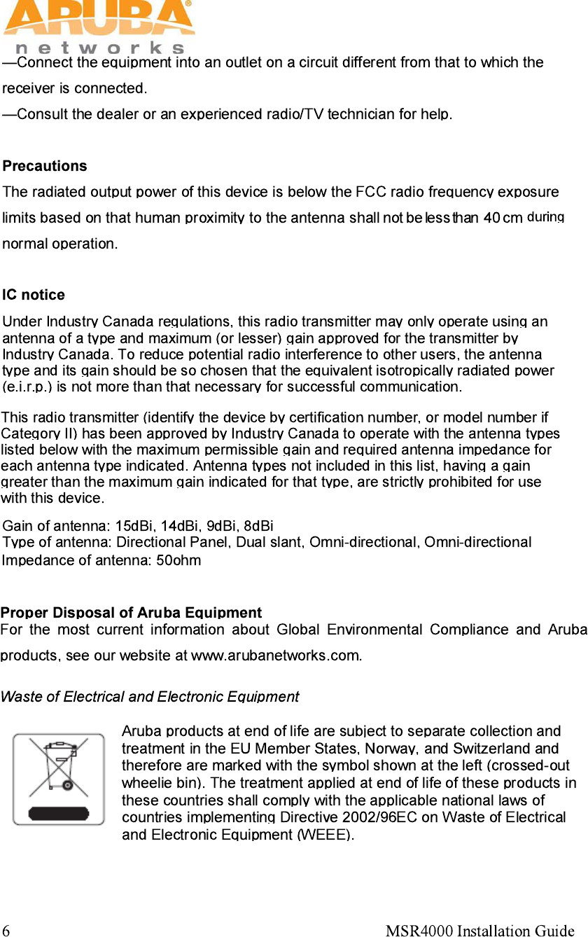
—Reorient or relocate the receiving antenna.
—Increase the separation between the equipment and receiver.
MSR4000 Installation Guide 7
MSR4K43N0
MSR4K43N3
8 MSR4000 Installation Guide

MSR4000 Installation Guide 9
Table of Contents
1 PRODUCT OVERVIEW ............................................................................................................................... 10
1.1 INTERFACES ..................................................................................................................................... 10
1.2 LED STATUS INDICATORS ................................................................................................................. 11
2 INSTALLATION PREPARATIONS ............................................................................................................. 14
2.1 PACKAGE CONTENTS ........................................................................................................................ 14
2.2 PREPARING INSTALLATION TOOLS ..................................................................................................... 14
2.3 EXAMINING THE INSTALLATION SITE ................................................................................................... 15
3 WEATHERPROOFING CONNECTIONS .................................................................................................... 16
3.1 REQUIRED ITEMS AND TOOLS ............................................................................................................ 16
3.2 TYPES OF CONNECTIONS .................................................................................................................. 16
3.3 IMPORTANT POINTS TO REMEMBER ................................................................................................... 18
3.4 WEATHERPROOFING DIRECTLY CONNECTED ANTENNAS .................................................................... 18
3.5 WEATHERPROOFING CABLE CONNECTIONS ....................................................................................... 21
4 MSR4000 INSTALLATION .......................................................................................................................... 25
4.1 INSTALLING MSR4000 ON A POLE ..................................................................................................... 25
4.2 INSTALLING MSR4000 ON A WALL ..................................................................................................... 29
4.3 GROUNDING THE MSR4000 ............................................................................................................. 31
4.4 CONNECTING THE RF CABLE ............................................................................................................. 31
4.5 CONNECTING THE ETHERNET CABLE .................................................................................................. 32
4.6 CONNECTING POWER CABLE ............................................................................................................. 34
5 NOTE ........................................................................................................................................................... 36
10 MSR4000 Installation Guide
1 Product Overview
There are two versions of the MSR4000, which mainly differ in the way they receive power.
MSR4K43N0: PoE powered
MSR4K43N3: AC powered (100-240VAC)
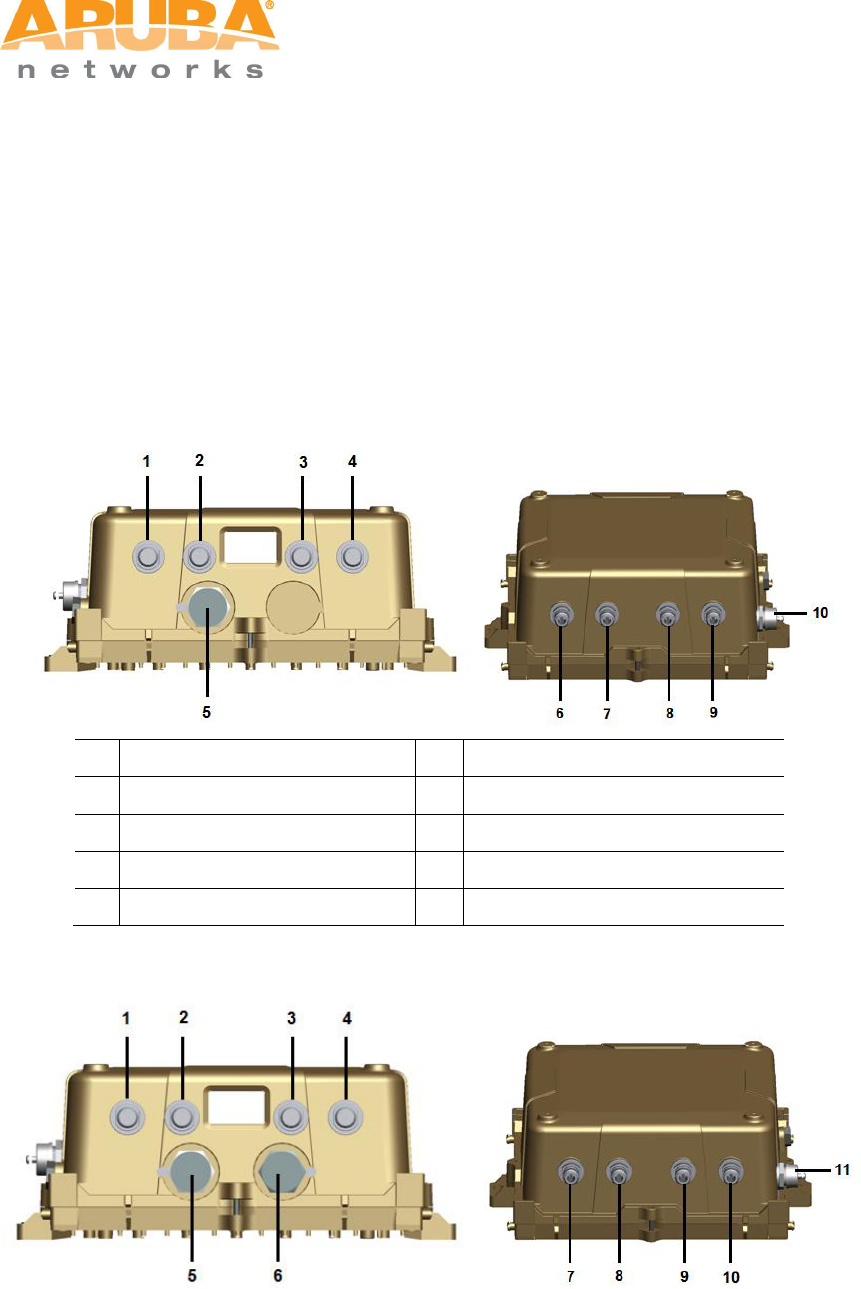
1.1 Interfaces
Figure 1-1 Interfaces on MSR4K43N0
1
Antenna 2 (Radio 0)
6
Antenna 1 (Radio 2)
2
Antenna 2 (Radio 3)
7
Antenna 1 (Radio 1)
3
Antenna 2 (Radio 1)
8
Antenna 1 (Radio 3)
4
Antenna 2 (Radio 2)
9
Antenna 1 (Radio 0)
5
Ethernet Interface
10
Console Interface
Figure 1-2 Interfaces on MSR4K43N3
MSR4000 Installation Guide 11
1
Antenna 2 (Radio 0)
7
Antenna 1 (Radio 2)
2
Antenna 2 (Radio 3)
8
Antenna 1 (Radio 1)
3
Antenna 2 (Radio 1)
9
Antenna 1 (Radio 3)
4
Antenna 2 (Radio 2)
10
Antenna 1 (Radio 0)
5
Ethernet Interface
11
Console Interface
6
AC Power Interface
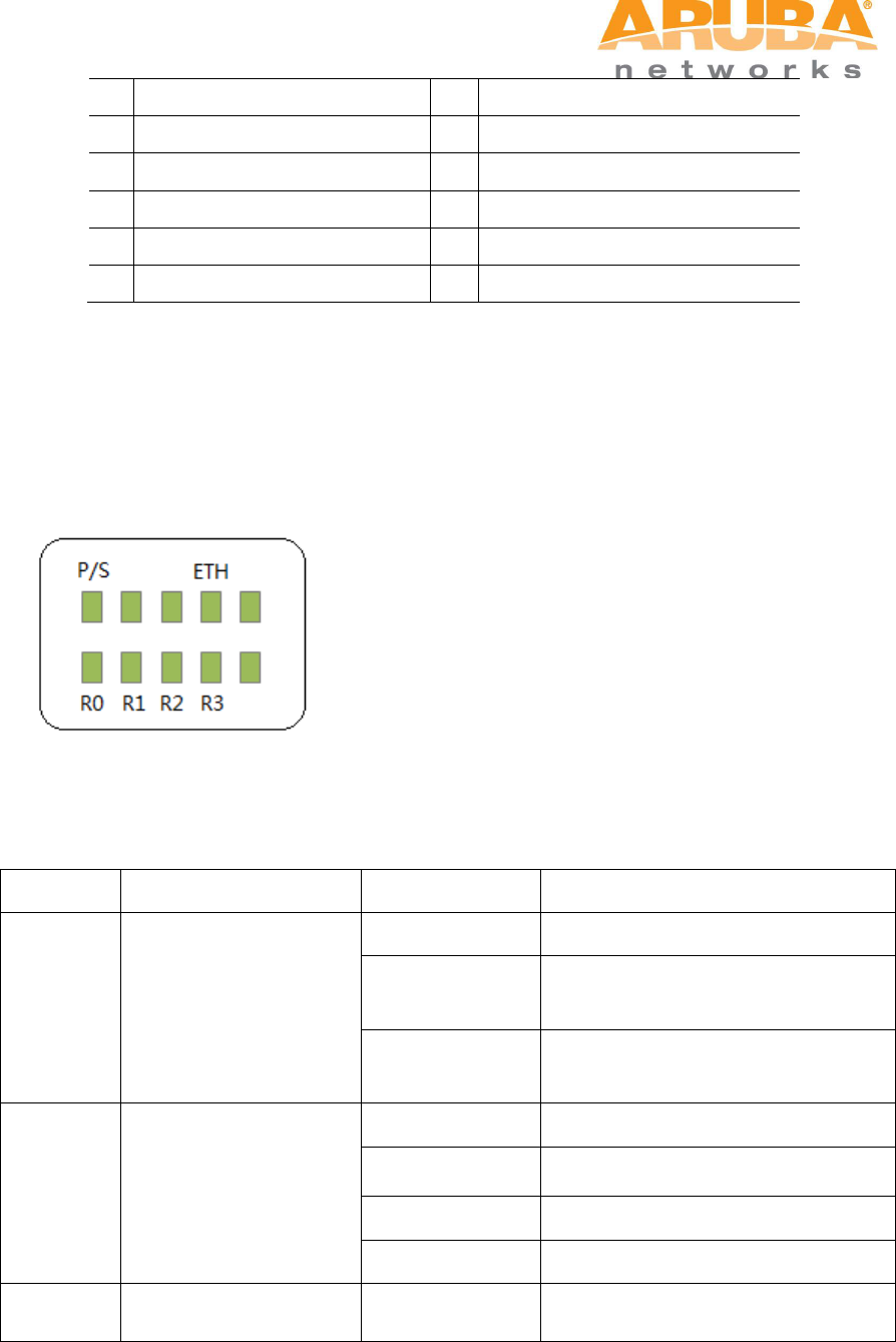
1.2 LED Status Indicators
The MSR4000 include visual indicators for power, link and radio status.
Figure 1-3 MSR4K43N0 LED layout
The table below lists the meanings of the LEDs on the MSR4K43N0.
Table 1-1 MSR4K43N0 LED status indicators
LED
Function
Indicator
Status
P/S
Power
Off
No power to device
On (Amber)
Device has power but does not yet
have a mesh network routing path
to a gateway (portal) node
On (Green)
Device has power and has found a
mesh network routing path to a
gateway (portal) node
ETH
Network Link Status
Off
No uplink on the Ethernet port
On (Amber)
10/100 Mbps Ethernet link
negotiated
On (Green)
1000 Mbps Ethernet link negotiated
Blinking
Traffic on Ethernet link
R0
Radio 0 Status
Off
Radio 0 is not providing either
access (SSID) or backhaul (mesh)
12 MSR4000 Installation Guide
service
On (Blue)
Radio 0 is providing access (SSID)
service or backhaul (mesh) service
R1
Radio 1 Status
Off
Radio 1 is not providing either
access (SSID) or backhaul (mesh)
service
On (Blue)
Radio 1 is providing access (SSID)
service or backhaul (mesh) service
R2
Radio 2 Status
Off
Radio 2 is not providing either
access (SSID) or backhaul (mesh)
service
On (Blue)
Radio 2 is providing access (SSID)
service or backhaul (mesh) service
R3
Radio 3 Status
Off
Radio 3 is not providing either
access (SSID) or backhaul (mesh)
service
On (Blue)
Radio 3 is providing access (SSID)
service or backhaul (mesh) service
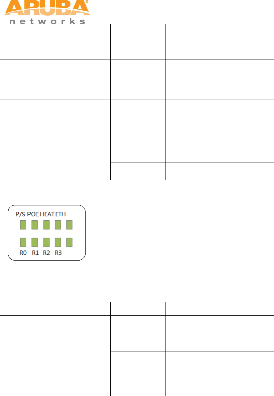
Figure 1-4 MSR4K43N3 LED layout
The table below lists the meanings of the LEDs on the MSR4K43N3.
Table 1-2 MSR4K43N3 LED status indicators
LED
Function
Indicator
Status
P/S
Power
Off
No power to device
On (Amber)
Device has power but does not yet
have a mesh network routing path
to a gateway (portal) node
On (Green)
Device has power and has found a
mesh network routing path to a
gateway (portal) node
POE
Displays PSE power
output status
Off
Non-powered device
(0Ω<Rport<200Ω) or Port open
(Rport>1MΩ)
MSR4000 Installation Guide 13
Green
Port on (25kΩ)
1 Flash: Low signature resistance
(300Ω<Rport<15kΩ)
2 Flashes: High signature
resistance (33kΩ<Rport<500kΩ)
5 Flashes: Port overload fault
9 Flashes: Power management
allocation exceeded
HEAT
Displays the heating
status of low
temperature
Off
Device is not in heating status
Blinking (Blue)
Device is heating
ETH
Network Link Status
Off
No uplink on the Ethernet port
On (Yellow)
10/100 Mbps Ethernet link
negotiated
On (Green)
1000 Mbps Ethernet link negotiated
Blinking
Traffic on Ethernet link
R0
Radio 0 Status
Off
Radio 0 is not providing either
access (SSID) or backhaul (mesh)
service
On (Blue)
Radio 0 is providing access (SSID)
service or backhaul (mesh) service
R1
Radio 1 Status
Off
Radio 1 is not providing either
access (SSID) or backhaul (mesh)
service
On (Blue)
Radio 1 is providing access (SSID)
service or backhaul (mesh) service
R2
Radio 2 Status
Off
Radio 2 is not providing either
access (SSID) or backhaul (mesh)
service
On (Blue)
Radio 2 is providing access (SSID)
service or backhaul (mesh) service
R3
Radio 3 Status
Off
Radio 3 is not providing either
access (SSID) or backhaul (mesh)
service
On (Blue)
Radio 3 is providing access (SSID)
service or backhaul (mesh) service

14 MSR4000 Installation Guide
2 Installation Preparations
This chapter describes the preparations for MSR4000 installation, including checking
package contents, preparing installation tools and selection of installation sites.
2.1 Package Contents
Aruba MSR4000 AirMesh Router
MSR4000 Mounting Bracket x1
Solar Shield x1
Pole Anchors x 4
M4 x 16 bolts, flat washers, and spring washers x4
M4 x 16 bolts x2
M6 x 30 bolts, flat washers, and spring washers x2
M4 x 12 bolt, external-tooth washer, and OT copper lug x1
M8 x 110 bolt, flat washers, spring washers, and nuts x4
Metal Weatherproof Caps x2 for use on unused antenna interfaces
RJ-45 Connector Kit with metal RJ-45
USB Console Cable
Installation Guide
Note
Inform your supplier if there are any incorrect, missing, or damaged parts. If
possible, retain the carton, including the original packing materials. Use
these materials to repack and return the unit to the supplier if needed.
2.2 Preparing Installation Tools
When installing MSR4000, you may need the following tools. You shall select the tools
according to the actual situation.
MSR4000 Installation Guide 15
Table 2-1 Installation tools list
Type
Tools
General tools
Screwdriver, adjustable spanner, vice, safety belt, hard hat, power
board (220 VAC or as required by local regulation), POE power
injector, crimping pliers, electric soldering iron, welding wire, PVC
insulation tape, adhesive insulation tape, strap, insulation tools
2.3 Examining the Installation Site
1. The site should be located within at least a 60% range of the 1st fresnel zone without
obstacles to provide LOS transmission, increase coverage capacity, and minimize
the number of necessary sites.
2. If no LOS secured, area in NLOS area could be covered as well, but the distance of
coverage and area of coverage are decreased; more sites are needed to provide
coverage for same area than in the LOS scenario.
3. Interference must be considered in site selection. New site should avoid known
interference, unless the interference is controllable.
4. Keep the MSR4000 away from places that are susceptible to high temperature, dust,
harmful gas, inflammable, explosive, electromagnetic interference (high power radar,
radio station and transformer), unstable voltage, heavy vibration, or loud noise. In
engineering design, the site should be selected according to the network planning
and technical requirements of communications equipment, as well as the
considerations such as climate, hydrology, geology, earthquake, electric power, and
transportation.

16 MSR4000 Installation Guide
3 Weatherproofing Connections
Weatherproofing your antenna and/or cable connections on your outdoor AP is
essential to reliability and longevity of your product. This process prevents water
from entering the AP or antennas through the connectors.
A good weatherproofing job consists of three wrappings:
1. electrical tape
2. butyl rubber
3. electrical tape
The first wrapping of tape should be at least two layers, followed by a single wrap
of butyl rubber, and four-layer wrap of electrical tape. This provides good
protection from water, heat, and other potential hazards that could damage your
AP or antennas.
Additionally, wrap your connections such that water is always directed down and
away from connections.
3.1 Required Items and Tools
3/4” (19 mm) Vinyl Electrical Tape (waterproofing type)
Butyl Rubber Tape
Knife or Box Cutter
3.2 Types of Connections
The following sections provide guidance on weatherproofing directly connected
antennas (Figure 3-1) and cable connections (Figure 3-2). The same materials
are needed for weatherproofing both types of connections but the procedure is
slightly different. For weatherproofing directly connected antennas, see
MSR4000 Installation Guide 17
"Weatherproofing Directly Connected Antennas" section. For weatherproofing
cable connections, see "Weatherproofing Cable Connections" section.
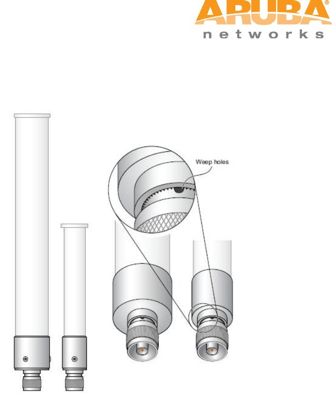
Figure 3-1 Directly connected antennas
18 MSR4000 Installation Guide
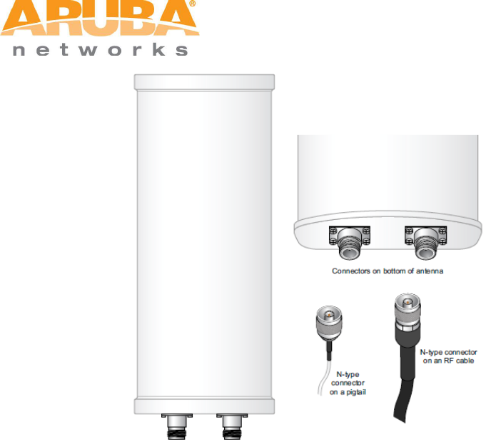
Figure 3-2 Cable connections
3.3 Important Points to Remember
Do not cover the weep holes on the antennas. Doing so can restrict the
release of condensation from the antennas.
Proper weatherproofing is not a fast process. Set aside ample time to
complete the steps outlined below.
When wrapping, make the each layer of tape as flat as possible. Wrinkles
and folds in the tape create places for water and moisture to gather.
3.4 Weatherproofing Directly Connected Antennas
First Wrapping of Tape
1. Before wrapping the antennas, locate the weep holes (Figure 3-1). Weep
holes allow condensation that has built up inside the antenna to escape.
2. Prepare the antenna connector by cleaning and drying it.
3. Cut a 4” (100 mm) strip of electrical tape from the roll. Pre-cutting the tape
into strips makes it easier to maneuver the tape around the antennas and
other components of the AP’s case.
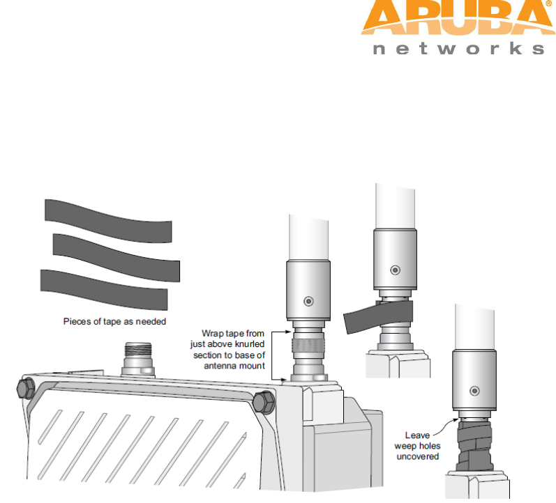
MSR4000 Installation Guide 19
4. Beginning just below the weep holes, tightly wrap the connection with a layer
of the 3/4” (19mm) electrical tape. Overlap the tape to a half-width.
5. Repeat steps 3 and 4 until the wrapping extends all the way to the AP’s case.
Figure 3-3 First Wrapping of Tape
Wrapping of Butyl Rubber
1. Cut a 3/4” (19 mm) strip of butyl rubber.
2. Wrap the strip of rubber around the taped connector (Figure 3-4)
3. Join the two ends by pushing them together until there is no longer a seam
(Figure 3-5).
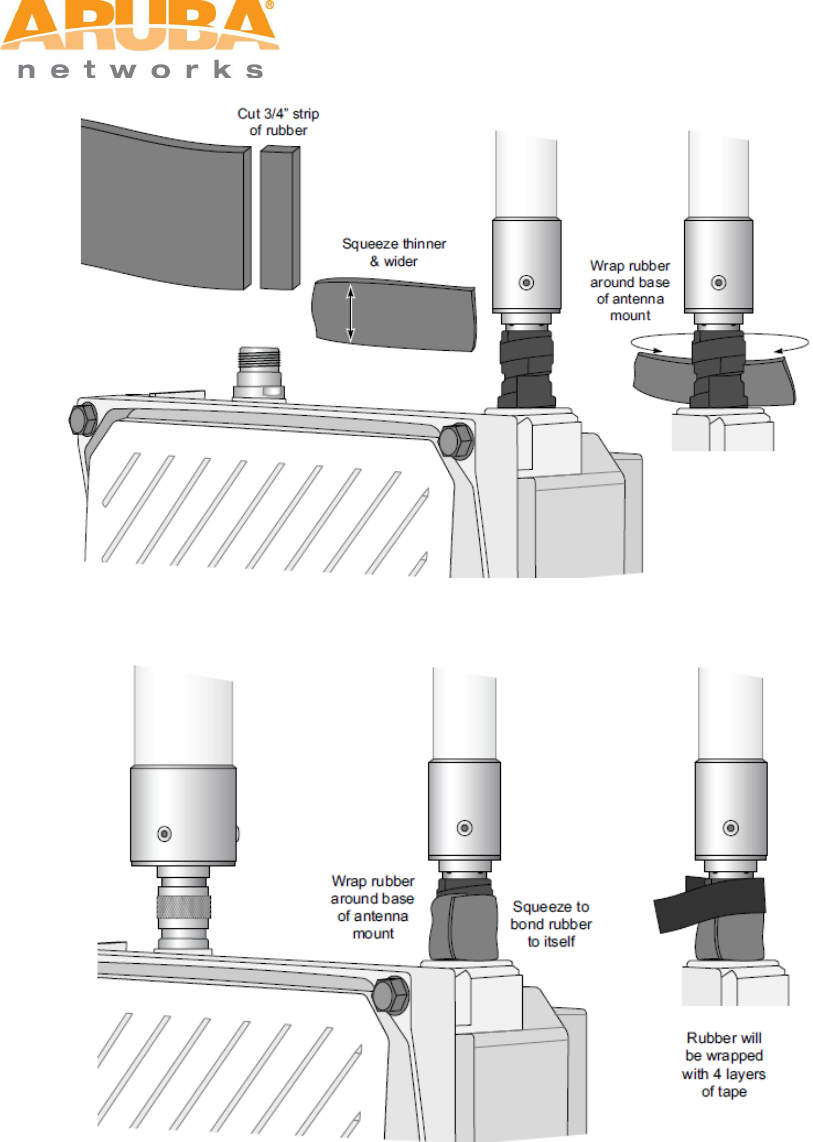
20 MSR4000 Installation Guide
Figure 3-4 Butyl rubber placement
Figure 3-5 Butyl rubber wrap
Second Wrapping of Tape
1. Cut a 4” (100 mm) strip of electrical tape from the roll.
2. Where you begin wrapping depends on the orientation of the antenna. Water
should flow in the opposite direction of the wrapping to prevent water from
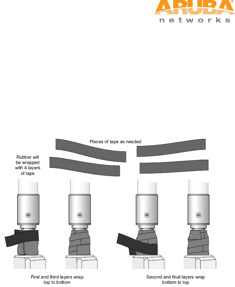
MSR4000 Installation Guide 21
entering the connector between the layers of tape. Therefore, if the antenna
is facing up, you should begin wrapping at the AP end of the connector. This
will ensure that your fourth and final layer will be layered correctly.
Conversely, if your antenna is facing down, you should begin wrapping on
the antenna end of the connector.
3. After completing the fourth layer of tape, check your work to ensure there are
no places where water can collect. If there are, you must smooth out those
areas with additional layers of tape or remove the weatherproofing and begin
again.
Figure 3-6 Completed wrapping (antenna on top of AP)
4. Repeat this process for all connectors.
3.5 Weatherproofing Cable Connections
First Wrapping of Tape
1. Prepare the antenna connector by cleaning and drying it.
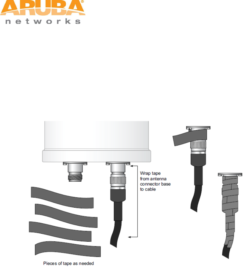
22 MSR4000 Installation Guide
2. Cut a 4” (100 mm) strip of electrical tape from the roll. Pre-cutting the tape
into strips makes it easier to maneuver the tape around the connectors and
other components but is not required.
3. Beginning at the top of the connector, tightly wrap the connection with a layer
of the 3/4” (19mm) electrical tape. Overlap the tape to a half-width.
4. Repeat steps 3 and 4 until the wrapping extends all the way to the cable’s
insulation.
Figure 3-7 First wrapping of tape
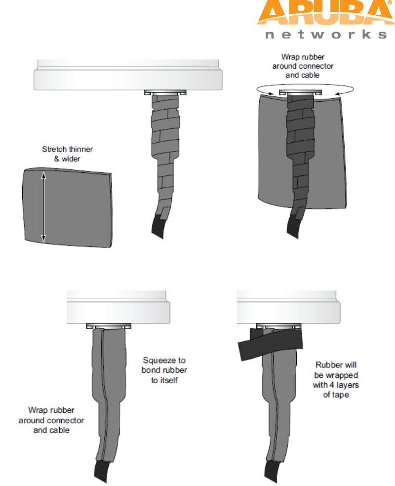
Wrapping of Butyl Rubber
1. Cut a piece of butyl rubber large enough to wrap around the connector and
extended past the first layer of tape.
2. Wrap the strip of rubber around the taped connector (Figure 3-8)
3. Join the two ends by pushing them together until there is no longer a seam
(Figure 3-9).
MSR4000 Installation Guide 23
Figure 3-8 Butyl rubber placement
Figure 3-9 Butyl rubber wrap
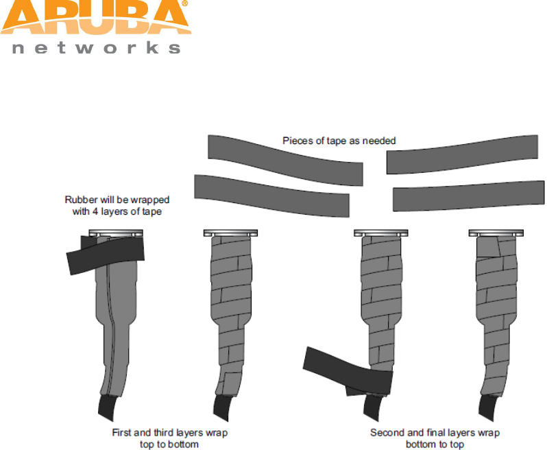
Second Wrapping of Tape
1. Cut a 4” (100 mm) strip of electrical tape from the roll.
2. Using 3/4” (19mm) electrical tape, begin wrapping at the connector and
create four layers.
3. After completing the fourth layer of tape, check your work to ensure there are
no places where water can collect. If there are, you must smooth out those
24 MSR4000 Installation Guide
areas with additional layers of tape or remove the weatherproofing and begin
again.
Figure 3-10 Completed wrapping
4. Repeat this process for all connections.
MSR4000 Installation Guide 25
4 MSR4000 Installation
4.1 Installing MSR4000 on a pole
The mounting bracket assembly for installing MSR4000 concludes: solar shield, a pair of
pole anchors, a mounting bracket and bolts. MSR4000 can be mounted on a pole or wall.
(Pole diameter must be 40 to 60 mm at the position where the MSR4000 will be mounted.)
Note
If using M8 x150 long bolts (not provided in the box shipped with MSR4000), the
MSR4000 can be mounted on a pole with 96mm diameter.
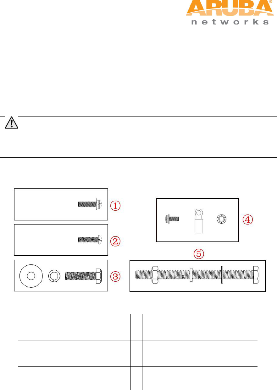
Figure 4-1 Bolts
1
{M4 x16 bolt (flat washer, spring
washer)}x4
4
{M4 x12 bolt, external-tooth washer,
OT copper lug}x1
2
{M4 x16 bolt}x2
5
{M8 x110 bolt, flat washer, spring
washer, nut}x4
3
{M6 x30 bolt, flat washer, spring
washer}x2
Step 1 Fix the solar shield on MSR4000 using the four M4 x16 bolts (with flat and spring
washers) on the four screw holes of the MSR4000. (See figure below)
26 MSR4000 Installation Guide
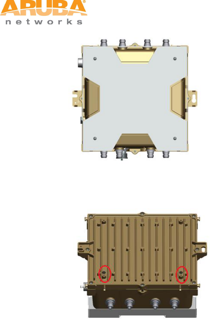
Figure 4-2 Positions of screw holes on the solar shield
Step 2 Screw the two M4 x16 bolts into the holes on the back of the MSR4000. (See figure
below)
Figure 4-3 Positions of screw holes on the back of the MSR4000
Step 3 Fix the mounting bracket and the pair of pole anchors on the pole using four M8 x110
bolts (with flat washers, spring washers and nuts).
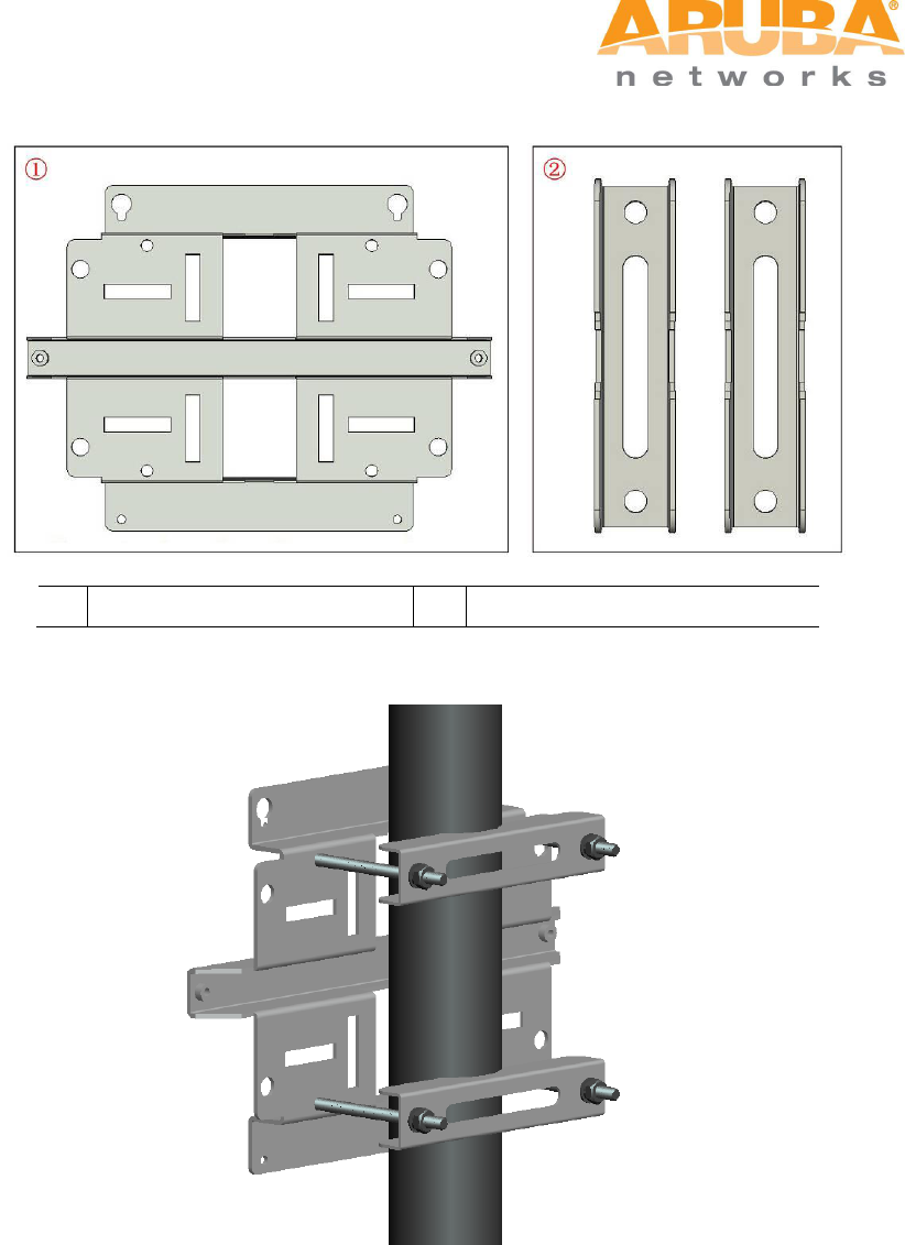
MSR4000 Installation Guide 27
Figure 4-4 the pole anchors and mounting bracket
1
A mounting bracket
2
A pair of pole anchors
Figure 4-5 Fix the mounting bracket and the pair of pole anchors on the mounting bracket
Step 4 Align the two M4 x16 bolts on the back of MSR4000 with the holes on the mounting
bracket and hang the MSR4000 on the bracket.
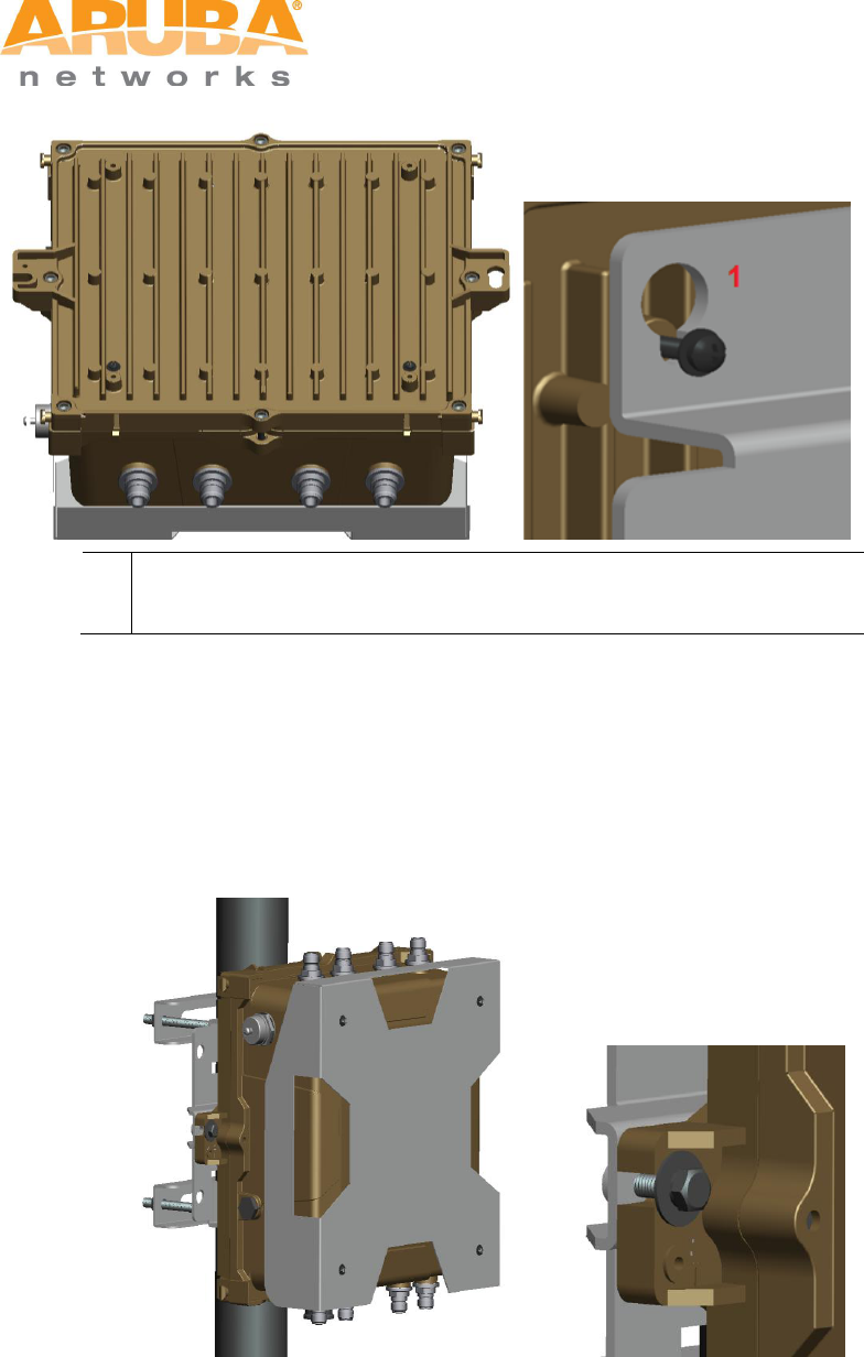
28 MSR4000 Installation Guide
Figure 4-6 Fix the MSR4000 on the bracket
1
Hang the two M4 x16 bolts of the back of the MSR4000 on the two
holes of the mounting bracket.
Step 5 Align the two installation holes on the side of the MSR4000 with the corresponding
holes on the mounting bracket and then use the two M6 x30 bolts (with flat and
spring washers) to fix them. (There is screw thread in the screw hole of the solar
shield)
Figure 4-7 Fix MSR4000 on the bracket
MSR4000 Installation Guide 29
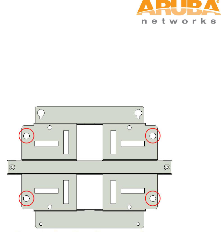
4.2 Installing MSR4000 on a wall
Step 1 Mark
1) Put the mounting bracket on the installation position against the wall.
2) Mark four expansion screw holes on the wall.
Figure 4-8 Positions of screw holes
Step 2 Drill holes
1) Use a percussion drill to drill four holes on the four markings. (Expansion screw size: M8 x
100mm)
Step 3 Install masonry anchors
1) Insert a masonry anchor into each drilled hole vertically.
2) Tap the flat end of the anchor with a rubber hammer until the anchor is flush with the wall
surface.
Step 4 Fix the wall-mounting bracket
1) Align the four holes in the wall-mounting bracket with the anchors and insert four
expansion screws through the installation holes into the anchors.
2) Adjust the position of the wall-mounting bracket and tighten the expansion screws.
Step 5 Hang the MSR4000 on the bracket
1) Screw the two M4 x16 bolts into the holes on the back of the MSR4000.
2) Align the two M4 x16 bolts on the back of MSR4000 with the holes on the mounting
bracket and hang the MSR4000 on the bracket.
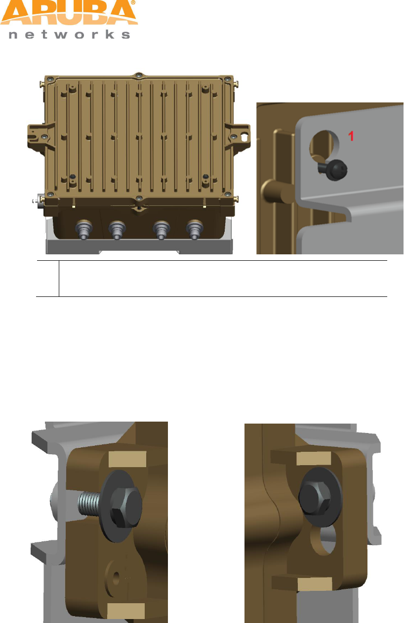
30 MSR4000 Installation Guide
Figure 4-9 Positions of the two M4 x16 bolts and the holes
1
Hang the two M4 x16 bolts of the back of the MSR4000 on the two
holes of the mounting bracket.
Step 6 Fix MSR4000
1) Align the two installation holes in the MSR4000 with the corresponding holes in the wall-
mounting bracket.
2) Insert the two M6 x30 bolts (with flat and spring washers) through the installation holes,
and tighten the bolts.
Figure 4-10 Positions of installation holes
Left side Right side
MSR4000 Installation Guide 31
4.3 Grounding the MSR4000
The grounding must be completed before powering up the MSR4000.The residence of
grounding wire should be less than 5 ohm and the grounding cable’s cross-section area
should be no less than 6 mm2.The grounding hole is at the left side of the MSR4000.
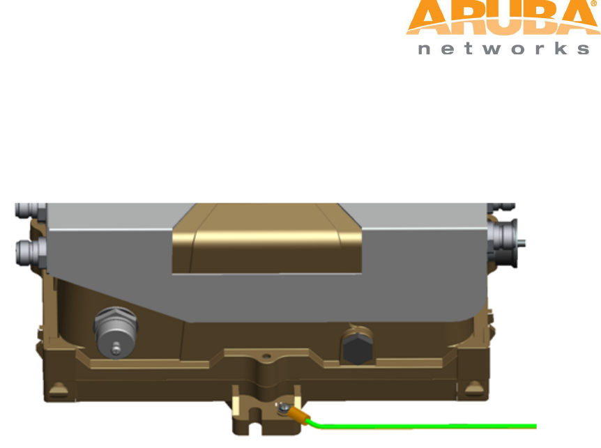
Figure 4-11 Grounding the MSR4000
Step 1 Peel the cover of one end of the grounding cable (green or yellow and green
grounding cable) and place the bare grounding cable into the copper lug, and press
firmly with the crimping pliers.
Step 2 Fasten the copper lug to the grounding hole on the MSR4000 with the M4 x12 bolt
and external-tooth washer.
4.4 Connecting the RF cable
The RF cable is used to connect antenna and the MSR4000. (Note: you should install
lightning arrester between antenna and the MSR4000.)
32 MSR4000 Installation Guide
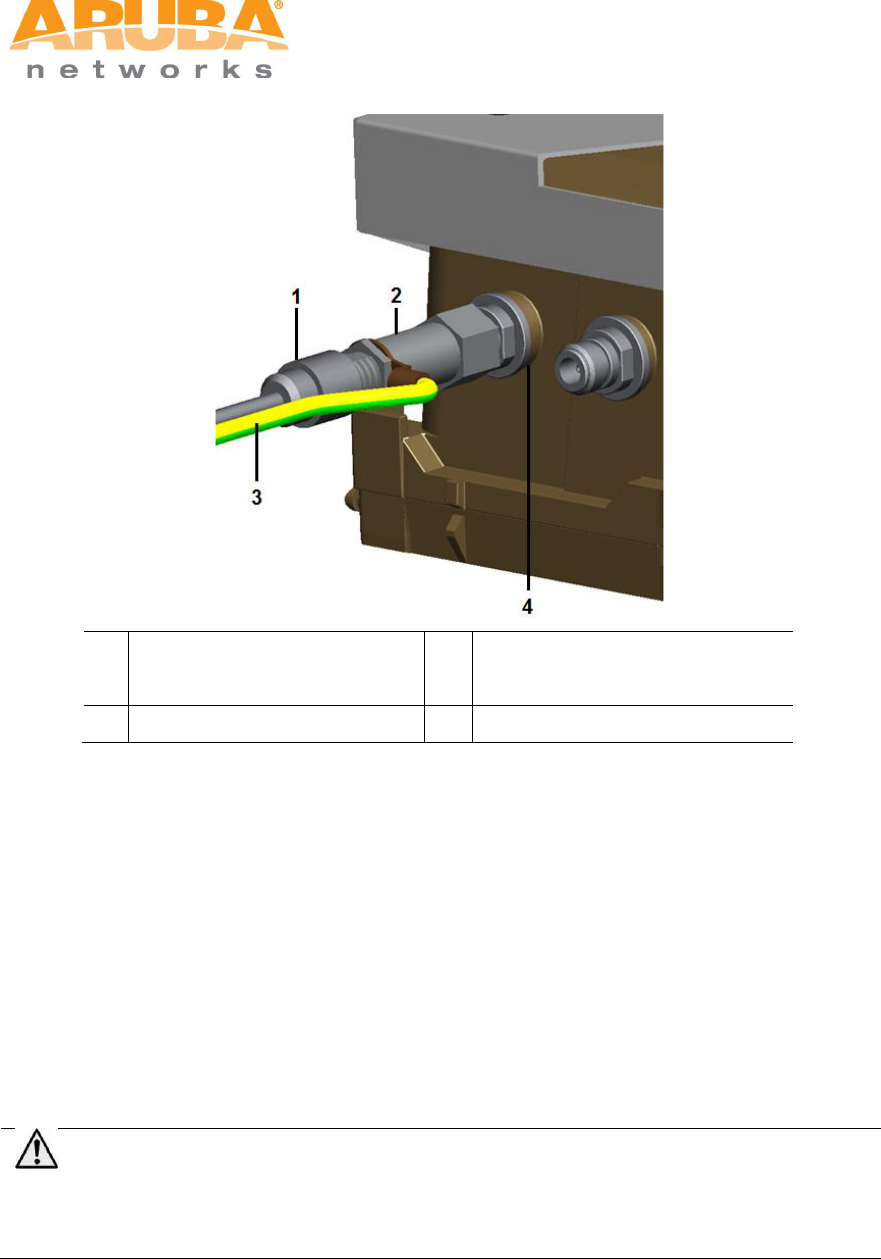
Figure 4-12 Connecting the RF cable
1
RF cable
3
Grounding cable for lightning
arrester
2
lightning arrester
4
Antenna interface
Step 1 Screw one end of the lightning arrester onto the antenna interface.
Step 2 Connect the RF cable to the other end of the lightning arrester.
Step 3 Water-proof the antenna connection with PVC insulation tape, adhesive insulation
tape and strap.
4.5 Connecting the Ethernet cable
To ensure that MSR4000 maintains Ethernet connectivity and Power over Ethernet (PoE),
you must use the weatherproof connector kit and install it using the steps below.
Note
Failure to use the included weatherproof connector kit can lead to connectivity and PoE
issues.
MSR4000 Installation Guide 33
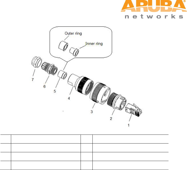
Figure 4-13 Weatherproof Connector Kit
1
Shielded RJ45 connector
5
Shield rings
2
Waterproof connector socket
6
Sealing bolt
3
Locknut
7
Sealing nut
4
Clamp ring
1. Hold the clamp ring (4) vertically, with the wide end facing up, and place the locknut (3)
over it.
2. Drop the waterproof connector socket (2) into the locknut/clamp ring items (3,4), with the
RJ45 connector opening facing up, and screw the socket into the threads on the clamp
ring.
3. Place the sealing nut (7) over an Ethernet cable (without a connector attached to the
end).
4. Place the seal bolt (6) over the Ethernet cable.
5. Strip off about 55mm (2 inches) of the outer Ethernet cable sheath to expose the ground
wire and other pair wires.
6. Insert all pair wires into the two shield rings (5).
7. Make the ground wire attach to the narrow end of the inner ring and place the outer ring
over the narrow end of the inner ring.
8. Insert the Ethernet cable into the narrow end of the clamp ring and pass it through the
opening end of waterproof connector socket.
9. Using a crimping tool, attach the included shielded RJ45 connector.
34 MSR4000 Installation Guide
10. Slide the shield rings up the Ethernet cable and insert it into the narrow end of the clamp
ring.
11. Pull the Ethernet cable so the shielded RJ45 connector fits into the RJ45 shaped
opening in the wide end of the weatherproof connector socket.
12. Slide the sealing bolt over the narrow end of the clamp ring and hand tighten it.
13. Thread the sealing nut onto the sealing bolt.
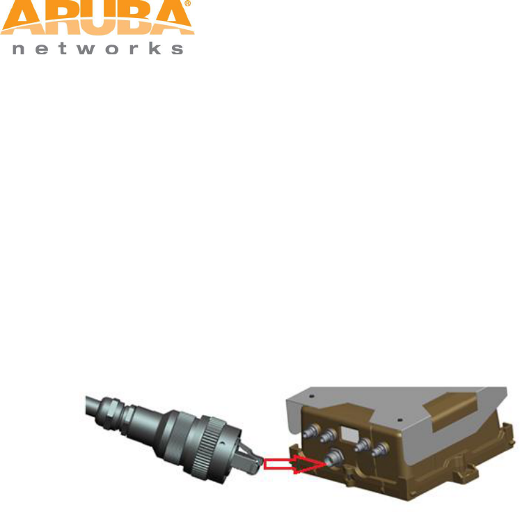
14. Insert the Ethernet cable connector into the Ethernet interface and hand-tighten the
locknut.
15. Water-proof the Ethernet cable connection with PVC insulation tape and adhesive tape.
Figure 4-14 Connecting Ethernet cable to the Ethernet interface
4.6 Connecting power cable
The MSR4K43N3 version needs an outdoor rated power cable to connect to a compatible
AC power source.
Note: The MSR4000 does not ship with any power cables; these are available as
accessories and should be ordered separately. In addition to completed power cables, Aruba
also offers an outdoor rated AC connector kit that can be used to connect a compatible
power cable to the MSR4000.
AC power source specifications (at MSR4000 interface): 100-240Vac, 100W
AC power cable specifications (when using CKIT-AC-M connector kit): minimum
voltage/current rating 250V/1A, diameter 6-12mm, rated for outdoor use
Cable connection steps:
Step 1 Remove the protective cap on the power interface.
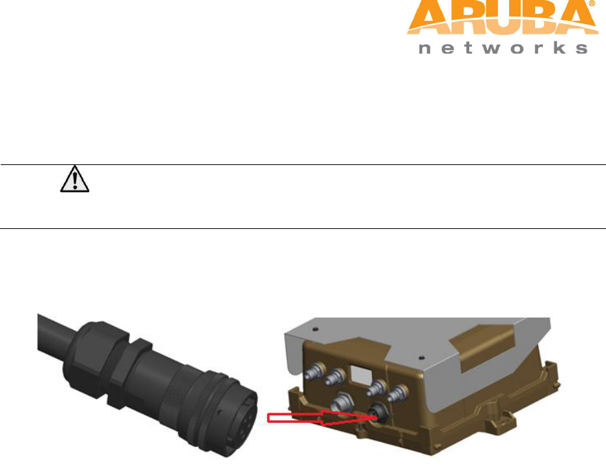
MSR4000 Installation Guide 35
Step 2 Insert the power cable connector into the power interface and hand-fasten the
waterproof cover.
Step 3 Water-proof the power cable connection with PVC insulation tape, adhesive
insulation tape and strap.
Note
Cable assembly and installation should be done by a licensed electrician only.
Figure 4-15 Connecting power cable to the power interface
36 MSR4000 Installation Guide
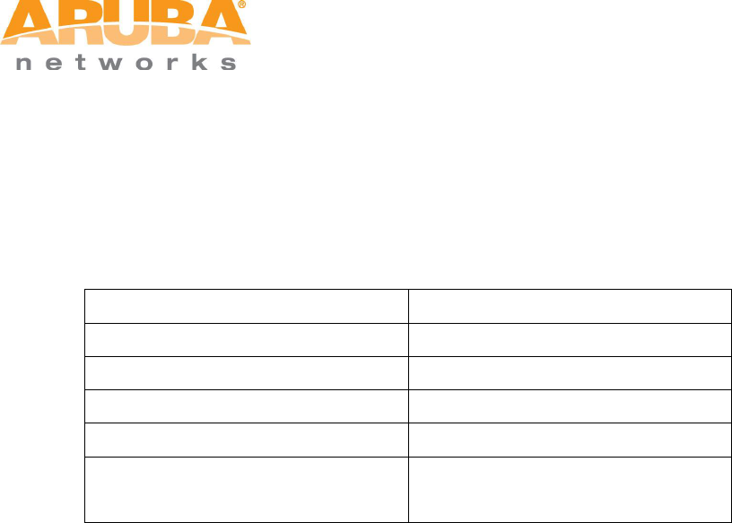
5 Note
To log onto the MSR4000 via Console port, use the setting as shown in table
below:
Baud Rate
115200
Data Bits
8
Parity
None
Stop Bits
1
Flow Control
None
Default Username and Password
Username: root
Password: public