Hewlett Packard Enterprise MSR4000DFS Outdoor 802.11a/b/g/n Access Point User Manual MSR4000 Series IG Rev 02
Aruba Networks, Inc. Outdoor 802.11a/b/g/n Access Point MSR4000 Series IG Rev 02
Contents
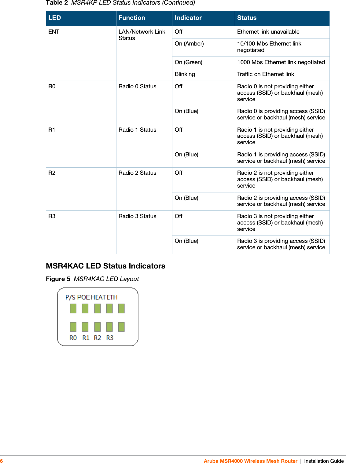
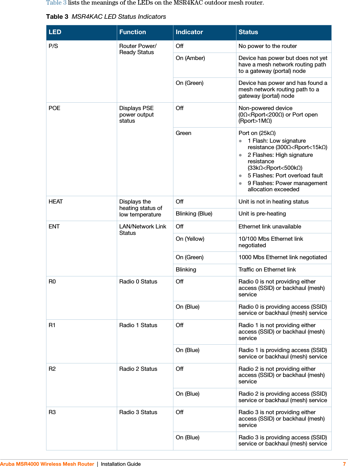
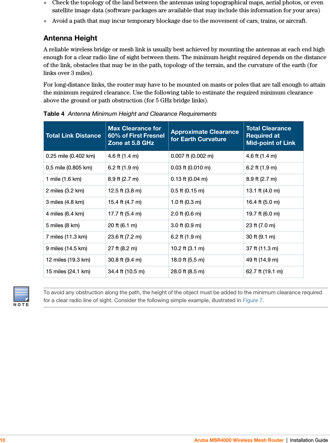
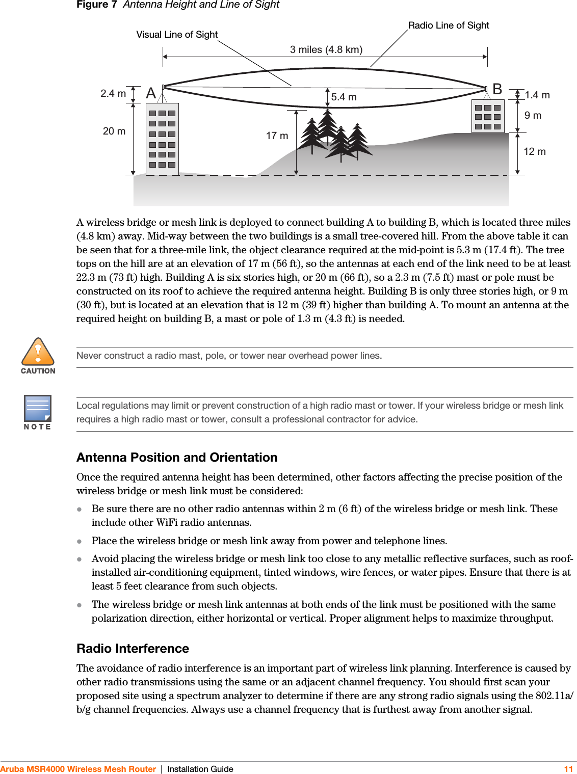
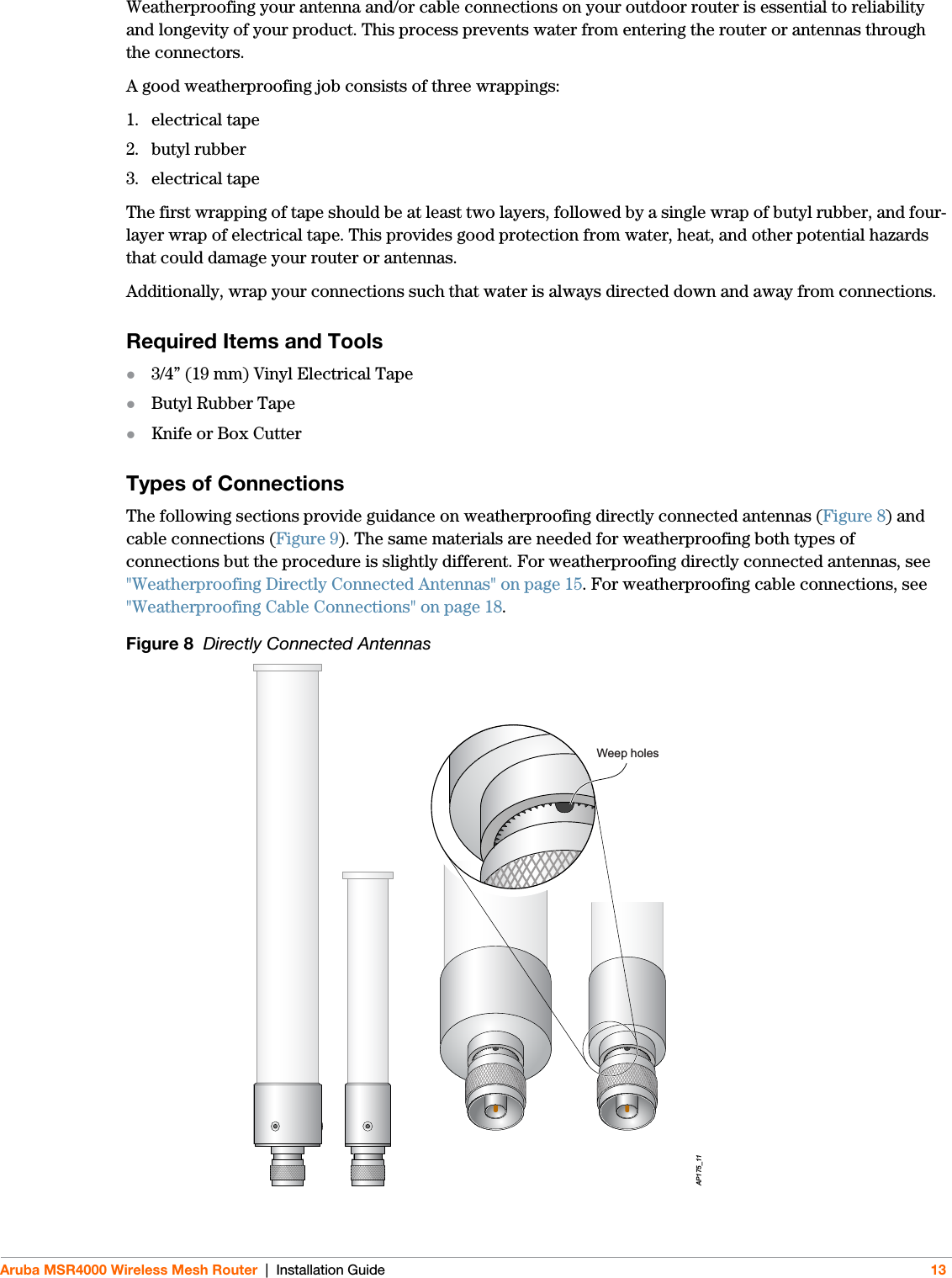
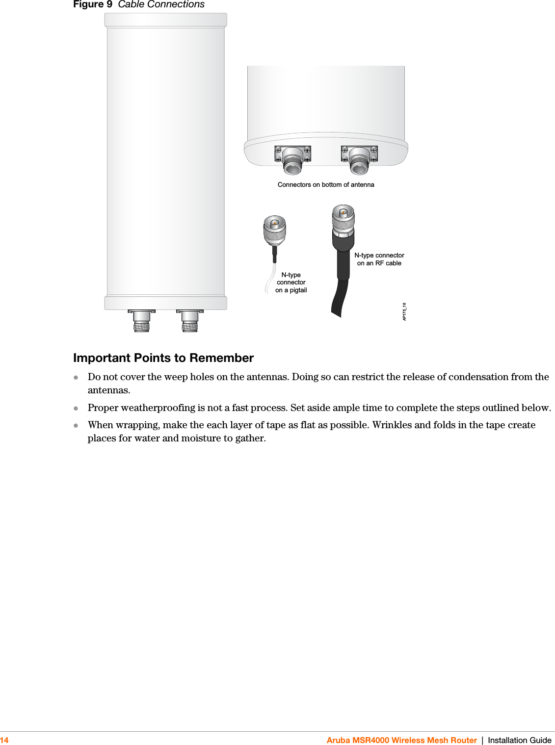
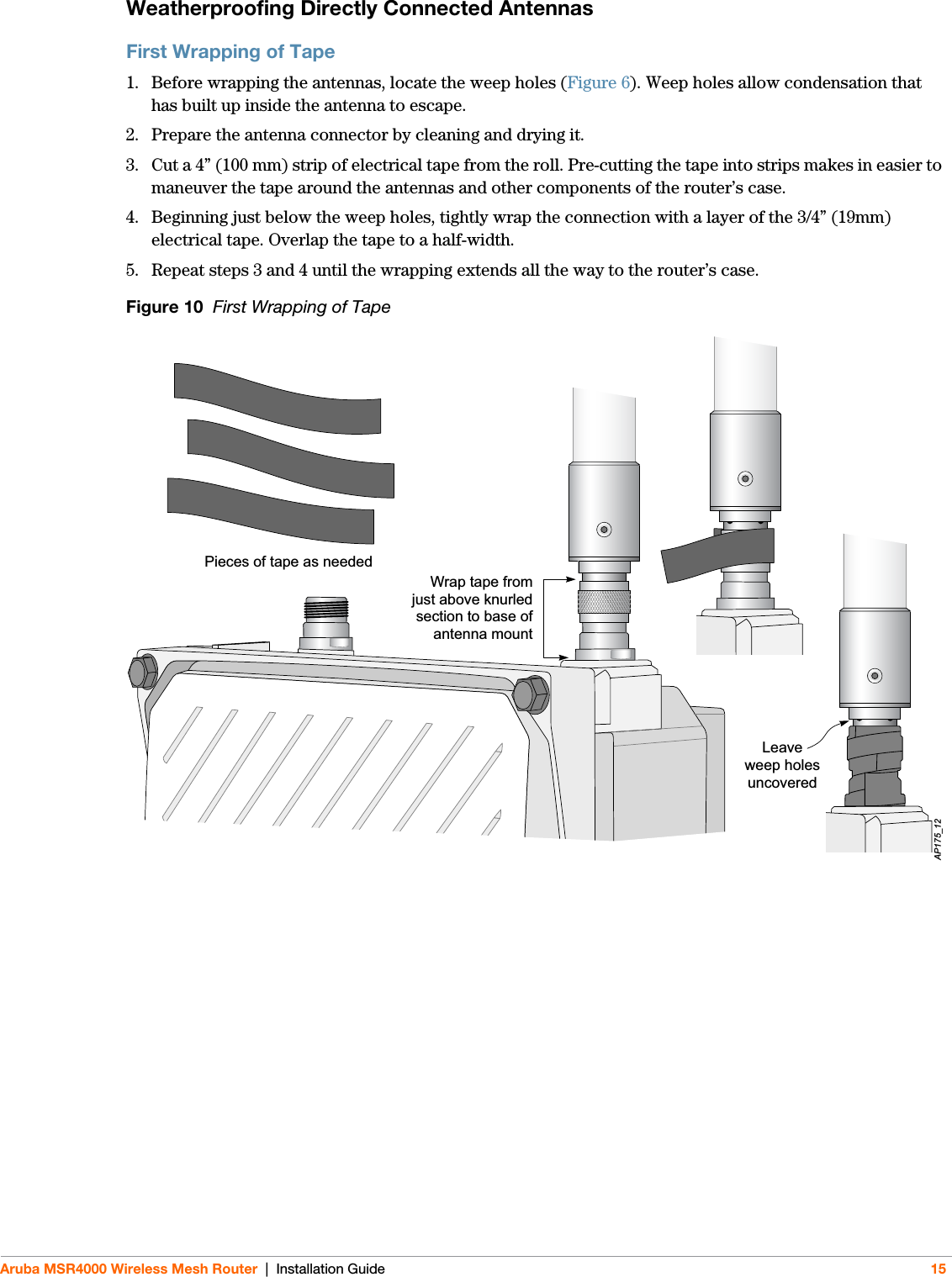
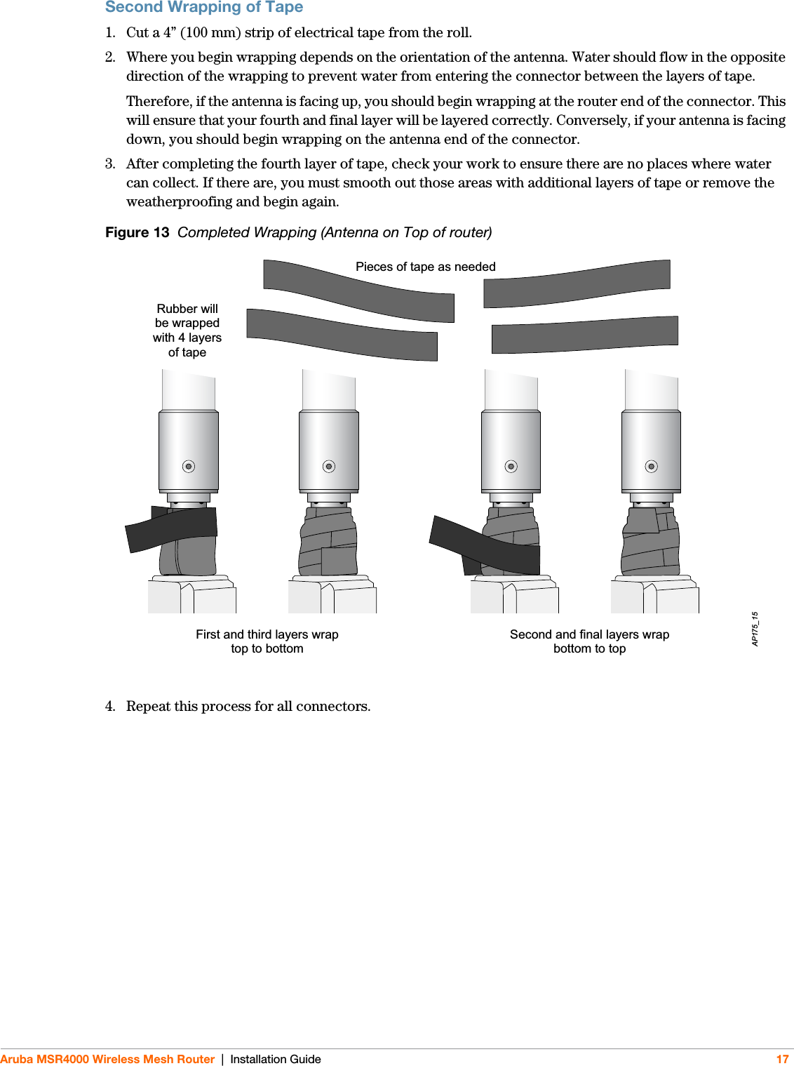
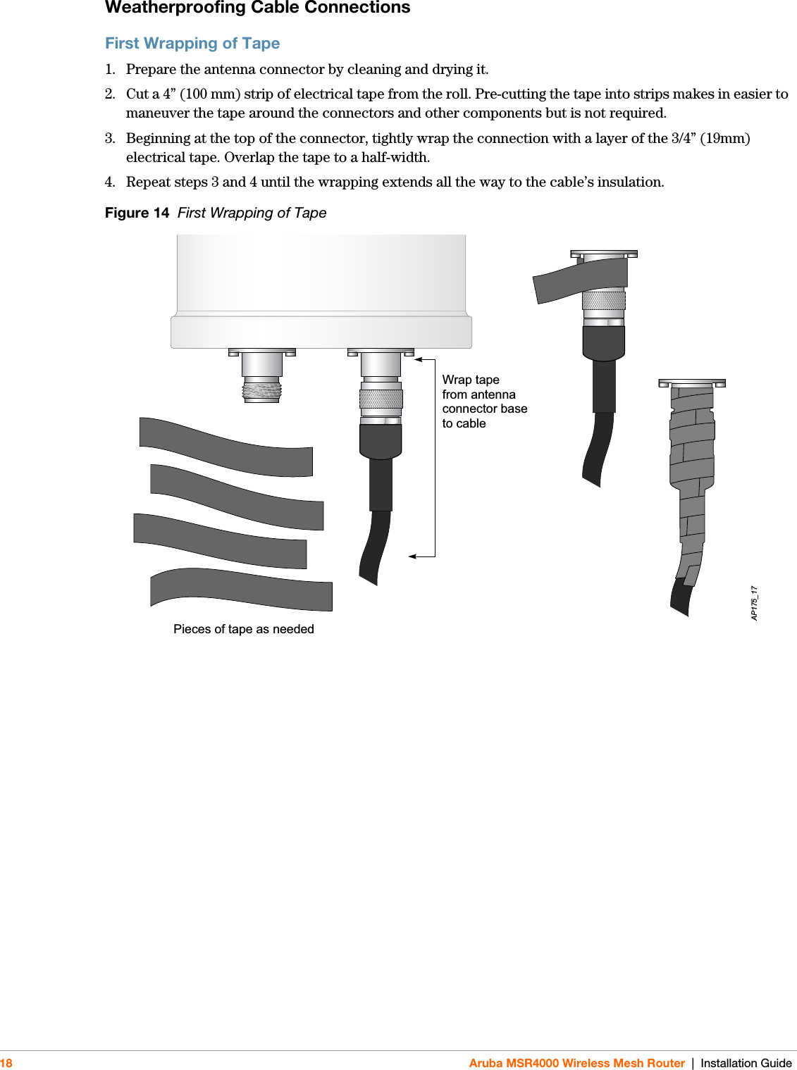
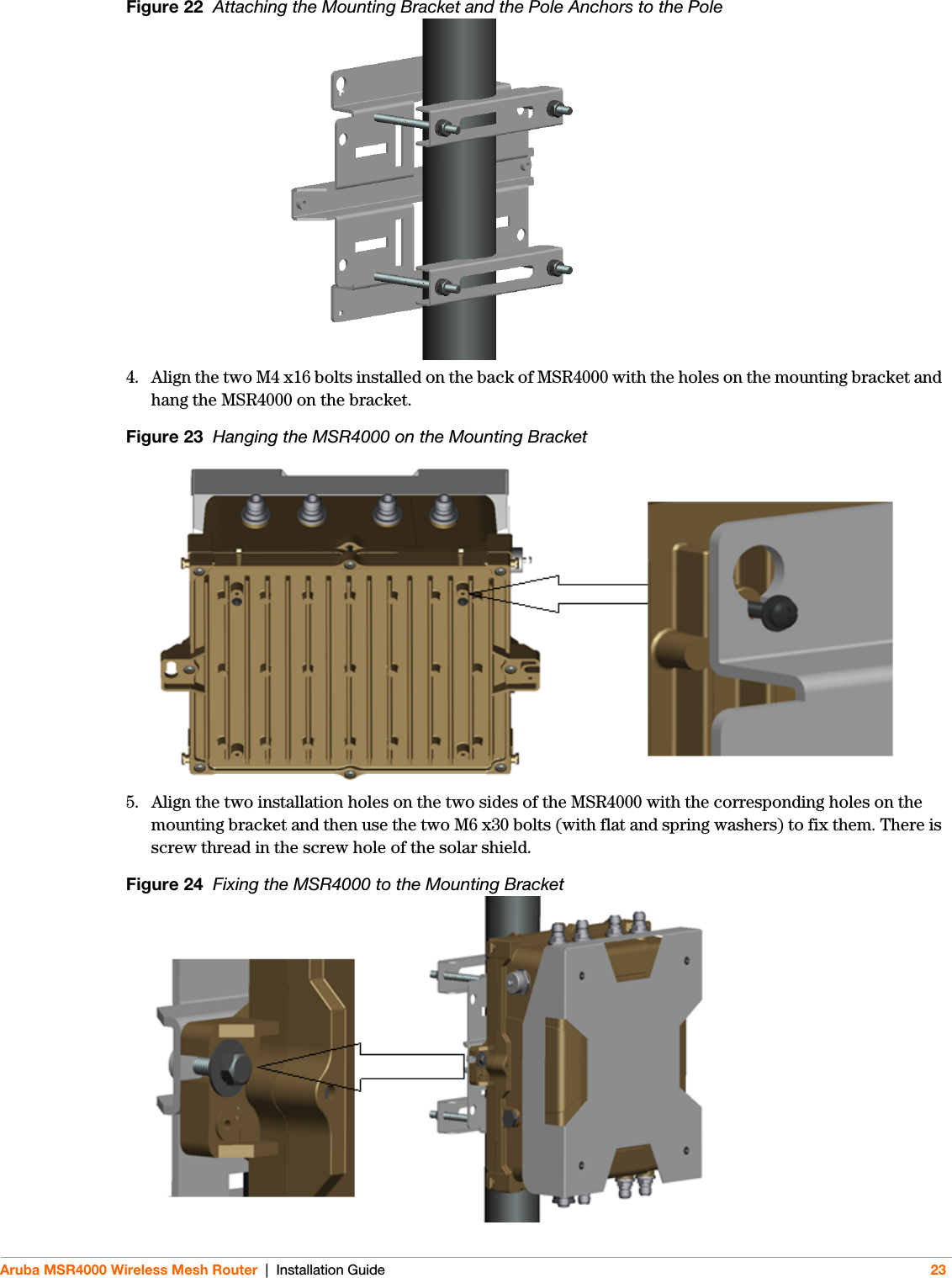
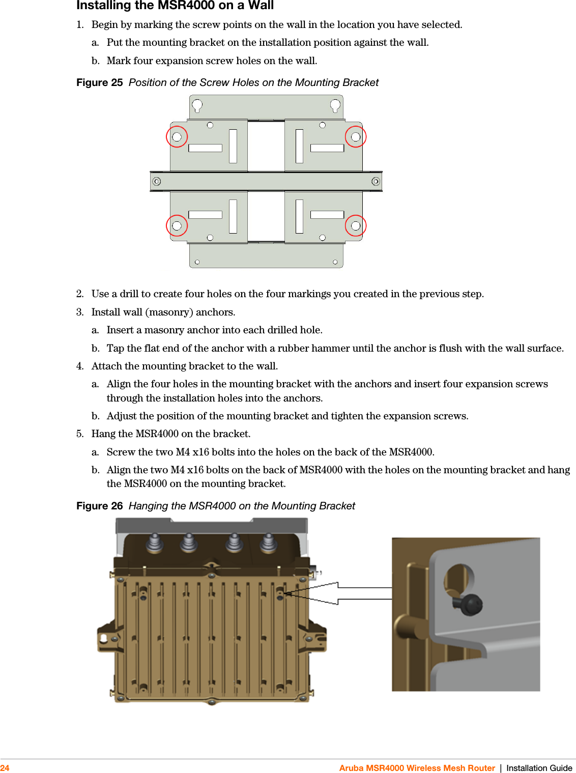
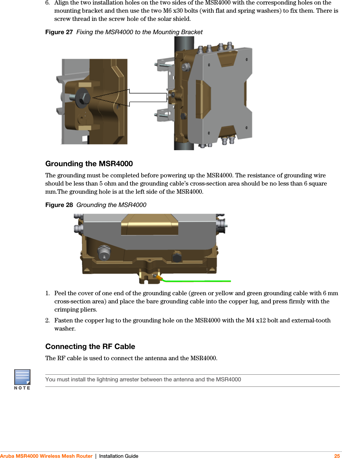
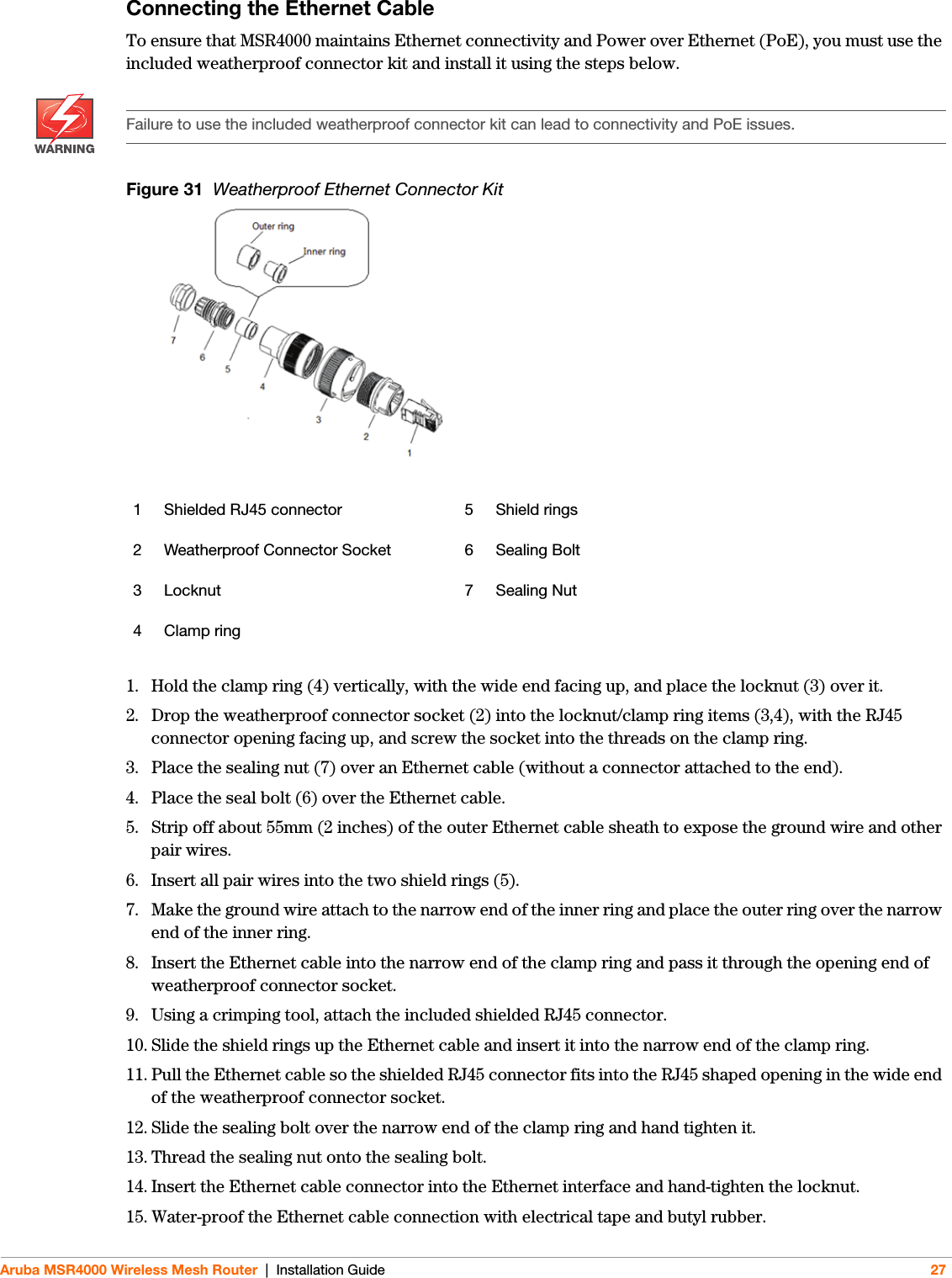
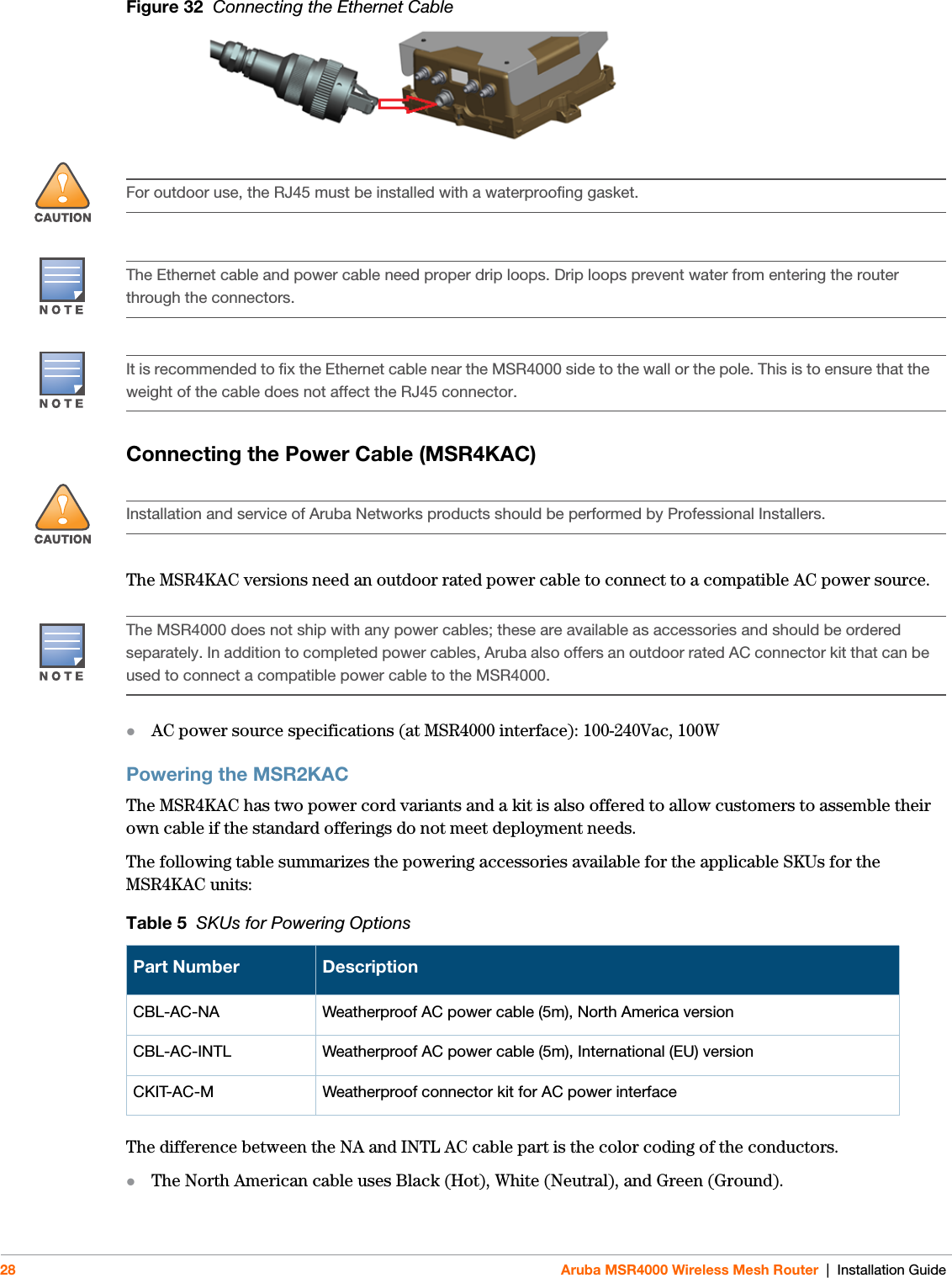
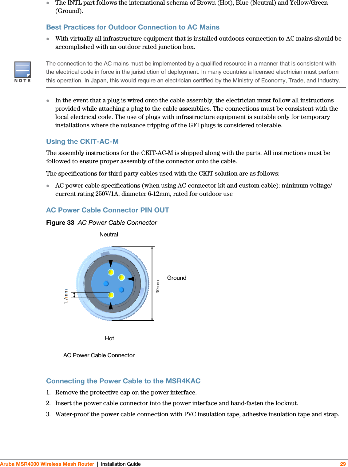
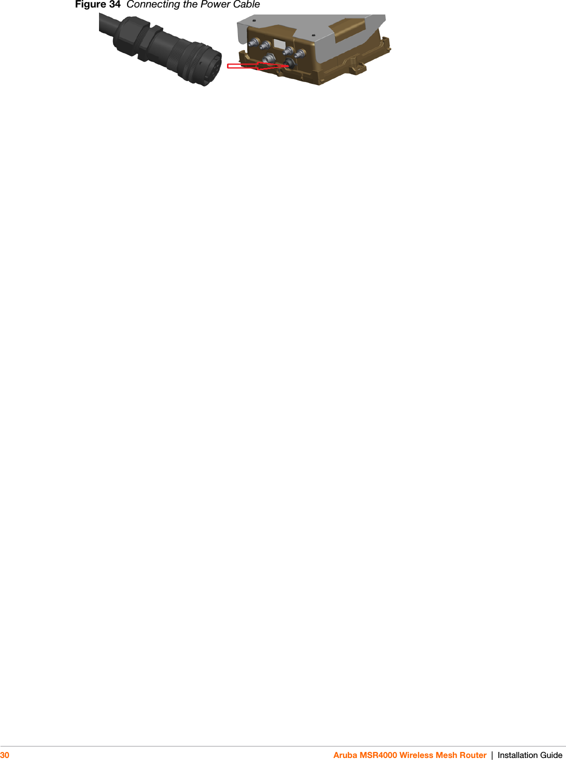
- 1. Installation Guide
- 2. ProfInstall-Instruction
- 3. Revised Installation Guide
- 4. updated Installation Guide
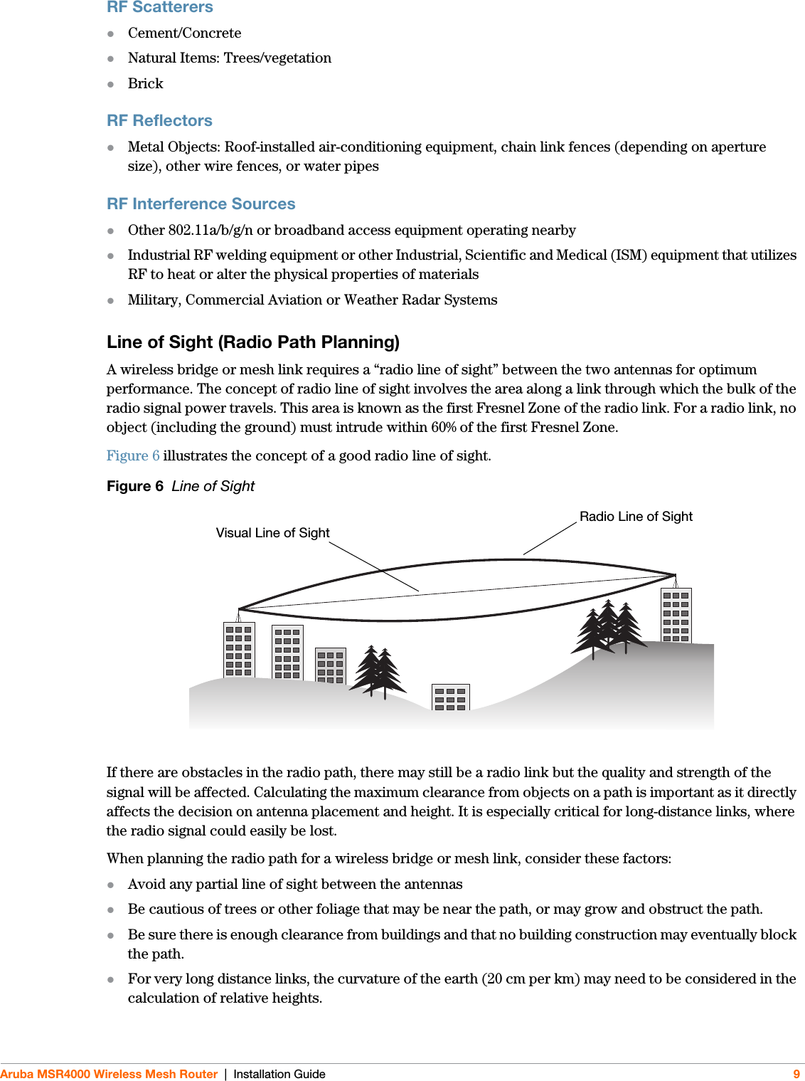
updated Installation Guide