Hewlett Packard Enterprise RAP5WN Aruba RAP Multi-port Remote Access Point User Manual RAP 5WN IG
Aruba Networks, Inc. Aruba RAP Multi-port Remote Access Point RAP 5WN IG
Contents
manual
RAP-5WN Remote Access Point
Installation Guide
About the RAP-5WN
The Aruba RAP-5WN is part of a comprehensive remote network solution. This
device works in conjunction with other Aruba products, such as Aruba Mobility
Controllers, and provides the following capabilities:
zCan be deployed remotely as a Remote Access Point (RAP)
zProtocol-independent networking functionality
zIEEE 802.11 a/b/g/n operation as a wireless Access Point
zIEEE 802.11 a/b/g/n operation as a wireless Air Monitor
zCan be centrally managed, configured, and upgraded through an Aruba Mobility
Controller
zWireless Transceiver
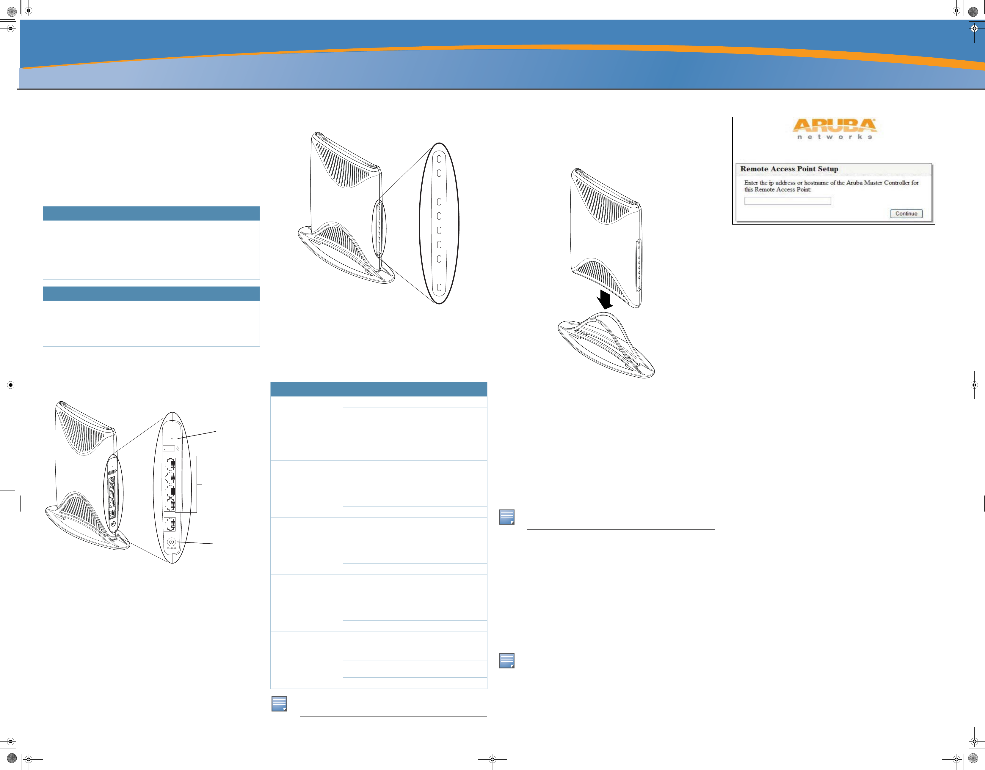
RAP-5WN Overview
Rear View
Figure 1 Rear View
10/100/1000Base-T Ethernet Port
The RAP-5WN has one 10/100/1000Base-T port used wired connectivity.
10/100Base-T Ethernet Ports
The RAP-5WN has four 10/100Base-T (RJ-45) ethernet ports for wired network
connectivity. These are ports 1 through 4.
DC IN (Power Socket)
The device is turned on when the attached power adapter (included) is plugged into
a power source (outlet). The device turns off by unplugging the device from the
power source.
USB Port
The purpose of this USB port is to support Cellular modems.
Reset Button
To reset the RAP-5WN, insert a small, narrow object, such as a pin or paperclip, into
the hole indicated in Figure 1 and press and hold the button while powering on the
RAP-5WN. This will return the device to factory default settings.
Front View
Figure 2 Front View
LEDs
The RAP-5WN has eight LED status indicators.
zPOWER: Indicates whether or not the RAP-5WN is powered on.
zGigabit Ethernet Port 0: Indicates activity and/or status on this port.
zFast Ethernet Ports 1-4: Indicates activity and/or status on these ports
z2.4 GHz Radio: Indicates status of the 2.4 GHz radio
z5 GHz Radio: Indicates status of the 5 GHz radio.
The Aruba AP Setup
Installation
The RAP-5WN is shipped with a stand to use on flat (i.e. table top) surfaces. Place
the RAP-5WN in the stand (see Figure 3) and place the stand on a flat, level surface.
Figure 3 Stand Installation
Connecting the Cables
You must connect the RAP-5WN to a network device that has access to the Internet,
such as a router or modem.
1. Connect one end of the provided RJ-45 cable to port 0 on the RAP-5WN.
2. Connect the other end of the RJ-45 cable to a free RJ-45 port on your modem or
router.
3. Attach the provided power adapter to the DC IN port on the RAP-5WN.
4. Connect the other end of the power adapter to a power outlet.
The POWER LED is lit (solid green) when the RAP-5WN is receiving power.
Verifying Successful Installation
Once the RAP-5WN’s PWR LED has come up and the boot cycle is complete, you
can connect to your company or corporate network.
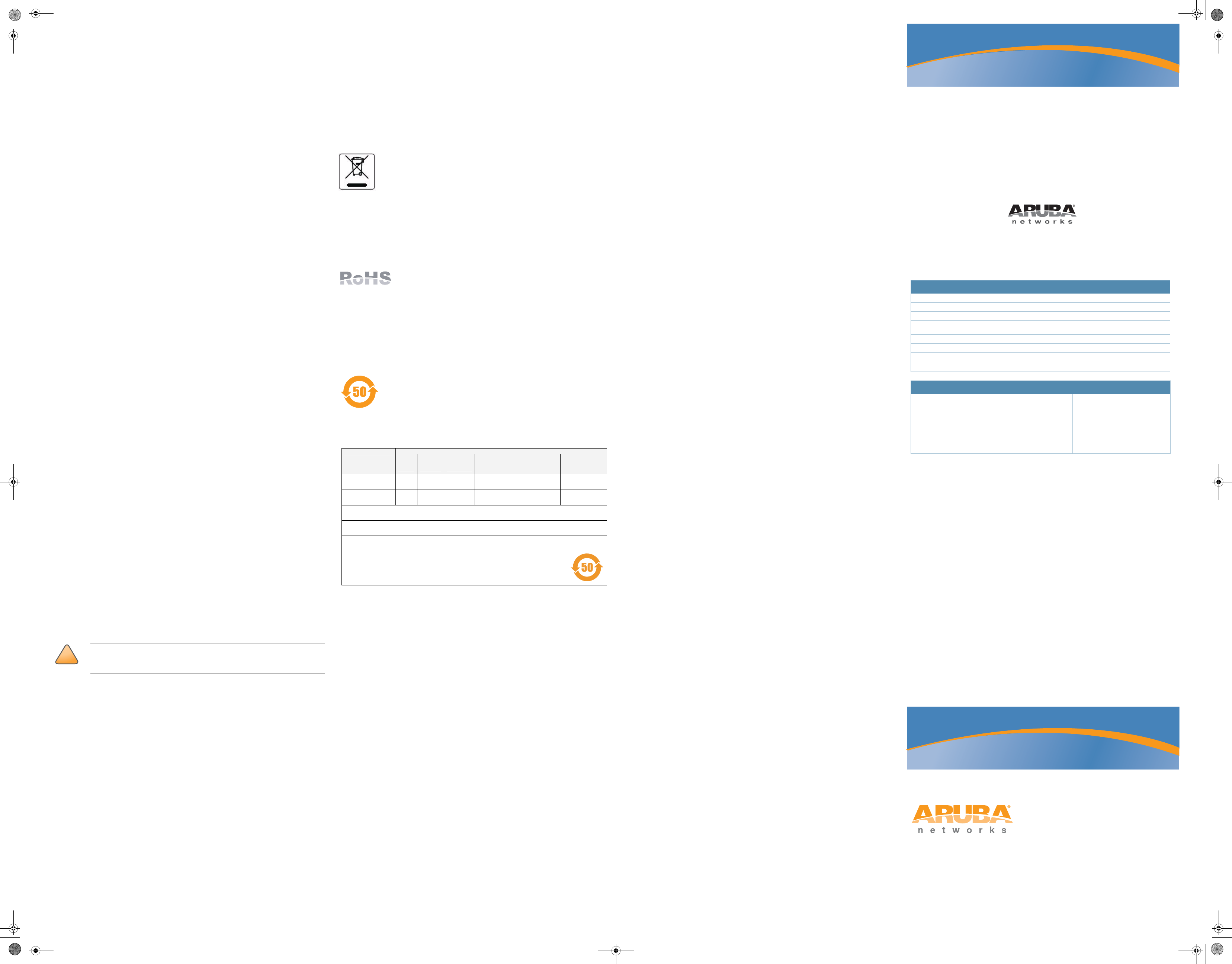
Provisioning at Home
If your IT administrator instructed you to provision your RAP-5WN, complete the
following steps after the RAP-5WN has been powered.
1. Connect one end of a second RJ-45 cable to port 1 on the RAP-5WN and the
other end to your computer.
2. Open a web browser and navigate to any URL.
3. An Aruba web page will appear (see Figure 4), requesting the IP address of the
master controller. Enter the IP address provided to you by your IT
administrator.
The RAP-5WN will connect to the designated master controller and download the
necessary provisioning information. When the RAP-5WN comes back up, it is ready
to use.
Figure 4 Manual Provisioning Page
Specifications
Mechanical
Device Dimensions (HxWxD):
z177.8mm x 31.75mm x 241.3mm
z7" x 1.25‘” x 9.5"
Device Weight:
z1 lb. / 453.6 grams
Shipping Dimensions (HxWxD):
z92mm x 300mm x 280mm
z3.6" x 11.8" x 11"
Temperature:
zOperating: 0ºC to 40ºC (32ºF to 104ºF)
zStorage: -10ºC to 70ºC (14ºF to 158ºF)
Relative Humidity:
z5% to 95% non-condensing
Mounting:
zStand for a flat level surface (i.e. table top)
Antenna:
zIntegrated, non-detachable articulating tri-band antenna
Visual Status Indicators (LEDs):
zPOWER: Power / Status
z0: 10/100/1000Base-T Ethernet Port
z1 - 4: 10/100Base-T Ethernet Port
z5 GHz
z2.4 GHz
Electrical
Ethernet:
z1 x 100/1000Base-T auto-sensing Ethernet RJ-45 Interface, MDI/MDX
z4x 10/100 Base-T auto-sensing Ethernet RJ-45 Interface, MDI/MDX
zIEEE 802.3, IEEE 802.3u, IEEE 802.3ab
Wireless LAN
Network Standards:
zIEEE 802.11a, IEEE 802.11b, IEEE 802.11g, and IEEE 802.11n
Antenna Type:
zIntegral, dual, omni-directional multi-band dipole (supports up to 3x3 MIMO
with spatial diversity)
Antenna Gain:
z3.5 dBi at 2.4 GHz
z5 dBi at 5 GHz
Radio Technology:
zOrthogonal Frequency Division Multiplexing (OFDM)
zDirect Sequence Spread Spectrum (DSSS)
Package Contents
z1 x RAP-5WN Remote Access Point
z1 x Installation Guide (this document)
z1 x RJ-45 Ethernet Cable
z1 x Power Adapter (12V 1.25A)
z1 x Stand
Inform your supplier if there are any incorrect, missing or damaged parts. If possible,
retain the carton, including the original packing materials. Use them to repack the product
in case there is a need to return it.
Before You Begin
Before installing your RAP-5WN Remote Wireless Access Point, please ensure you
have the following:
z1 x RJ-45 Ethernet Cable
z1 x Power Adapter
z1 x RAP-5WN
z1 x Stand
Power
0
1
2
3
4
Reset
Power
Socket
Reset
Button
USB
Port
10/100/1000Base-T
Gigabit Ethernet Port
10/100Base-T
Fast Ethernet Port
LED Color(s) Activity Action
POWER Green,
Red
Off No Power
On
(Green)
Power on, device ready
Flashing
(Green)
Device booting, not ready
On
(Red)
Device is not booting.
Port 0 (WAN) Green,
Amber
Off No link
On
(Amber)
Link established at 10/100 Mbps
On
(Green)
Link established at 1000 Mbps
Flashing Ethernet link activity
Ports 1 - 4 (LAN) Green,
Amber
Off No link
On
(Amber)
Link established at 10 Mbps
On
(Green)
Link established at 100 Mbps
Flashing Ethernet link activity
2.4 GHz Green,
Amber
Off 2.4 GHz radio disabled
On
(Amber)
2.4 GHz radio enabled in 802.11b/g mode
On
(Green)
2.4 GHz radio enabled in 802.11n mode
Flashing 2.4 GHz air monitor
5 GHz Green,
Amber
Off 5 GHz radio disabled
On
(Amber)
5 GHz radio enabled in 802.11a mode
On
(Green)
5 GHz radio enabled in 802.11n mode
Flashing 5 GHz air monitor
NOTE
If the POWER LED remains RED for more than 10 seconds, please attempt to
power cycle the device. If the LED remains RED, contact you IT administrator.
Power
0
1
2
3
4
2.4GHz
5GHz
NOTE
See the Provisioning at Home section if you are unable to connect
successfully.
NOTE
Contact your IT administrator if you are still unable to connect successfully.
RAP-5WN_IG.fm Page 1 Tuesday, December 23, 2008 1:30 PM
RAP-5WN Remote Access
Point
Installation Guide
www.arubanetworks.com
1344 Crossman Avenue
Sunnyvale, California 94089
Phone: 408.227.4500
Fax 408.227.4550
RAP-5WN Remote Access Point | Installation Guide
Part Number 0510580-01 | December 2008
Contacting Aruba Networks
Web Site Support
Main Site http://www.arubanetworks.com
Support Site https://support.arubanetworks.com
Software Licensing Site https://licensing.arubanetworks.com/login.php
Wireless Security Incident
Response Team (WSIRT)
http://www.arubanetworks.com/support/wsirt.php
Americas and APAC Support Email support@arubanetworks.com
EMEA Support Email emea.support@arubanetworks.com
WSIRT Email
Please email details of any security
problem found in an Aruba product.
wsirt@arubanetworks.com
Telephone Support
Aruba Corporate +1 (408) 227-4500
FAX +1 (408) 227-4550
Support
United States
Universal Free Phone Service Number (UIFN): Australia, Canada,
China, France, Germany, Hong Kong, Ireland, Israel, Japan, Korea,
Singapore, South Africa, Taiwan, and the UK
All Other Countries
800-WI-FI-LAN (800-943-4526)
+800-4WIFI-LAN (+800-49434-526)
+1 (408) 754-1200
Copyright
© 2008 Aruba Networks, Inc. AirWave®, Aruba Networks®, Aruba Mobility Management System®, Bluescanner,
For Wireless That Works®, Mobile Edge Architecture, People Move. Networks Must Follow., RFProtect, The All
Wireless Workplace Is Now Open For Business, and The Mobile Edge Company® are trademarks of Aruba
Networks, Inc. All rights reserved. All other trademarks are the property of their respective owners.
Open Source Code
Certain Aruba products include Open Source software code developed by third parties, including software code
subject to the GNU General Public License ("GPL"), GNU Lesser General Public License ("LGPL"), or other Open
Source Licenses. The Open Source code used can be found at this site:
http://www.arubanetworks.com/open_source
Legal Notice
The use of Aruba Networks, Inc. switching platforms and software, by all individuals or corporations, to terminate
other vendors' VPN client devices constitutes complete acceptance of liability by that individual or corporation
for this action and indemnifies, in full, Aruba Networks, Inc. from any and all legal actions that might be taken
against it with respect to infringement of copyright on behalf of those vendors.
Warranty
This hardware product is protected by the standard Aruba warranty of one year parts/labor. For more
information, refer to the ARUBACARE SERVICE AND SUPPORT TERMS AND CONDITIONS.
Altering this device (such as painting it) voids the warranty.
Radio Modulation Type:
z802.11a - CCK, BPSK, QPSK, 16-QAM, 64-QAM
z802.11b - CCK, BPSK, QPSK
z802.11g - CCK, BPSK, QPSK, OFDM
z802.11n draft 2.0
Media Access Control:
zCSMA/CA with ACK
Supported Frequency Bands 2.4 GHz:
z2.400 ~ 2.4835 GHz (Global), channels country specific
Support Frequency Bands 5 GHz
z5.150 ~ 5.250 GHz (low band), country-specific
z5.250 ~ 5.350 GHz (mid band), country-specific
z5.470 ~ 5.725 GHz (Worldwide), country-specific
z5.725 ~ 5.825 GHz (high band), country-specific
Supported Countries:
zComplete country list available at http://www.arubanetworks.com/products/aps/
certification
Data Rates:
z802.11b - 1, 2, 5.5, 11 Mbps per channel
z802.11g - 6, 9, 12, 18, 24, 36, 48 and 54 Mbps per channel
z802.11a - 6, 9, 12, 18, 24, 36, 48 and 54 Mbps per channel
z802.11n - Data rate MCS0 – MCS15 (from 6.5 Mbps to 300 Mbps)
Output Transmit Power:
z802.11a: 17 dBm at 6 Mbps; 15 dBm at 54 Mbps
z802.11b: 18 dBm
z802.11g: 17 dBm at 6Mbps; 15 dBm at 54 Mbps
z802.11n: 19 dBm at MCS0; 11 dBm at MCS15
Miscellaneous Functionality
Maximum Clients:
z255 concurrent client sessions
Radio Band Selection:
zVia Mobility Controller in software
Manageability:
zManagement of all 802.11 parameters
zNetwork Wide AP Management via CLI, WEB GUI and SNMPv3
zAccess Point Profiles, managed by Geographical Location, BSSID and Radio
Type
Encryption (AP and Mobility Controller):
z40bit / 64bit / 128bit / 152bit WEP, TKIP, AES
Compliance
Aruba provides a multi-language document containing country-specific restrictions
and additional safety and regulatory information for all Aruba hardware products.
You can read or download this document, on our website at www.arubanetworks.com/
safety_addendum.
Certifications
Electromagnetic Compatibility
zFCC DOC Part 15 Class B (digital portion)
zFCC Part 15 Subpart C 15.247
zFCC Part 15 Subpart E 15.407
zICES-003 Class B (Canada)
zRSS 210 (Canada)
zVCCI Class B (Japan)
zTelec ARIB STD-T66
zCE marked with NB letter of opinion (ETS 300 328 2.4 GHz, ETS 301 893 5GHz,
EN 300 382-2, EN 301 489-1/489-17)
zR&TTE Directive
zMIC (Korea)
zSRRC (China)
zAS/NZS CISPR22: 2002 Class B
zAS/NZS 4268
zDGT (Taiwan)
Safety Compliance
zcULus Listed 60950
zIEC 60950
zEN 60950
zPSE Mark (Japan)
Disposal of the RAP-5WN
For the most current information about Global Environmental Compliance and
Aruba products, see our website at www.arubanetworks.com/safety_addendum.
This product at end of life is subject to separate collection and
treatment in the EU Member States, Norway, and Switzerland, and
therefore is marked with the symbol shown at the left (crossed out
wheelie bin). The treatment applied at end of life of these products in
these countries shall comply with the applicable national laws
implementing Directive 2002/96EC on Waste of Electrical and Electronic Equipment
(WEEE).
The WEEE Directive 2002/96/EC and RoHS (Restriction of Hazardous Substances)
Directive 2002/95/EC sets collection, recycling and recovery targets for various
categories of electrical products and their waste.
European Union RoHS
The Restriction on Hazardous Substances Directive (RoHS)
(2002/95/EC), which accompanies the WEEE Directive, bans the
use of heavy metals and brominated flame-retardants in the
manufacture of electrical and electronic equipment. Specifically, restricted
materials under the RoHS Directive are Lead (Including Solder used in PCB’s),
Cadmium, Mercury, Hexavalent Chromium, and Bromine.
Aruba declares compliance with the European Union (EU) WEEE Directive (2002/
96/EC). For more information on WEEE, refer to:
http://www.dti.gov.uk/sustainability/weee
China RoHS
Aruba products comply with China environmental declaration
requirements and are labeled with the “EFUP 50” label shown at the
left.
Warranty
Standard warranty - 1 year return to manufacturer
!
CAUTION
Aruba Access Points must be installed by a professional installer. The
professional installer is responsible for ensuring that grounding is available and
that it meets applicable local and national electrical codes.
Ქኂ‛ ჿ䋼
Hazardous Materials Declaration
Ქኂ‛䋼ᚗర⚛Hazardous Substances)
ㇱઙฬ⒓
(Parts)
䪙
Lead
(Pb)
ᳮ
Mercury
(Hg)
䬝
Cadmium
(Cd)
ચ䫀
Chromium VI
Compounds
(Cr6+)
ᄙ⒈ 㘨 ⧶
Polybrominated
Biphenyls
(PBB)
ᄙ⒈ੑ䝮
⧶
Polybrominated
Diphenyl Ether
(PBDE)
⬉〝᧼
PCA Board X O O O O O
᪾㒘ઙ
Mechanical
Subassembly
X O O O O O
O:␜䆹Ქኂ‛䋼䆹ㇱઙᚲဋ䋼᧚ᢱਛ⊛㊂ဋSJ/T11363-2006ᷛಎ㾘ቯ⊛㒢㊂ⷐ᳞એਅޕ
This component does not contain this hazardous substance above the maximum concentration values in homogeneous materials
specified in the SJ/T11363-2006 Industry Standard.
X: ␜䆹Ქኂ‛䋼⥋ዋ䆹ㇱઙ⊛ᨱ৻ဋ䋼᧚ᢱਛ⊛㊂SJ/T11363-2006ᷛಎ㾘ቯ⊛㒢㊂ⷐ᳞ޕ
This component does contain this hazardous substance above the maximum concentration values in homogeneous materials specified
in the SJ/T11363-2006 Industry Standard.
ᇍ䫔ଂП᮹ⱘ᠔ଂѻકᴀ㸼ᰒ⼎կᑨ䫒ⱘ⬉ᄤֵᙃѻકৃ㛑ࣙ䖭ѯ⠽䋼ޕ
This table shows where these substances may be found in the supply chain of electronic information products, as of the date of sale of
the enclosed product.
ℸᷛᖫЎ䩜ᇍ᠔⍝ঞѻકⱘ⦃ֱՓ⫼ᳳᷛᖫ
ᶤѯ䳊䚼ӊӮ᳝ϔϾϡৠⱘ⦃ֱՓ⫼ᳳ՟བ⬉∴ऩܗഫ䌈݊ѻકϞ
ℸ⦃ֱՓ⫼ᳳ䰤া䗖⫼ѢѻકᰃѻકݠЁ᠔㾘ᅮⱘᴵӊϟᎹ
The Environment- Friendly Use Period (EFUP) for all enclosed products and their parts are per the
symbol shown here. The Environment- Friendly Use Period is valid only when the product is operated
under the conditions defined in the product manual.
Part Number: 0510303-01
RAP-5WN_IG.fm Page 2 Tuesday, December 23, 2008 1:30 PM

Regulatory Approvals
FCC Statement
This equipment has been tested and found to comply with the limits for a Class B digital
device, pursuant to Part 15 of the FCC Rules. These limits are designed to provide reasonable
protection against harmful interference in a residential installation.
This equipment generates, uses and can radiate radio frequency energy and, if not installed and
used in accordance with the instructions, may cause harmful interference to radio communica-
tions. However, there is no guarantee that interference will not occur in a particular installation.
If this equipment does cause harmful interference to radio or television reception, which can be
determined by turning the equipment off and on, the user is encouraged to try to correct the
interference by one of the following measures:
Reorient or relocate the receiving antenna.
Increase the separation between the equipment and receiver.
Connect the equipment into an outlet on a circuit different from that to which the receiver
is connected.
Consult the dealer or an experienced radio/TV technician for help.
To assure continued compliance, any changes or modifications not expressly approved by the
party responsible for compliance could void the user's authority to operate this equipment.
(Example - use only shielded interface cables when connecting to computer or peripheral
devices).
FCC Radiation Exposure Statement
This equipment complies with FCC RF radiation exposure limits set forth for an uncontrolled
environment. This equipment should be installed and operated with a minimum distance of 20
centimeters between the radiator and your body.
This device complies with Part 15 of the FCC Rules. Operation is subject to the following two
conditions:
(1) This device may not cause harmful interference, and
(2) This device must accept any interference received, including interference that may cause
undesired operation.
This transmitter must not be co-located or operating in conjunction with any other antenna or
transmitter.
The antennas used for this transmitter must be installed to provide a separation distance of at
least 20 cm from all persons and must not be co-located or operating in conjunction with any
other antenna or transmitter.
Channel
The Wireless Channel sets the radio frequency used for communication.
•Access Points use a fixed Channel. You can select the Channel used. This allows you to
choose a Channel which provides the least interference and best performance. In the USA
and Canada, 11 channel are available. If using multiple Access Points, it is better if adjacent
Access Points use different Channels to reduce interference.
• In "Infrastructure" mode, Wireless Stations normally scan all Channels, looking for an
Access Point. If more than one Access Point can be used, the one with the strongest
signal is used. (This can only happen within an ESS.)
• If using "Ad-hoc" mode (no Access Point), all Wireless stations should be set to use the
same Channel. However, most Wireless stations will still scan all Channels to see if there
is an existing "Ad-hoc" group they can join.
Note:This equipment marketed in USA is restricted by firmware to only operate on 2.4G channel 1-11
.