Hewlett Packard Enterprise WA3620I Wireless LAN access Point User Manual WA3610i GN 20120210
Hewlett-Packard Company Wireless LAN access Point WA3610i GN 20120210
UserManual.wiki
>
Hewlett Packard Enterprise
>
WA3620I User Manual
(WA3610i-GN) User manual_20120210
Navigation menu
Upload a User Manual
Namespaces
Wiki Guide
HTML
PDF
Info
Views
User Manual
Discussion / Help
Navigation
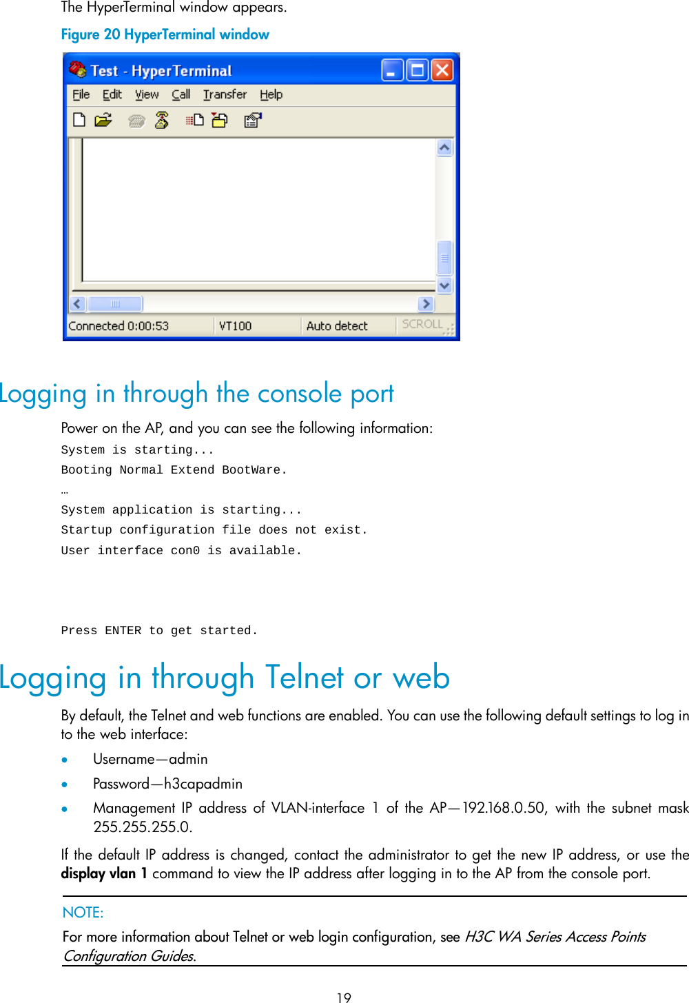
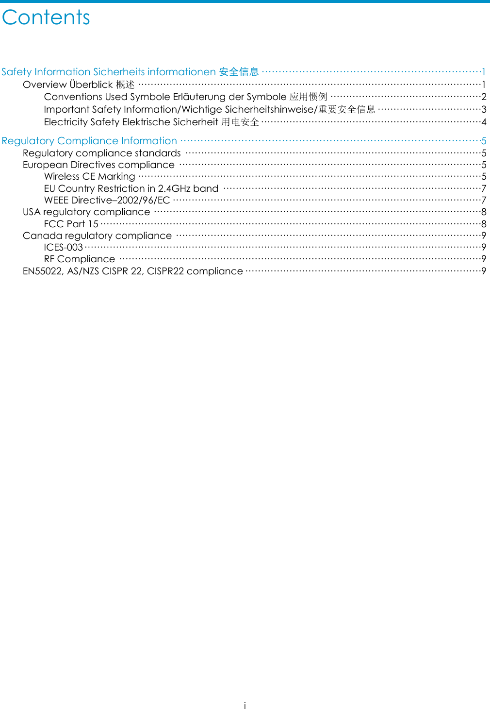
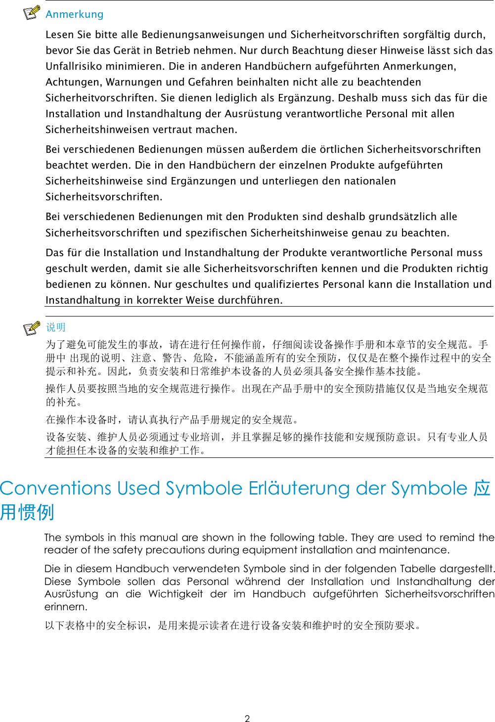
![Obtaining documentation You can access the most up-to-date H3C product documentation on the World Wide Web at http://www.h3c.com. Click the links on the top navigation bar to obtain different categories of product documentation: [Technical Support & Documents > Technical Documents] – Provides hardware installation, software upgrading, and software feature configuration and maintenance documentation. [Products & Solutions] – Provides information about products and technologies, as well as solutions. [Technical Support & Documents > Software Download] – Provides the documentation released with the software version. Technical support customer_service@h3c.com http://www.h3c.com Documentation feedback You can e-mail your comments about product documentation to info@h3c.com. We appreciate your comments.](https://usermanual.wiki/Hewlett-Packard-Enterprise/WA3620I/User-Guide-1675582-Page-4.png)
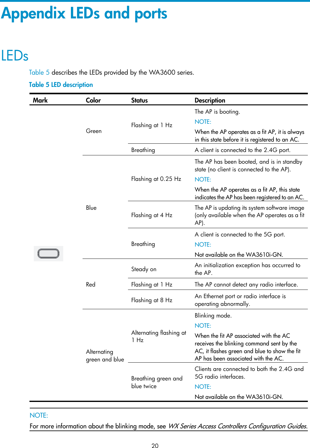
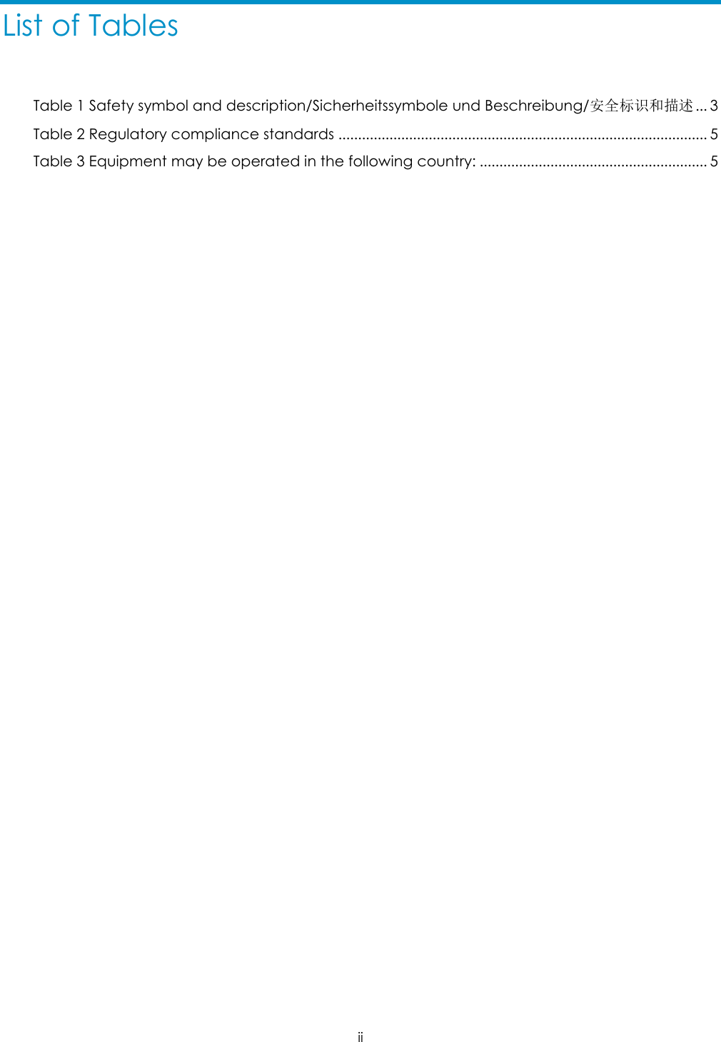
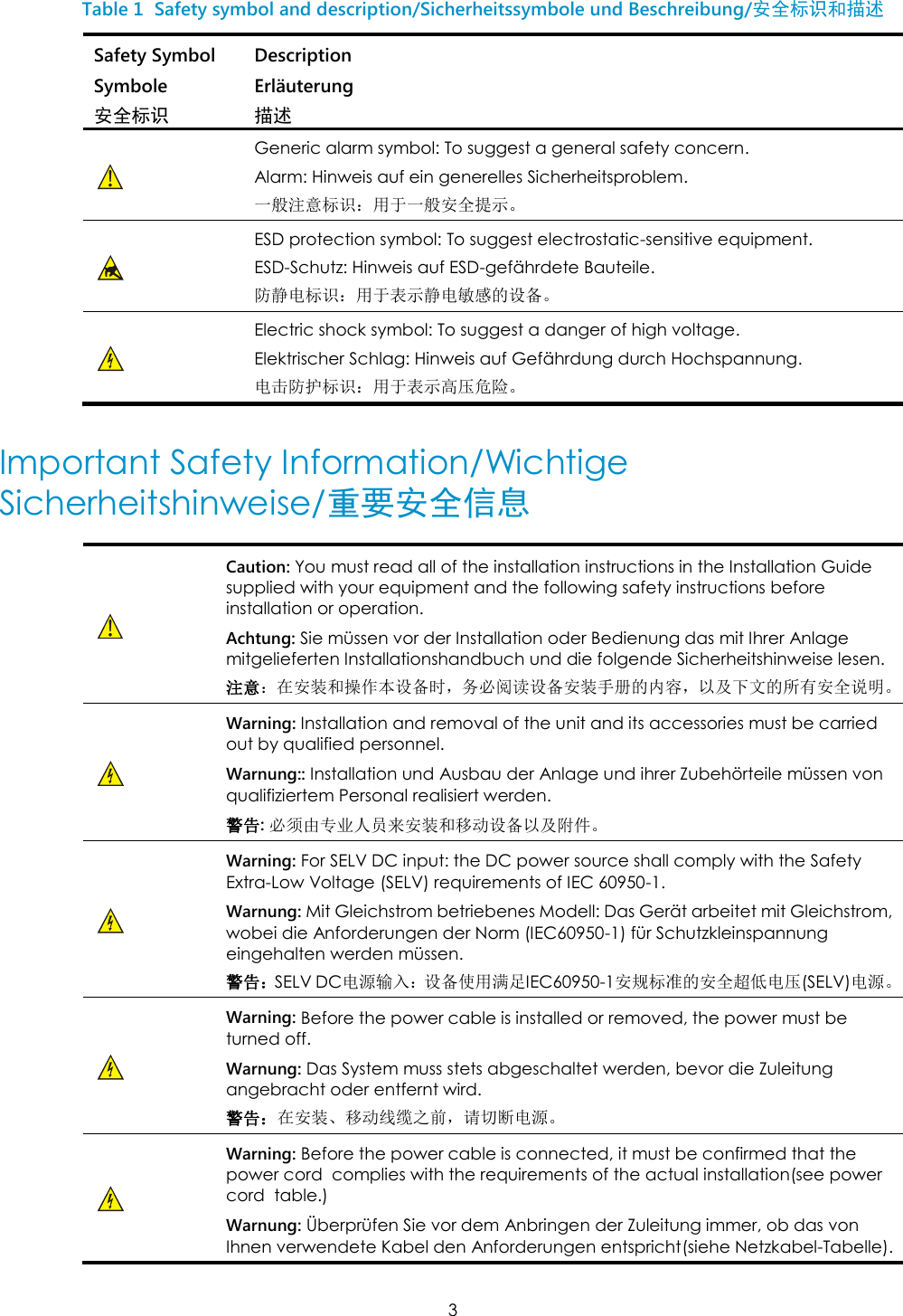
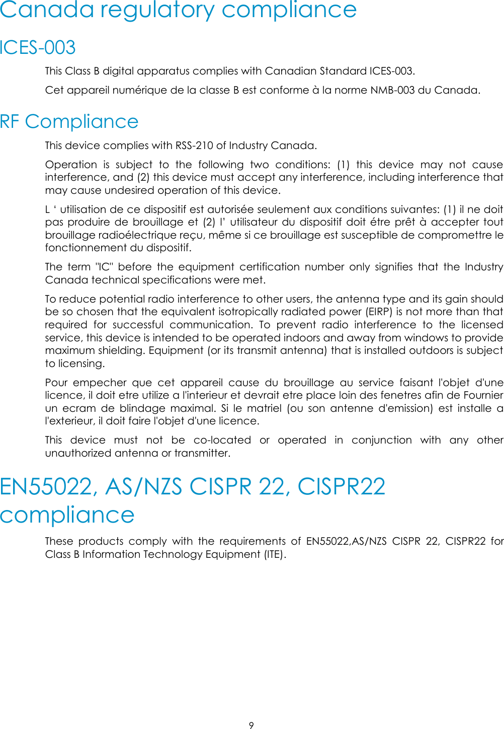
![6 AT BE CY CZ DK EE FI FR DE GR HU IE IT LV LT LU MT NL PL PT SK SI ES SE GB IS LI NO CH BG RO TR 1. Select the country in which the product is installed to ensure product operation is in compliance with local regulations. For information on how to select the country, refer to the “H3C A-Series Access Controllers WLAN Command Reference”. 2. Intended use: IEEE 802.11 b/g/n radio LAN device. 3. This product must maintain a minimum body to antenna distance of 20cm.Under these conditions this product will meet the Basic Restriction limits of 1999/519/EC(Council Recommendation of 12 July 1999 on the limitation of exposure of the general public to electromagnetic fields(0Hz-300GHz)). R&TTE declaration statements: Česky [Czech] H3C Company tímto prohlašuje, že tento Zařízení je ve shodě se základními požadavky a dalšími příslušnými ustanoveními směrnice 1999/5/ES. Dansk [Danish] Undertegnede H3C Company erklærer herved, at følgende udstyr zařízení overholder de væ sentlige krav og øvrige relevante krav i direktiv 1999/5/EF. Deutsch [German] Hiermit erklärt H3C Company, dass sich das Gerät Ausrüstung in Übereinstimmung mit den grundlegenden Anforderungen und den übrigen einschlägigen Bestimmungen der Richtlinie 1999/5/EG befindet. Eesti [Estonian] Käesolevaga kinnitab H3C Company seadmed vastavust direktiivi 1999/5/EÜ põhinõuetele ja nimetatud direktiivist tulenevatele teistele asjakohastele sätetele. English Hereby, H3C Company, declares that this Equipment is in compliance with the essential requirements and other relevant provisions of Directive 1999/5/EC. Español [Spanish] Por medio de la presente H3C Company declara que el equipo cumple con los requisitos esenciales y cualesquiera otras disposiciones aplicables o exigibles de la Directiva 1999/5/CE. Ελληνική [Greek] ΜΕ ΣΗΝ ΠΑΡΟΤΑ H3C Company ΔΗΛΩΝΕΙ ΟΣΙ εξοπλισμός ΤΜΜΟΡΥΩΝΕΣΑΙ ΠΡΟ ΣΙ ΟΤΙΩΔΕΙ ΑΠΑΙΣΗΕΙ ΚΑΙ ΣΙ ΛΟΙΠΕ ΦΕΣΙΚΕ ΔΙΑΣΑΞΕΙ ΣΗ ΟΔΗΓΙΑ 1999/5/ΕΚ. Français [French] Par la présente H3C Company déclare que l'appareil équipement est conforme aux exigences essentielles et aux autres dispositions pertinentes de la directive 1999/5/CE. Italiano [Italian] Con la presente H3C Company dichiara che questo attrezzatura è conforme ai requisiti essenziali ed alle altre disposizioni pertinenti stabilite dalla direttiva 1999/5/CE. Latviski [Latvian] Ar šo H3C Company deklarē, ka iekārta atbilst Direktīvas 1999/5/EK būtiskajām prasībām un citiem ar to saistītajiem noteikumiem. Lietuvių [Lithuanian] Šiuo H3C Company deklaruoja, kad šis įranga atitinka esminius reikalavimus ir kitas 1999/5/EB Direktyvos nuostatas. Nederlands [Dutch] Hierbij verklaart H3C Company dat het toestel uitrusting in overeenstemming is met de essentiële eisen en de andere relevante bepalingen van richtlijn 1999/5/EG. Malti [Maltese] Hawnhekk, H3C Company, jiddikjara li dan tagħmir jikkonforma mal-ħtiġijiet essenzjali u ma provvedimenti oħrajn relevanti li hemm fid-Dirrettiva 1999/5/EC. Magyar Alulírott, H3C Company nyilatkozom, hogy a aprīkojums megfelel a vonatkozó](https://usermanual.wiki/Hewlett-Packard-Enterprise/WA3620I/User-Guide-1675582-Page-37.png)
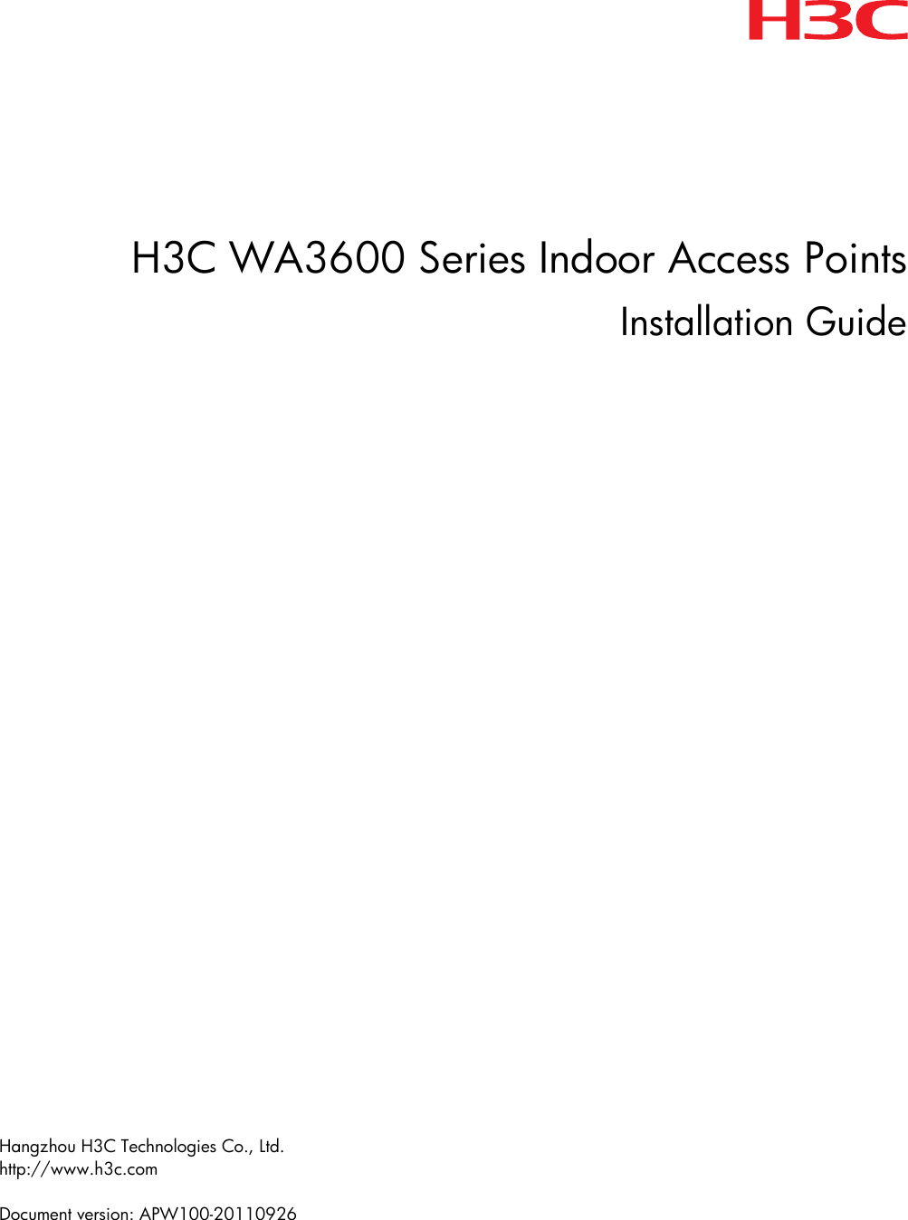
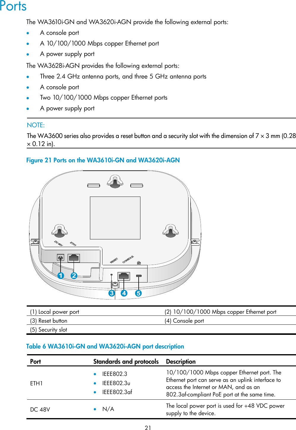
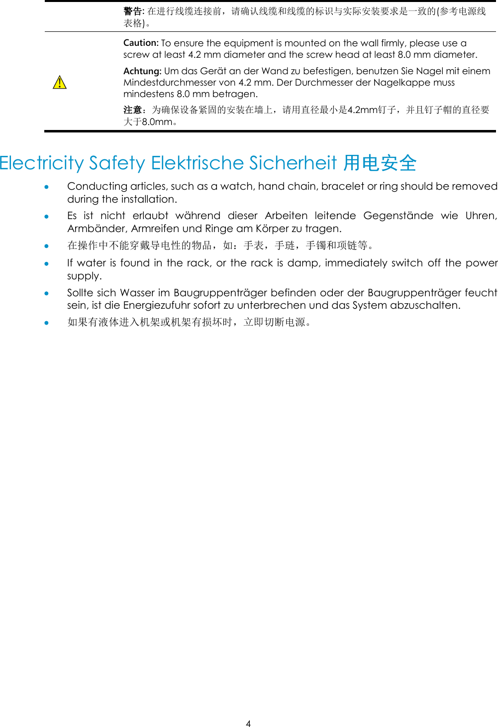
![7 [Hungarian] alapvetõ követelményeknek és az 1999/5/EC irányelv egyéb elõírásainak. Polski [Polish] Niniejszym H3C Company oświadcza, że urządzenie jest zgodny z zasadniczymi wymogami oraz pozostałymi stosownymi postanowieniami Dyrektywy 1999/5/EC. Português [Portuguese] H3C Company declara que este equipamento está conforme com os requisitos essenciais e outras disposições da Directiva 1999/5/CE. Slovensko [Slovenian] H3C Company izjavlja, da je ta oprema v skladu z bistvenimi zahtevami in ostalimi relevantnimi določili direktive 1999/5/ES. Slovensky [Slovak] H3C Company týmto vyhlasuje, že zariadenie spĺňa základné požiadavky a všetky príslušné ustanovenia Smernice 1999/5/ES. Suomi [Finnish] H3C Company vakuuttaa täten että laitteet tyyppinen laite on direktiivin 1999/5/EY oleellisten vaatimusten ja sitä koskevien direktiivin muiden ehtojen mukainen. Svenska [Swedish] Härmed intygar H3C Company att denna utrustning står I överensstämmelse med de väsentliga egenskapskrav och övriga relevanta bestämmelser som framgår av direktiv 1999/5/EG. Íslenska [Icelandic] Hér með lýsir H3C Company yfir því að búnaður er í samræ mi við grunnkröfur og aðrar kröfur, sem gerðar eru í tilskipun 1999/5/EC. Norsk [Norwegian] H3C Company erklæ rer herved at utstyret utstyr er i samsvar med de grunnleggende krav og øvrige relevante krav i direktiv 1999/5/EF. The most up to date copy of the signed EU Declaration of Conformity can be downloaded from: http://www.h3c.com/portal/Technical_Documents EU Country Restriction in 2.4GHz band These products may be used indoors or outdoors in all countries of the European Community using the 2.4GHz band: Channel 1-13, except where noted below. 1. In Belgium outdoor operation is only permitted using the 2.46-2.4835GHz band: Channel 13. 2. In France outdoor operation is only permitted using the 2.4-2.454GHz band: Channels 1-7. 3. In Italy the end-user must apply for a license from the national spectrum authority to operate this device outdoors. WEEE Directive–2002/96/EC The products this manual refers to are covered by the Waste Electrical & Electronic Equipment (WEEE) Directive and must be disposed of in a responsible manner.](https://usermanual.wiki/Hewlett-Packard-Enterprise/WA3620I/User-Guide-1675582-Page-38.png)