Hewlett Packard Enterprise WL548A 3Com AirProtect Sensor 5750 User Manual
Hewlett-Packard Company 3Com AirProtect Sensor 5750
UserManual.wiki
>
Hewlett Packard Enterprise
>
WL548A User Manual
User Manual
Navigation menu
Upload a User Manual
Namespaces
Wiki Guide
HTML
PDF
Info
Views
User Manual
Discussion / Help
Navigation
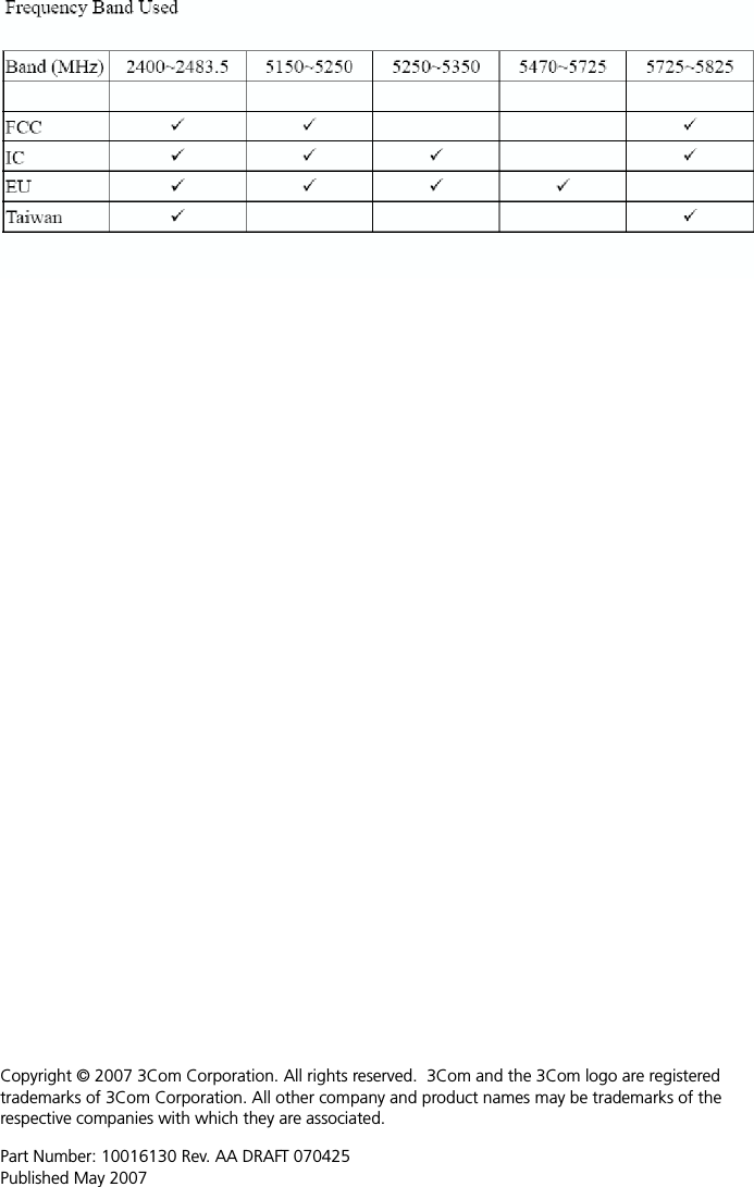
![9REGULATORY INFORMATIONThe 3Com AirProtect Sensor 5750, Model WL-548A (3CRWX5750GS) must be installed and used in strict accordance with the manufacturer’s instructions as described in the user documentation that comes with the product.This product contains encryption. It is unlawful to export out of the U.S. without obtaining a U.S. Export License. This product does not contain any user serviceable components. Any unauthorized product changes or modifications will invalidate 3Com’s warranty and all applicable regulatory certifications and approvals.This product must be installed by a professional technician/installer.Only antennas specified for your region by 3Com can be used with this product. The use of external amplifiers or non-3Com antennas may invalidate regulatory certifications and approvals.This product can only be used with the supplied antennas. CAUTION: EXPOSURE TO RADIO FREQUENCY RADIATIONThis device generates and radiates radio-frequency energy. In order to comply with FCC radio-frequency exposure guidelines for an uncontrolled environment, this equipment must be installed and operated while maintaining a minimum body to antenna distance of 20 cm (approximately 8 in.).The installer of this radio equipment must ensure that the antenna is located or pointed such that it does not emit RF field in excess of Health Canada limits for the general population; consult Safety Code 6, obtainable from Health Canada’s website www.hc-sc.gc.ca/rpb.This equipment complies with IC radiation exposure limits set forth for an uncontrolled environment. End users must follow the specific operating instructions for satisfying RF exposure compliance. This equipment should be installed and operated with minimum distance 20 cm between the radiator and your body.This product must maintain a minimum body to antenna distance of 20 cm. Under these conditions this product will meet the Basic Restriction limits of 1999/519/EC [Council Recommendation of 12 July 1999 on the limitation of exposure of the general public to electromagnetic fields (0 Hz to 300 GHz)].US — RADIO FREQUENCY REQUIREMENTSThis device must not be co-located or operated in conjunction with any other antenna or transmitter.This device is for indoor use only when using channels 36, 40, 44 or 48 in the 5.15 to 5.25 GHz frequency range.High power radars are allocated as primary users of the 5.25 to 5.35 GHz and 5.65 to 5.85 GHz bands. These radar stations can cause interference with and/or damage this device.FCC NOTICETo comply with FCC Part 15 rules in the United States, the system must be professionally installed to ensure compliance with the Part 15 certification. It is the responsibility of the operator and professional installer to ensure that only certified systems are deployed in the United States. The use of the system in any other combination (such as co-located antennas transmitting the same information) is expressly forbidden in accordance with FCC rules CFR47 Part 15.204.USA—FEDERAL COMMUNICATIONS COMMISSION (FCC) EMC COMPLIANCEThis equipment has been tested and found to comply with the limits for a Class B digital device, pursuant to Part 15 of the FCC Rules. These limits are designed to provide reasonable protection against harmful interference in a residential installation. This equipment generates, uses and can radiate radio frequency energy and, if not installed and used in accordance with the instructions, may cause harmful interference to radio communications. However, there is no guarantee that interference will not occur in a particular installation. If this equipment does cause harmful interference to radio or television reception, which can be determined by turning the equipment off and on, the user is encouraged to try to correct the interference by one or more of the following measures:• Reorient or relocate the receiving antenna.• Increase the separation between the equipment and receiver.• Connect the equipment into an outlet on a circuit different from that to which the receiver is connected.• Consult the dealer or an experienced radio/TV technician for help.i](https://usermanual.wiki/Hewlett-Packard-Enterprise/WL548A/User-Guide-789679-Page-10.png)
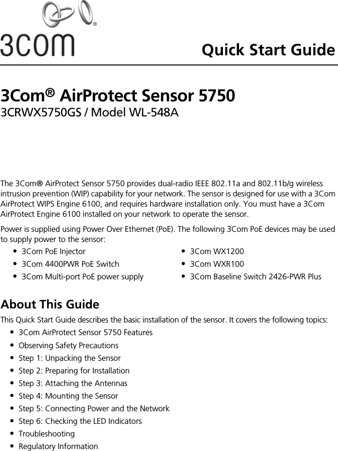
![11INDUSTRY CANADA - EMISSIONS COMPLIANCE STATEMENTThis Class B digital apparatus complies with Canadian ICES-003.Avis de Conformité à la Réglementation d'Industrie CanadaCet appareil numérique de la classe B est conform à la norme NMB-003 du Canada.SAFETY COMPLIANCE NOTICEThis device has been tested and certified according to the following safety standards and is intended for use only in Information Technology Equipment which has been tested to these or other equivalent standards:• UL Standard 60950-1• CAN/CSA C22.2 No. 60950-1• IEC 60950-1• EN 60950-1EU COMPLIANCE Intended use: IEEE 802.11a/b/g radio LAN deviceNOTE: To ensure product operation is in compliance with local regulations, select the country in which the product is installed. Česky [Czech] 3Com Coporation tímto prohlašuje, že tento RLAN device je ve shodě se základ-ními požadavky a dalšími příslušnými ustanoveními směrnice 1999/5/ES.Dansk [Danish] Undertegnede 3Com Corporation erklærer herved, at følgende udstyr RLAN device overholder de væsentlige krav og øvrige relevante krav i direktiv 1999/5/EF.Deutsch [German] Hiermit erklärt 3Com Corporation, dass sich das Gerät RLAN device in Überein-stimmung mit den grundlegenden Anforderungen und den übrigen einschlägigen Bestimmungen der Richtlinie 1999/5/EG befindet.Eesti [Estonian] Käesolevaga kinnitab 3Com Corporation seadme RLAN device vastavust direkti-ivi 1999/5/EÜ põhinõuetele ja nimetatud direktiivist tulenevatele teistele asjako-hastele sätetele.English Hereby, 3Com Corporation, declares that this RLAN device is in compliance with the essential requirements and other relevant provisions of Directive 1999/5/EC.Español [Spanish] Por medio de la presente 3Com Corporation declara que el RLAN device cum-ple con los requisitos esenciales y cualesquiera otras disposiciones aplicables o exigibles de la Directiva 1999/5/CE.Ελληνική [Greek] ΜΕ ΤΗΝ ΠΑΡΟΥΣΑ 3Com Corporation ΔΗΛΩΝΕΙ ΟΤΙ RLAN device ΣΥΜΜΟΡΦΩΝΕΤΑΙ ΠΡΟΣ ΤΙΣ ΟΥΣΙΩΔΕΙΣ ΑΠΑΙΤΗΣΕΙΣ ΚΑΙ ΤΙΣ ΛΟΙΠΕΣ ΣΧΕΤΙΚΕΣ ΔΙΑΤΑΞΕΙΣ ΤΗΣ ΟΔΗΓΙΑΣ 1999/5/ΕΚ.Français [French] Par la présente 3Com Corporation déclare que l'appareil RLAN device est con-forme aux exigences essentielles et aux autres dispositions pertinentes de la directive 1999/5/CE.Italiano [Italian] Con la presente 3Com Corporation dichiara che questo RLAN device è con-forme ai requisiti essenziali ed alle altre disposizioni pertinenti stabilite dalla direttiva 1999/5/CE.AT BE CY CZ DK EE FI FRDE GR HU IE IT LV LT LUMT NL PL PT SK SI ES SEGB IS LI NO CH BG RO TRThis equipment may be operated in](https://usermanual.wiki/Hewlett-Packard-Enterprise/WL548A/User-Guide-789679-Page-12.png)
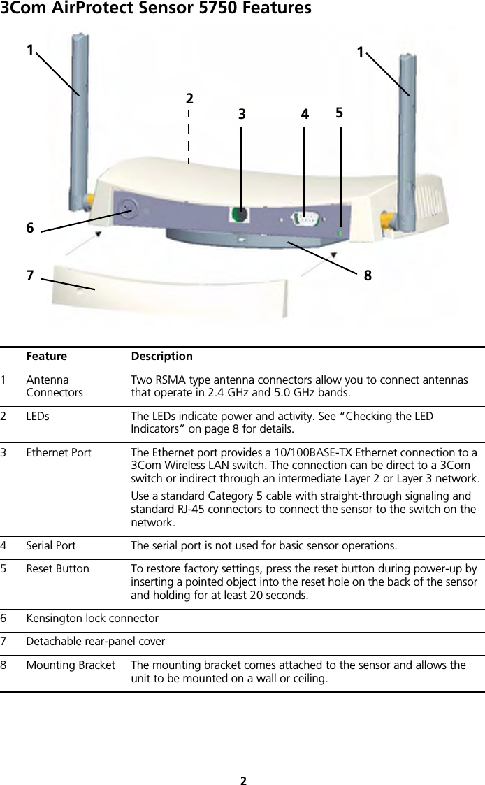
![12A copy of the signed Declaration of Conformity can be downloaded from the Product Support web page for the 3Com 3Com AirProtect Sensor 5750, Model WL-548A (3CRWX5750GS) at http://www.3Com.com. Also available at http://support.3com.com/doc/WL-548A_EU_DOC.pdfEU - RESTRICTIONS FOR USE IN THE 2.4 GHZ BANDThis device may be operated indoors or outdoors in all countries of the European Community using the 2.4 GHz band: Channels 1–13, except where noted below. •In Italy the end-user must apply for a license from the national spectrum authority to operate this device outdoors.•In Belgium outdoor operation is only permitted using the 2.46 – 2.4835 GHz band: Channel 13.•In France outdoor operation is only permitted using the 2.4 – 2.454 GHz band: Channels 1 – 7.EU - RESTRICTIONS FOR USE IN THE 5 GHZ BAND Latviski [Latvian] Ar šo 3Com Corporation deklarē, ka RLAN device atbilst Direktīvas 1999/5/EK būtiskajām prasībām un citiem ar to saistītajiem noteikumiem.Lietuvių [Lithuanian] Šiuo 3Com Corporation deklaruoja, kad šis RLAN device atitinka esminius reika-lavimus ir kitas 1999/5/EB Direktyvos nuostatas.Nederlands [Dutch] Hierbij verklaart 3Com Corporation dat het toestel RLAN device in overeenstem-ming is met de essentiële eisen en de andere relevante bepalingen van richtlijn 1999/5/EG.Malti [Maltese] Hawnhekk, 3Com Corporation, jiddikjara li dan RLAN device jikkonforma mal-htigijiet essenzjali u ma provvedimenti ohrajn relevanti li hemm fid-Dirrettiva 1999/5/EC.Magyar [Hungarian] Alulírott, 3Com Corporation nyilatkozom, hogy a RLAN device megfelel a vonat-kozó alapvetõ követelményeknek és az 1999/5/EC irányelv egyéb elõírásainak.Polski [Polish] Niniejszym 3Com Corporation oświadcza, że RLAN device jest zgodny z zasad-niczymi wymogami oraz pozostałymi stosownymi postanowieniami Dyrektywy 1999/5/EC.Português [Portuguese] 3Com Corporation declara que este RLAN device está conforme com os requisi-tos essenciais e outras disposições da Directiva 1999/5/CE.Slovensko [Slovenian] 3Com Corporation izjavlja, da je ta RLAN device v skladu z bistvenimi zahtevami in ostalimi relevantnimi določili direktive 1999/5/ES.Slovensky [Slovak] 3Com Corporation týmto vyhlasuje, že RLAN device spĺňa základné požiadavky a všetky príslušné ustanovenia Smernice 1999/5/ES.Suomi [Finnish] 3Com Corporation vakuuttaa täten että RLAN device tyyppinen laite on direkti-ivin 1999/5/EY oleellisten vaatimusten ja sitä koskevien direktiivin muiden ehtojen mukainen.Svenska [Swedish] Härmed intygar 3Com Corporation att denna RLAN device står I överensstäm-melse med de väsentliga egenskapskrav och övriga relevanta bestämmelser som framgår av direktiv 1999/5/EG.Íslenska [Icelandic] Hér með lýsir 3Com Corporation yfir því að RLAN device er í samræmi við grunnkröfur og aðrar kröfur, sem gerðar eru í tilskipun 1999/5/EC.Norsk [Norwegian] 3Com Corporation erklærer herved at utstyret RLAN device er i samsvar med de grunnleggende krav og øvrige relevante krav i direktiv 1999/5/EF.Allowed Frequency Bands Allowed Channel Numbers Countries5.15–5.35 & 5.470–5.725 GHz 36, 40, 44, 48, 52, 56, 60, 64, 100, 104, 108, 112, 116, 120, 124, 128, 132, 136, 140Austria, Belgium, Bulgaria, Cyprus, Czech Republic, Denmark, Estonia, Finland, France, Germany, Greece, Hungary, Iceland, Ireland, Italy, Latvia, Liechtenstein, Lithuania, Luxembourg, Malta, Netherlands, Norway, Poland, Portugal, Romania, Slovakia, Slovenia, Spain, Sweden, Switzerland, U.K.](https://usermanual.wiki/Hewlett-Packard-Enterprise/WL548A/User-Guide-789679-Page-13.png)