Hewlett Packard Enterprise WL565 11g 54Mbps Building to Building Bridge User Manual
Hewlett-Packard Company 11g 54Mbps Building to Building Bridge Users Manual
UserManual.wiki
>
Hewlett Packard Enterprise
>
WL565 User Manual
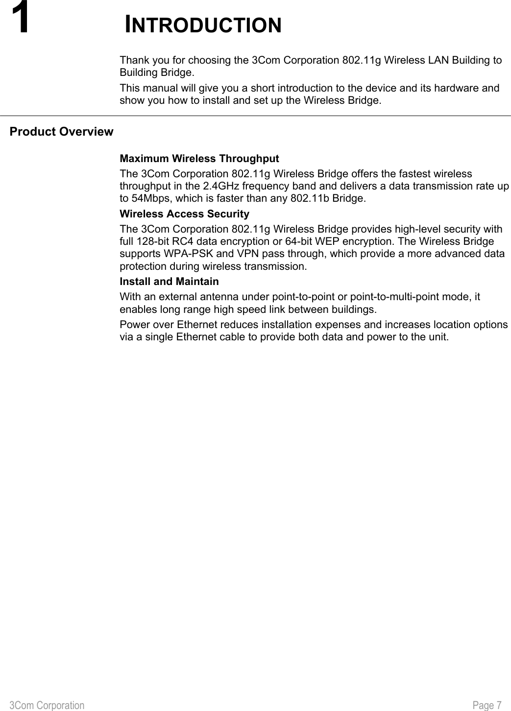
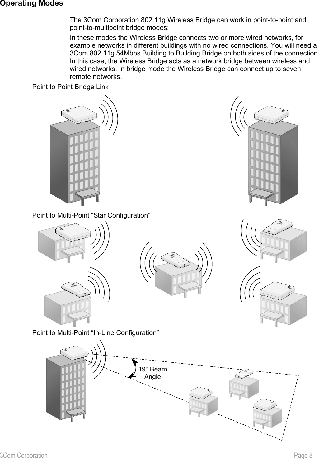
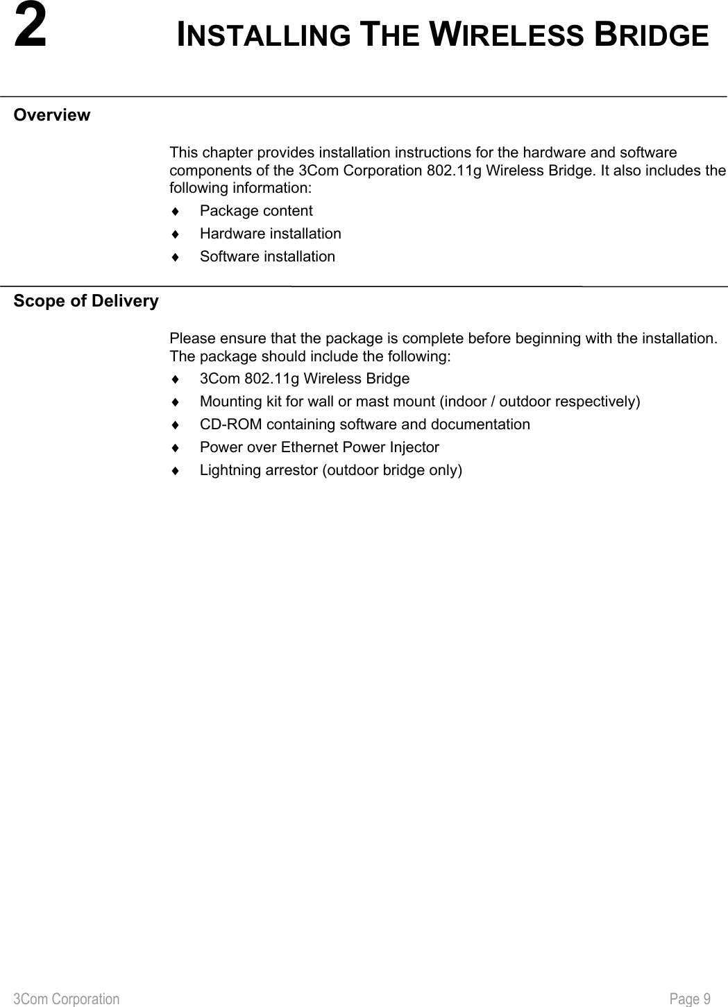
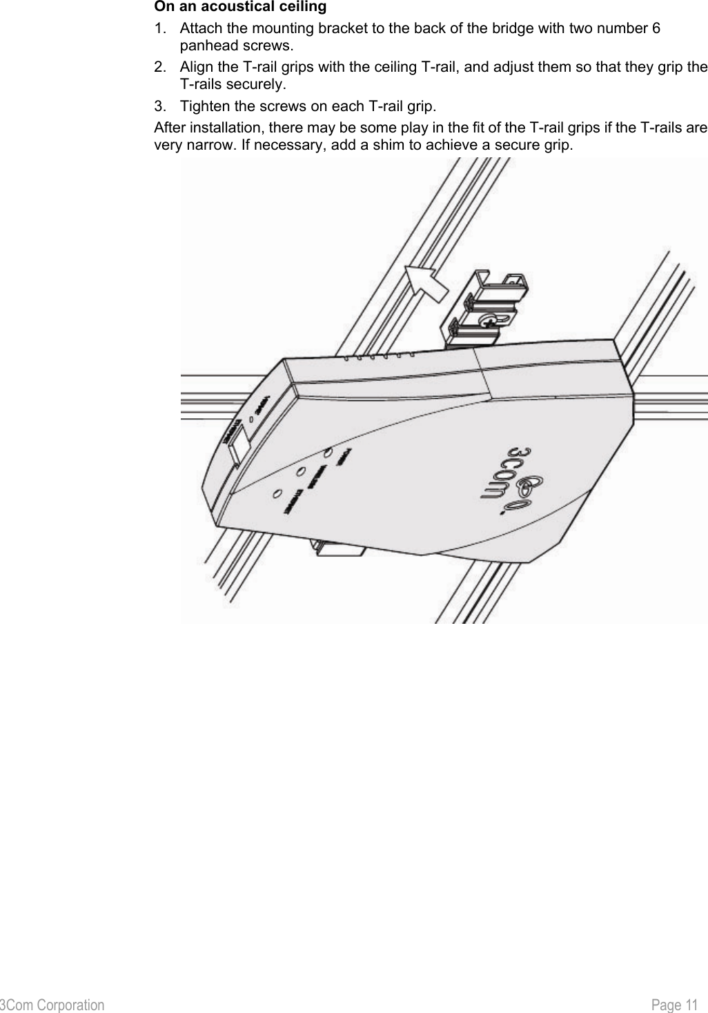
Users Manual
Navigation menu
Upload a User Manual
Namespaces
Wiki Guide
HTML
PDF
Info
Views
User Manual
Discussion / Help
Navigation
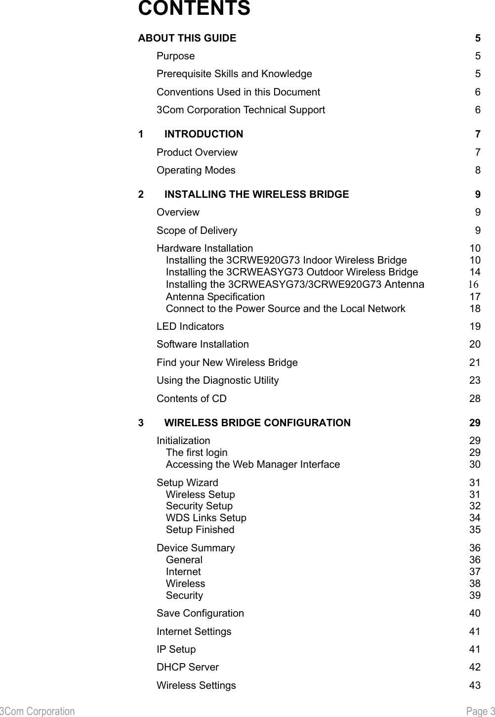


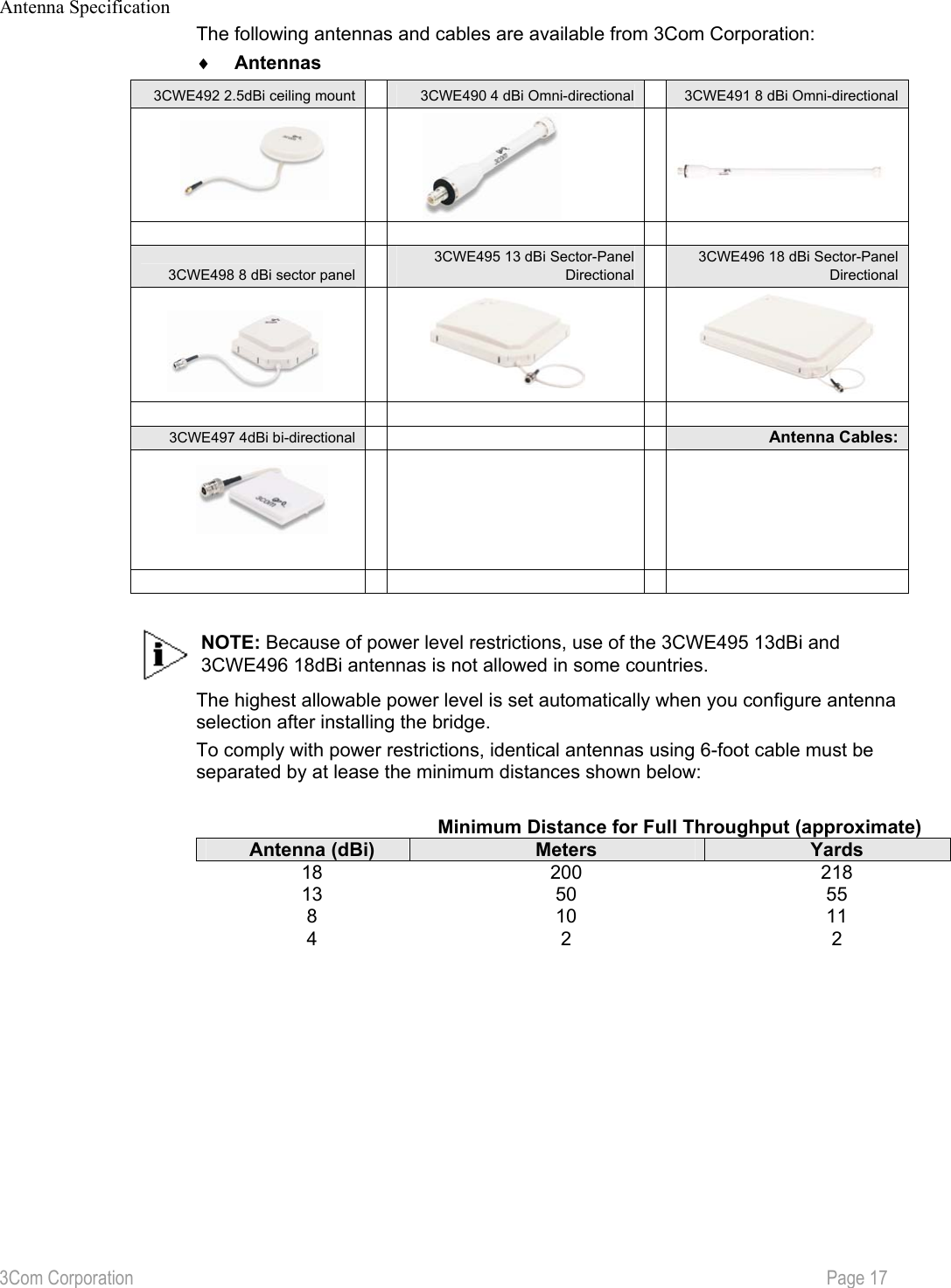
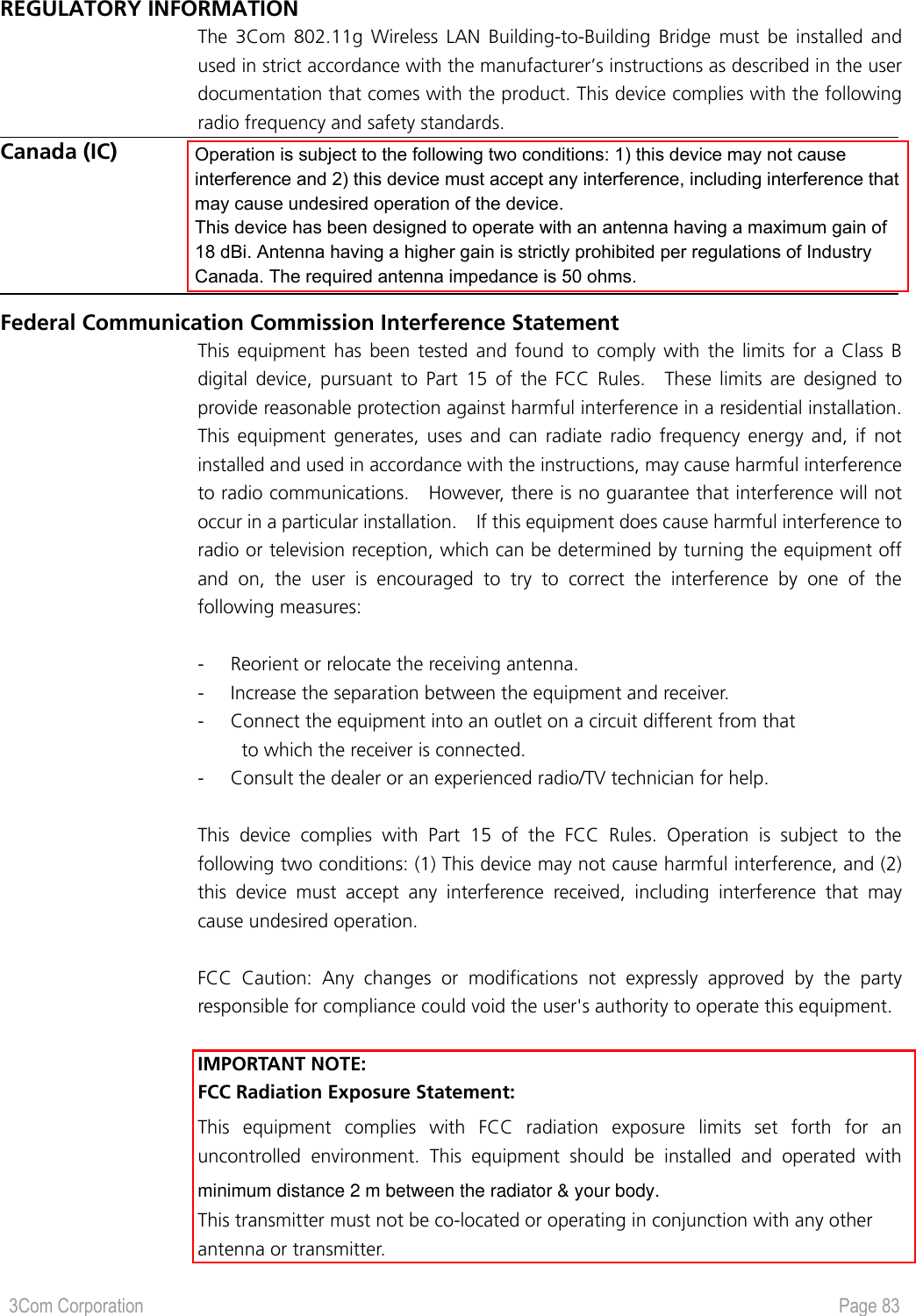
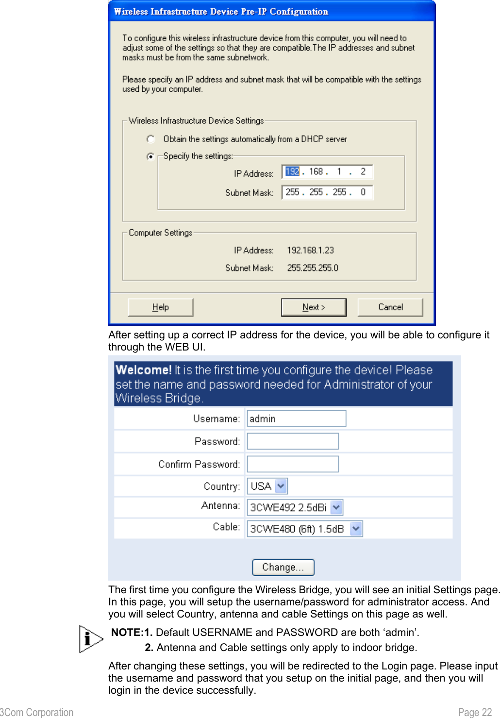
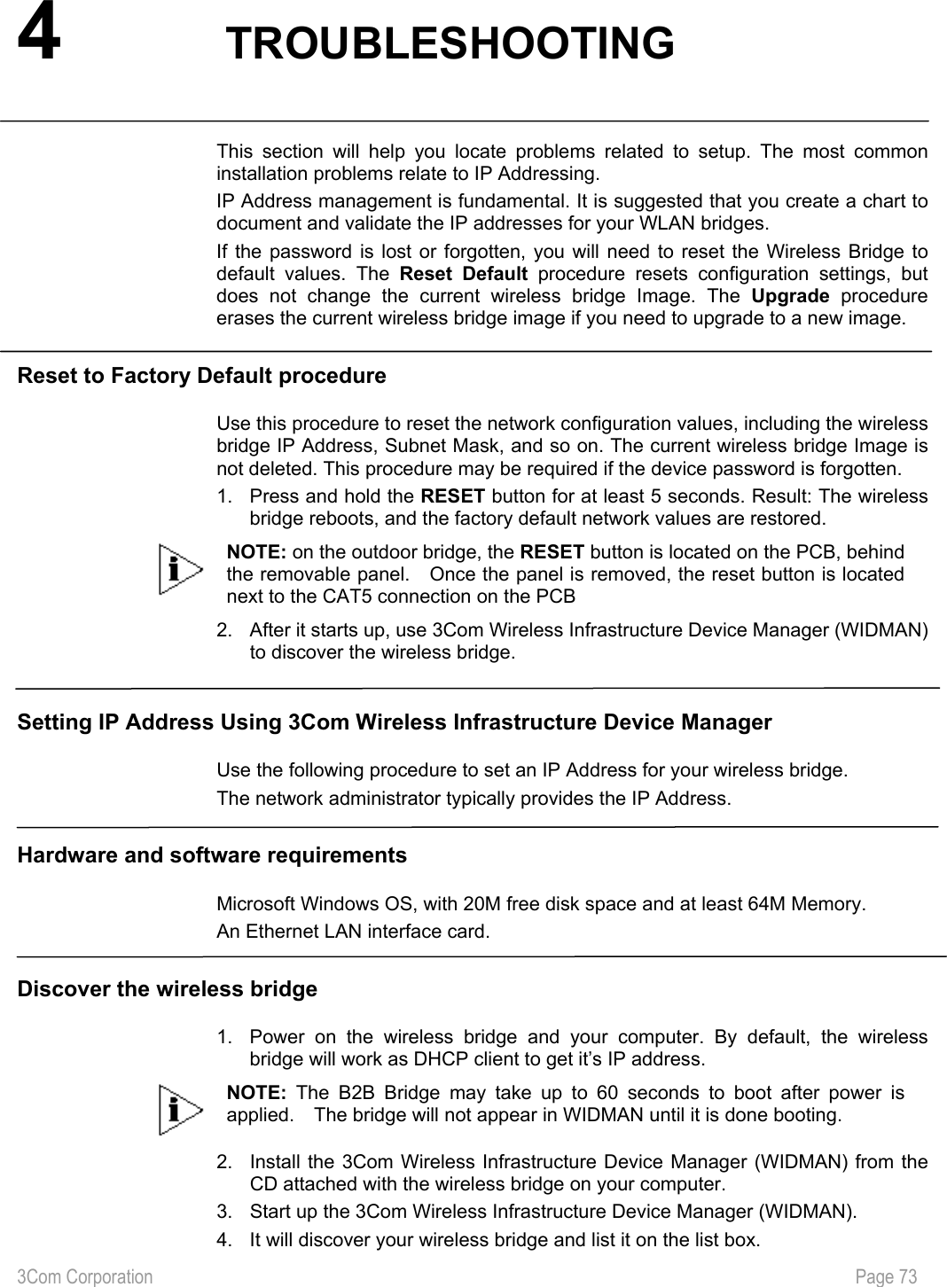
![3Com Corporation Page 21 Find your New Wireless Bridge To find your new Wireless Bridge, open the 3Com Wireless Infrastructure Device Manager (WIDMAN) utility. On start up, the dialog box will look like the Figure below: Click the ‘Refresh’ button and the 3Com Wireless Infrastructure Device Manager (WIDMAN) utility will begin to discover devices. After finding the new Wireless Bridge, it will appear in the list box. Choose the Wireless Bridge in the list box, and then click the ‘Configure…’ button. If 3Com Wireless Infrastructure Device Manager (WIDMAN) finds that your PC cannot connect to the Wireless Bridge by IP, it would pop-up a dialog requesting that you change the IP address of the device. Then the utility will prompt you to enter the password of the bridge. [Note: default password is “blank”] NOTE: It can take up to 60 seconds for the 3Com Building to Building Bridge to boot up after power has been connected. The Bridge will not appear in the WIDMAN utility unit boot up is complete. Click the REFRESH button occasionally until the Bridge appears.](https://usermanual.wiki/Hewlett-Packard-Enterprise/WL565/User-Guide-523544-Page-22.png)
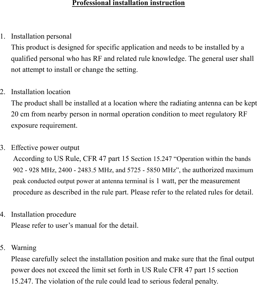
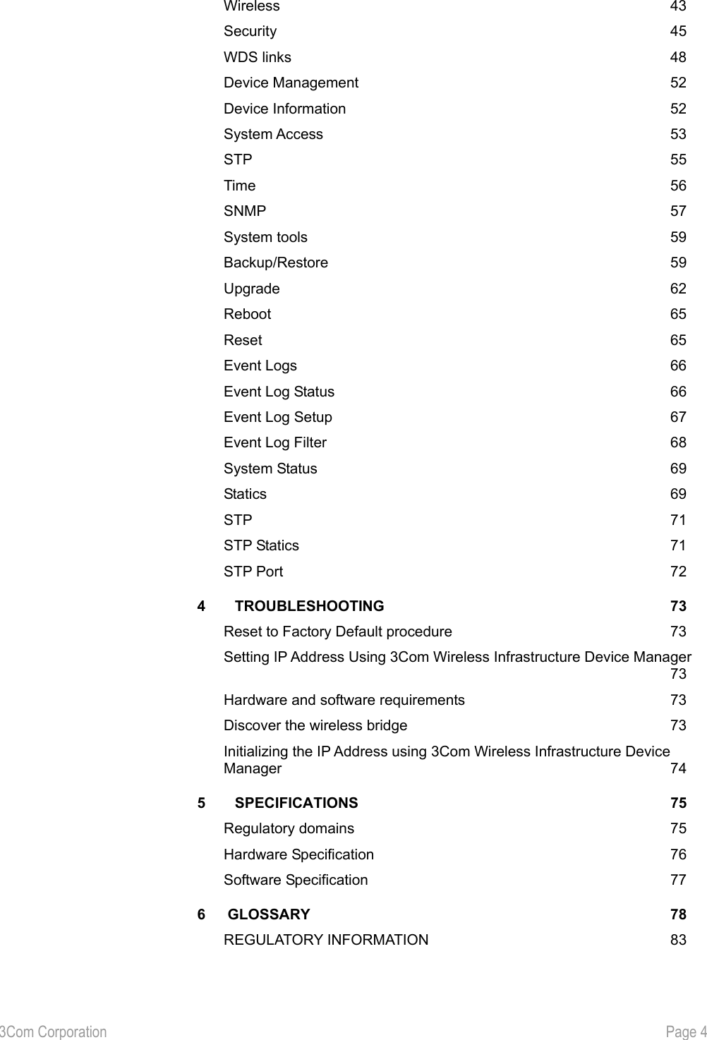
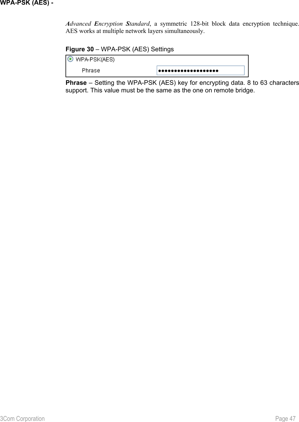
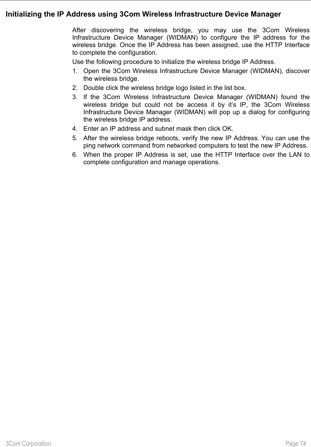
![3Com Corporation Page 33 WEP - To choose WEP encryption, select the Wired Equivalent Privacy (WEP) radio button. You can now choose key length and other Security. Figure 12 – WEP Encryption Settings Key Length – choose the shared Key length from the drop-down menu [64-bits (10 characters)/128-bits (26 characters)]. Key Format –choose the Key Format from the drop-down menu [Hex/ ASCII]. Pre-Shared Key – specify the shared secret. 5 colon-separated HEX (0-9, A-F, and a-f) pairs (e.g. 00:AC:01:35:FF) for the 64-bits WEP encryption; 13 colon-separated HEX (0-9 A-F, and a-f) pairs (e.g. 00:11:22:33:44:55:66:77:88:99:AA:BB:CC) for the 128-bits WEP encryption. To continue the setup wizard click the Next button and the Confirm Settings page will appear. WPA-PSK (TKIP) - If you want to choose TKIP-PSK encryption, select the WPA-PSK (TKIP) radio button in the Security Setup page and click the Next button to configure the TKIP PSK Phrase. Figure 13 – WPA-PSK (TKIP) Settings Phrase – specify WPA-PSK (TKIP) password [8-63 characters] (e.g. aabbccdd). WPA-PSK (AES) - If you want to choose AES-PSK encryption, select the WPA-PSK (AES) radio button in the Security Setup page and click the Next button to configure the AES PSK Phrase. Figure 14 – WPA-PSK (AES) Settings Phrase – specify WPA-PSK (AES) password [8-63 characters] (e.g. aabbccdd).](https://usermanual.wiki/Hewlett-Packard-Enterprise/WL565/User-Guide-523544-Page-34.png)
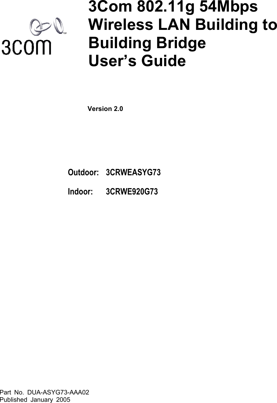
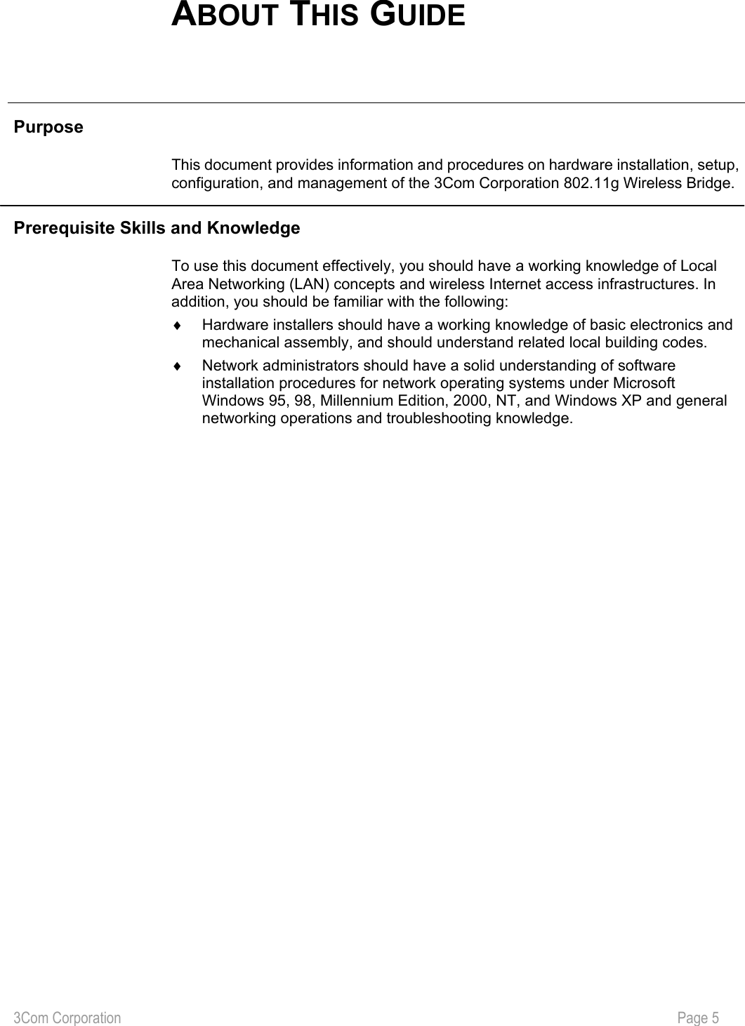
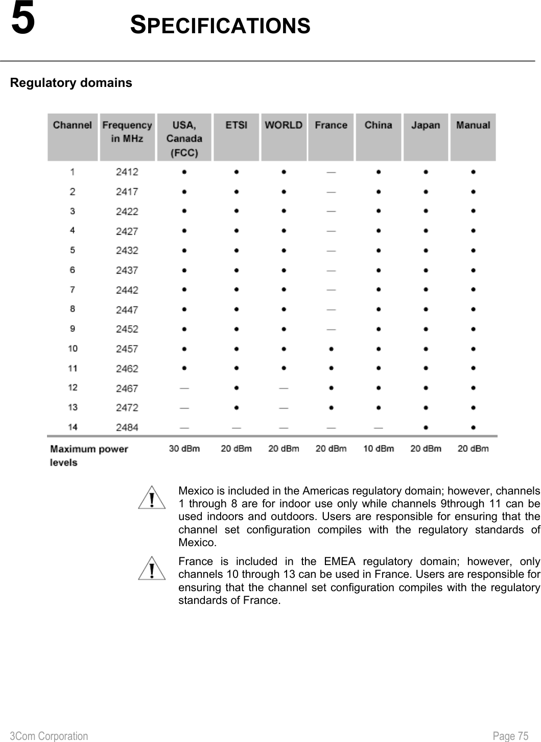
![3Com Corporation Page 36 Device Summary General The General data for the bridge is displayed here. This page has the device information of the bridge, which is shown in the picture below. Figure 17 – General Information Device Name – specify new name value used for user authentication in the system [1-60 characters]. Location Password – specify new password value used for user authentication in the system [1-60 characters]. Contact – specify the name of the person/company responsible for the wireless bridge [1- 60 characters]. 3C number – 3C number of this bridge. It cannot be changed. Firmware version – The version of current firmware. Hardware Version – displays the version number of the software/firmware that controls the bridge (this will be necessary for troubleshooting). Serial Number – The serial number of this bridge.](https://usermanual.wiki/Hewlett-Packard-Enterprise/WL565/User-Guide-523544-Page-37.png)
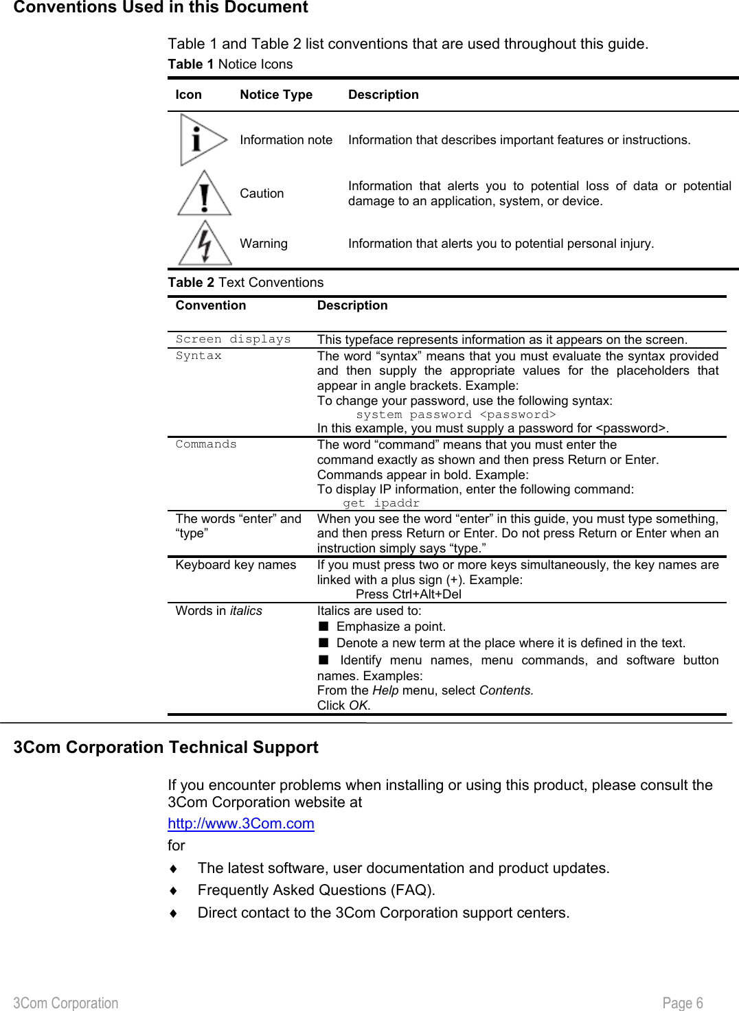
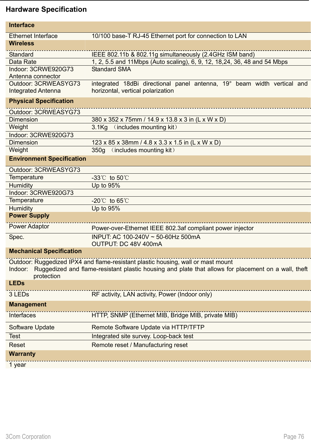
![3Com Corporation Page 38 Wireless The Wireless tab shows the wireless configuration information. Figure 19 – Wireless Information Country – Shows that this bridge is set for the standards of the chosen country. This item is read only. Wireless network name (SSID) – is a unique name for your wireless network [1-32 symbols]. The default SSID is “3Com” but you should change this to a personal wireless network name. The SSID is important to identify bridge to bridge connections when choosing TKIP PSK or AES PSK as the security type. All client bridges must have their client SSID settings configured and must use the same SSID in the same channel. Radio Channel – select the channel that the bridge uses to transmit and receive information. Multiple frequency channels are used to avoid interference between nearby bridges/devices. If you wish to operate more than one bridge in overlapping coverage areas, we recommend a distance of at least four channels between the chosen channels. For example, for three bridges in close proximity choose channels 1, 6 and 11. Broadcast SSID – when selected, your bridge’s SSID is visible in the networks list while scanning the available networks for wireless client. When unselected, the bridge’s SSID is not visible in the available network list. Wireless Output Power – Shows the Maximum output power of this bridge in this domain, read only. Basic Rate Set (Mbps) – select the checkbox to set the Basic data rates at which the station may transmit and receive data. Beacon Period (milliseconds) – this setting specifies the amount of time between beacons in milliseconds. A beacon is a packet broadcast by the bridge to synchronize the wireless network. RTS Threshold (bytes) – specifies the maximum packet size beyond which the Wireless LAN Card invokes its RTS/CTS mechanism. Packets that exceed the](https://usermanual.wiki/Hewlett-Packard-Enterprise/WL565/User-Guide-523544-Page-39.png)
![3Com Corporation Page 39 specified RTS threshold trigger the RTS/CTS mechanism. The NIC transmits packets smaller than this threshold without using RTS/CTS [[0-2347] default: 2347 (2347 means that RTS is disabled)]. Fragmentation Threshold (bytes) – the fragmentation threshold, specified in bytes, determines whether packets will be fragmented and at what size. On an 802.11 wireless LAN, packets exceeding the fragmentation threshold are fragmented, i.e., split into, smaller units suitable for the circuit size. Packets smaller than the specified fragmentation threshold value are not fragmented [[256-2346] default: 2346 (2346 means that fragmentation is disabled)]. Security Security summary displays the general information about wireless security. Figure 20 – Security Information Security Type – Displays which security type this bridge is currently using. Pre-shared Key length– Choose the shared Key length from the drop-down menu [64-bits (10 characters)/128-bits (26 characters)]. Key Format –choose the Key Format from the drop-down menu [Hex/ ASCII].](https://usermanual.wiki/Hewlett-Packard-Enterprise/WL565/User-Guide-523544-Page-40.png)
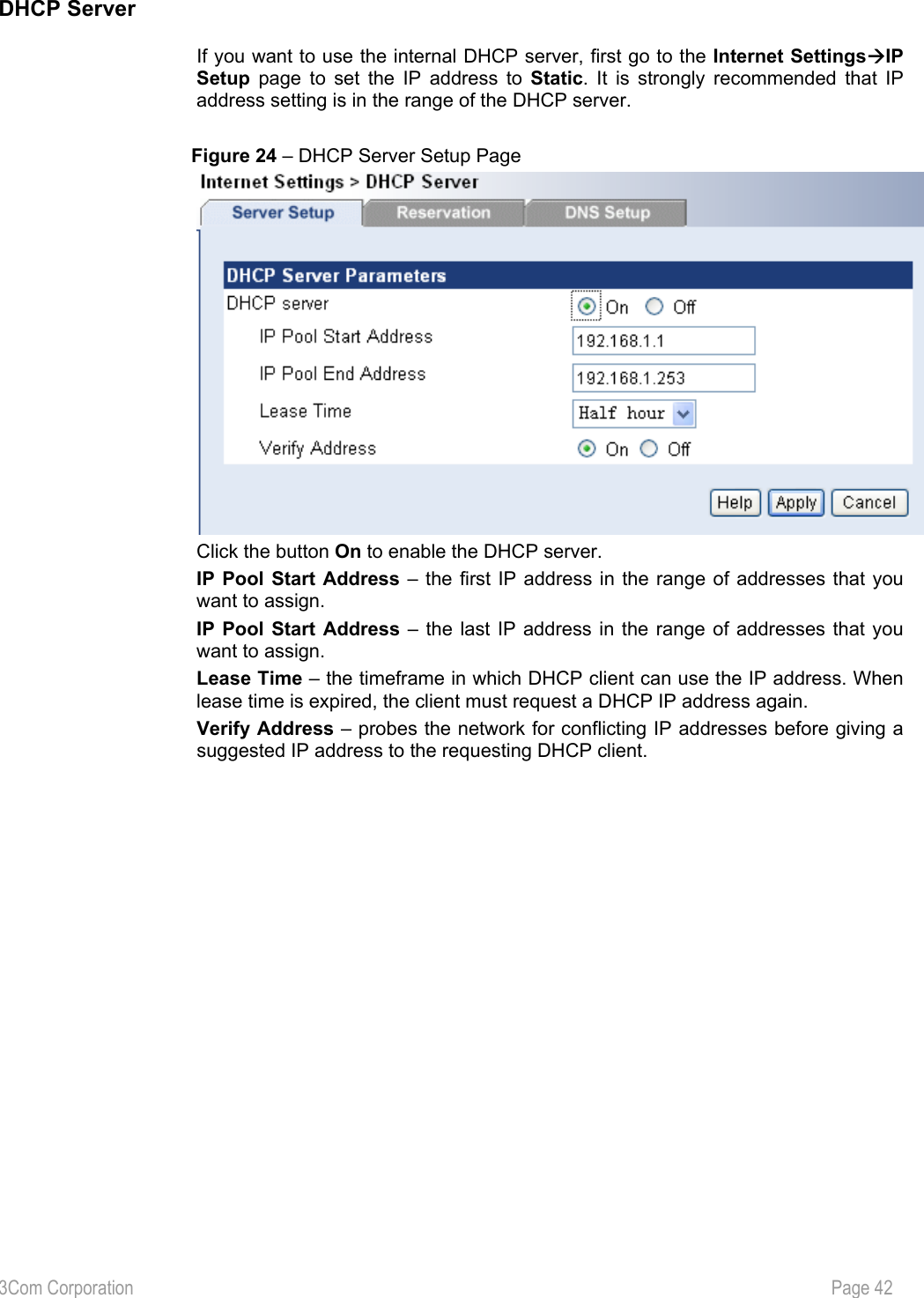
![3Com Corporation Page 41 Internet Settings IP Setup The IP Setup Configuration described below is required for device management. IP addresses can either be retrieved from a DHCP server or configured manually. Figure 22 – IP Settings If the Static IP radio button is selected, the static IP settings are displayed as follow: Figure 23 – Static IP Settings IP Address – specify the bridge’s IP address [digit and dots]. Subnet Mask – specify the bridge’s subnet mask [digit and dots]. Default Gateway – specify the IP address of the bridge’s gateway [digit and dots]. If you change the IP address manually, make sure that the chosen IP address is free and belongs to the same IP subnet as the wired network; otherwise you will lose the connection to the Wireless Bridge from your current PC. If you enable the DHCP client via a Web browser, the browser will loose the connection after rebooting, because the IP address assigned by the DHCP server is not predictable. The Wireless Bridge can be set as a DHCP server. Use DHCP configuration to provide dynamic client IP Address from a range of IP Address.](https://usermanual.wiki/Hewlett-Packard-Enterprise/WL565/User-Guide-523544-Page-42.png)
![3Com Corporation Page 43 Wireless Settings Wireless The Wireless Setup consists of two pages: Radio and Advanced. Radio part shows the basic settings of radio channel, and Advanced page shows the advanced information. (e.g. Beacon Interval is 100) Figure 25 – Wireless Setup Radio Country – Shows this bridge is set to the regulatory requirements of that country. This item is read only. [North American version of the Bridge only has settings for FCC conformity] Regulatory domain – This is the organization that certifies the Wireless Bridge for use in your country. It determines which radio channels can be used to transmit and receive signals. This is a factory setting and cannot be changed. Wireless network name (SSID) – is a unique name for your wireless network [1-32 characters]. The default SSID is “3Com” you should change this to a personal wireless network name. The SSID is important to identify bridge to bridge connections when choosing TKIP PSK or AES PSK as the security type. All client bridges must have their client SSID settings configured and must use the same SSID in the same channel. Radio Channel – select the channel that the bridge uses to transmit and receive information. Multiple frequency channels are used to avoid interference between nearby bridges/devices. If you wish to operate more than one bridge in overlapping coverage areas, we recommend a distance of at least four channels between the chosen channels. For example, for three bridges in close proximity choose channels 1, 6 and 11. 17](https://usermanual.wiki/Hewlett-Packard-Enterprise/WL565/User-Guide-523544-Page-44.png)
![3Com Corporation Page 44 Before changing radio settings manually, verify that these settings comply with government regulations. At all times, it is the responsibility of the end-user to ensure that the installation complies with local radio regulations. Refer to the appendix, Regulatory Domain section. Broadcast SSID – when selected, your bridge’s SSID is visible in the networks list while scanning the available networks for wireless client. When unselected, the bridge’s SSID is not visible in the available network list. Domain Max Output Power – Shows the maximum output power of this bridge in this domain, read only. Cancel – restore all previous values. Apply – save changed configuration. Figure 26 – Wireless Setup Advanced Basic Rate Set (Mbps) – select the checkbox to set the Basic data rates at which the station may transmit and receive data. Beacon Period (milliseconds) – this setting specifies the amount of time between beacons in milliseconds. A beacon is a packet broadcast by the bridge to synchronize the wireless network. DTIM Period (count) – this attribute specifies the number of beacon intervals that elapse between transmissions of Beacon frames containing a TIM element whose DTIM Count field is 0. This value is transmitted in the DTIM Period field of Beacon frames. RTS Threshold (bytes) – defines the maximum packet size beyond which the Wireless Bridge invokes its RTS/CTS mechanism. Packets that exceed the specified RTS threshold trigger the RTS/CTS mechanism. The NIC transmits packets smaller than this threshold without using RTS/CTS [[0-2347] default: 2347 (2347 means that RTS is disabled)].](https://usermanual.wiki/Hewlett-Packard-Enterprise/WL565/User-Guide-523544-Page-45.png)
![3Com Corporation Page 45 Fragmentation Threshold (bytes) – the fragmentation threshold, identifies in bytes, whether packets will be fragmented and at what size. On an 802.11 wireless LAN, packets exceeding the fragmentation threshold are fragmented, i.e., split into, smaller units suitable for the circuit size. Packets smaller than the specified fragmentation threshold value are not fragmented [[256-2346] default: 2346 (2346 means that fragmentation is disabled)]. Cancel – restore all previous values. Apply – save changed configuration. Security The Wireless Security Settings Page shows the summary of wireless security settings, which includes Wired Equivalent Privacy (WEP), WPA-PSK (TKIP) and WPA-PSK (AES). Click each for details. Figure 27 – Wireless Security Settings Cancel – restore all previous values. Apply – save changed configuration.](https://usermanual.wiki/Hewlett-Packard-Enterprise/WL565/User-Guide-523544-Page-46.png)
![3Com Corporation Page 46 WEP - WEP is a data privacy mechanism based on a 64-bit or 128-bit shared key algorithm as described in the IEEE 802.11 standard. Static WEP uses a symmetric scheme where the same key and algorithm are used for both encryption and decryption of data. The radio button Use WEP Encryption defines if encryption will be used or not. To enable WEP encryption, select this radio button. Figure 28 – Wired Equivalent Privacy (WEP) Settings Enter the encryption key to be used to encrypt and decrypt wireless traffic: 64-bits – specify pre-shared key as 10 Hex characters or 5 ASCII bytes. 128-bits – specify pre-shared key as 26 Hex characters or 13 ASCII bytes. Key Format –choose the Key Format from the drop-down menu [Hex/ ASCII]. Pre-shared Key – Setting the WEP key for encrypting data. 64bits and 128bits encryption are supported. This value must be the same as on the host/local and remote bridge(s). WPA-PSK (TKIP) - The Temporal Key Integrity Protocol (TKIP), pronounced “tee-kip”, is part of the IEEE 802.11i encryption standard for wireless LANs. TKIP is the next generation of WEP, the Wired Equivalency Protocol, which is used to secure 802.11 wireless LANs. TKIP provides per-packet key mixing, a message integrity check and a re-keying mechanism, thus fixing the flaws of WEP. Figure 29 – WPA-PSK (TKIP) Settings Phrase – Setting the WPA-PSK (TKIP) key for encrypting data. 8 to 63 characters support. This value must be the same as the one on remote bridge.](https://usermanual.wiki/Hewlett-Packard-Enterprise/WL565/User-Guide-523544-Page-47.png)
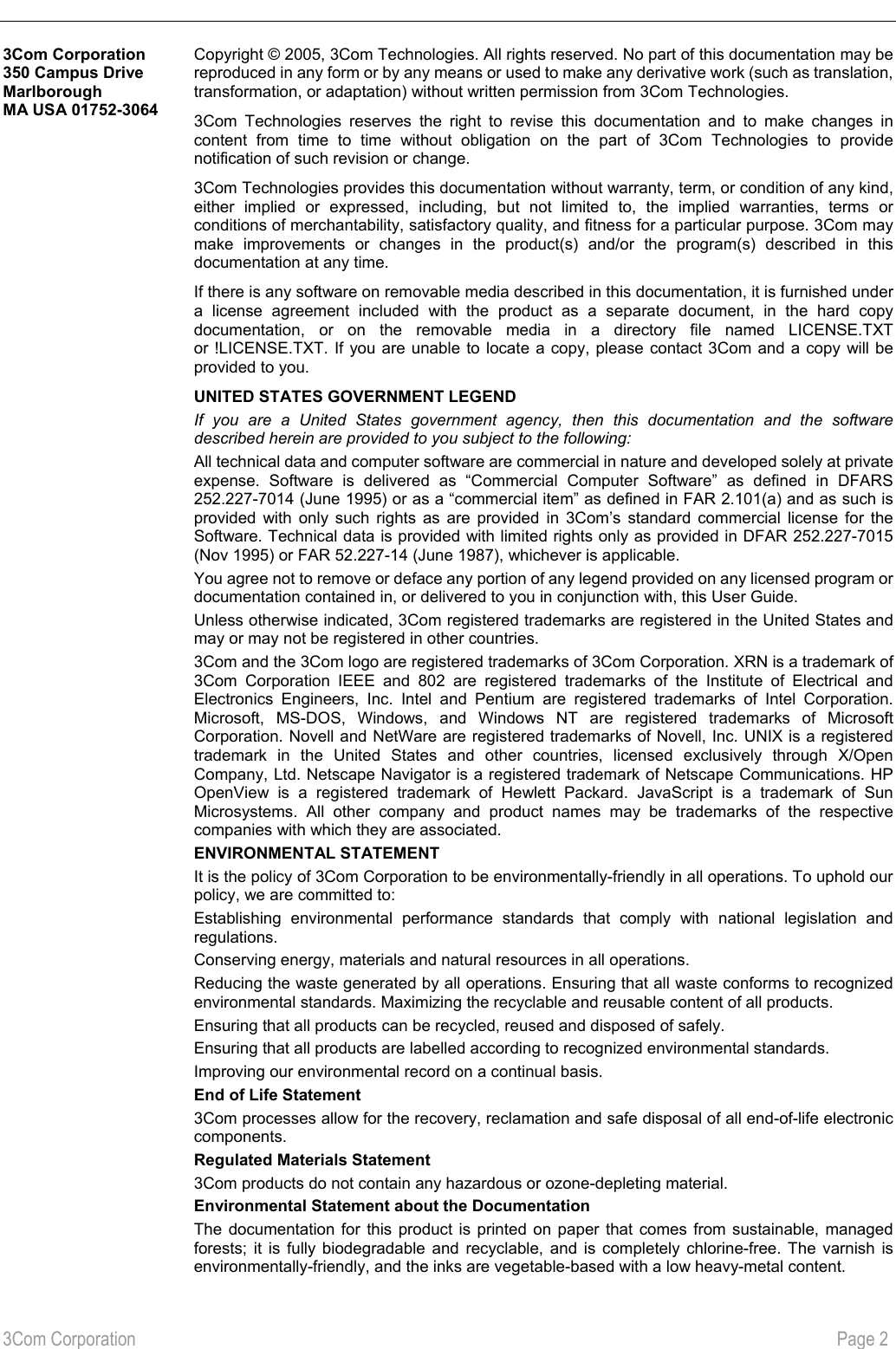
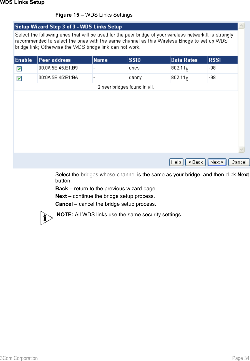
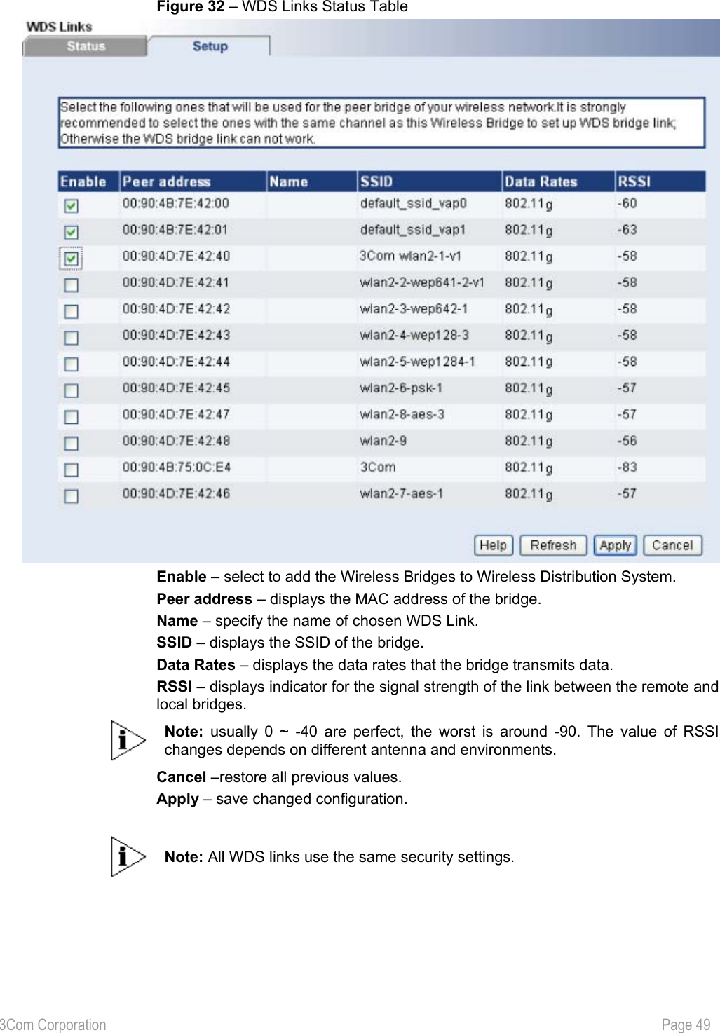
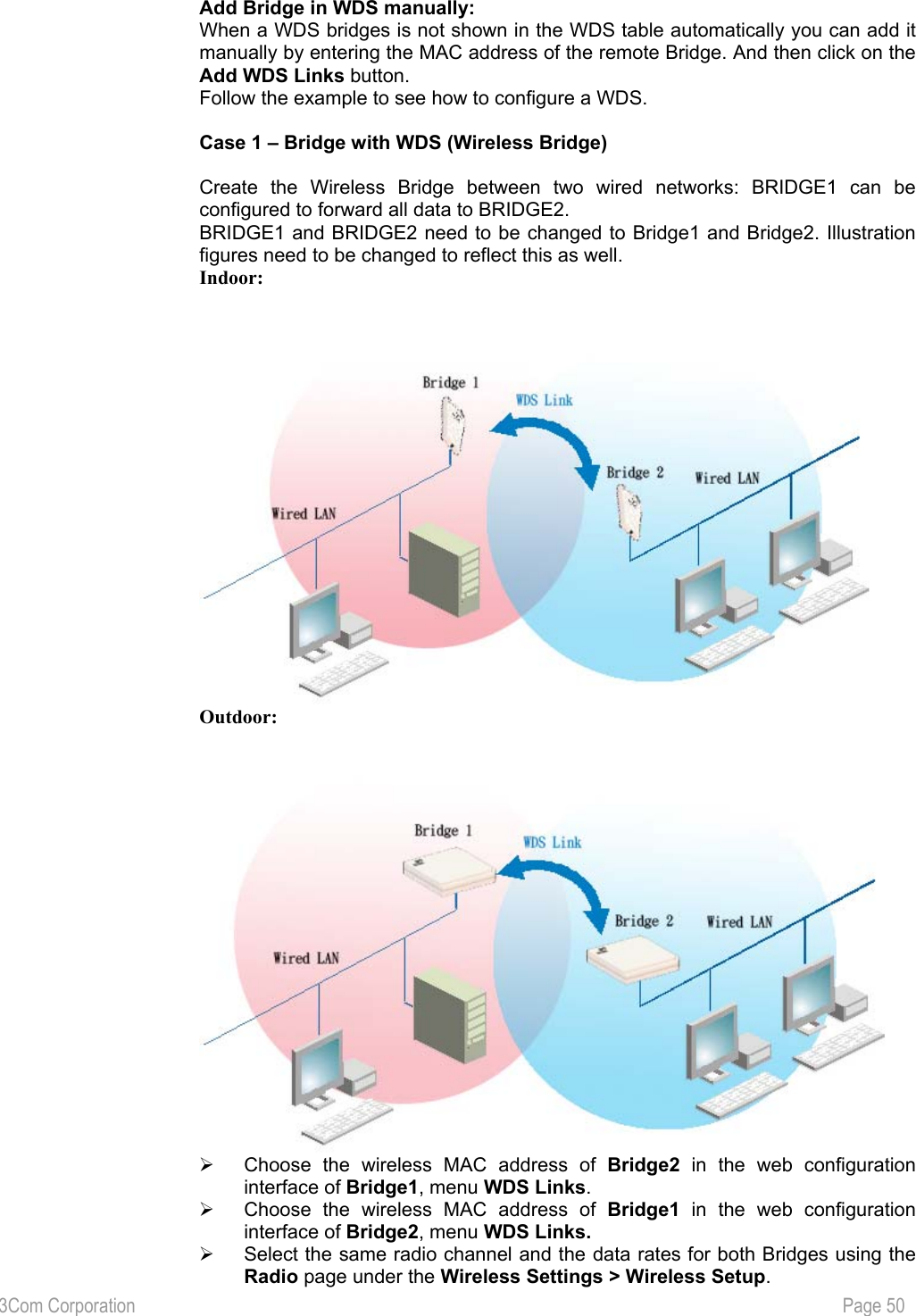
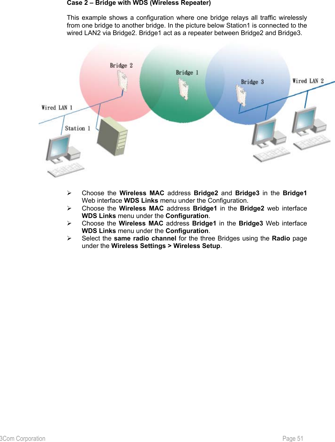
![3Com Corporation Page 48 WDS links The Wireless Bridge supports WDS (Wireless Distribution System) to act as bridges or repeaters. Choose the WDS Links menu if you want to setup bridge links between different bridges. The figure below shows all the bridges status: Figure 31 – WDS Links Status Table Peer address – displays the MAC address of the bridge. Name – specify the name of chosen WDS Link. SSID – is a unique name for your wireless network [1-32 characters]. The default SSID is “3Com” you should change this to a personal wireless network name. The SSID is important to identify bridge to bridge connections when choosing TKIP PSK or AES PSK as the security type. All client bridges must have their client SSID settings configured and must use the same SSID in the same channel. Data Rates – displays the data rates that the bridge transmits data. RSSI – displays indicator for the signal strength of the link between the remote and local bridges. Cancel –restore all previous values. Apply – save changed configuration. The WDS mode is configured by selecting the WDS link peer bridges MAC address in each other’s bridge configuration e.g. Web interface. The radio channel and the operational rates in all WDS link peer bridges must be the same. Bridges participating in a WDS network DO NOT have to be configured with the same SSID. On the Wireless Bridge you can add desired bridges in to WDS (wireless distribution system) in two ways: by selecting bridges from the table or you can add them manually. Add bridge in WDS from the WDS Links table: ♦ Access the WDS Links Table by clicking on the WDS Links menu. This table shows information for wireless networks in a local geographic area. On this table an administrator can see WDS Links, their operating channels, data rates, RSSI and the Age. ♦ Select the checkbox on the Enabled column on chosen WDS link’s row to add this device in the Wireless Distribution System. The checkboxes will be active only of those WDS links that use the same channel as your device:](https://usermanual.wiki/Hewlett-Packard-Enterprise/WL565/User-Guide-523544-Page-49.png)
![3Com Corporation Page 52 Device Management Device Information You can use the Device Information to identify the bridge for yourself and other information of these devices which is shown in the picture below. Figure 33 – The device information of this bridge. Device Name – specify new name value used for user authentication in the system [1-60 characters]. Location Password – specify new password value used for user authentication in the system [1-60 characters]. Contact – specify the name of the person/company responsible for the wireless bridge [1- 60 characters]. Confirm Password – re-enter the new password to verify its accuracy. Apply– Apply administrator’s password.](https://usermanual.wiki/Hewlett-Packard-Enterprise/WL565/User-Guide-523544-Page-53.png)
![3Com Corporation Page 53 System Access Use the Systems Access menu to change the name and password of the Administrator and User for any further configuration changes. Figure 34 – Change Administrator’s Name and Password Name – specify new name value used for user authentication in the system [3-16 characters]. New Password – specify new password value used for user authentication in the system [3-16 characters]. Confirm Password – re-enter the new password to verify its accuracy. Apply– Apply administrator’s password.](https://usermanual.wiki/Hewlett-Packard-Enterprise/WL565/User-Guide-523544-Page-54.png)
![3Com Corporation Page 54 Figure 35 – Change User’s Name and Password Name – specify new name value used for user authentication in the system [3-16 characters]. New Password – specify new password value used for user authentication in the system [3-16 characters]. Confirm Password – re-enter the new password to verify its accuracy. Apply– Apply administrator’s password. Keep in mind that the Reset button will set the username and password back to default.](https://usermanual.wiki/Hewlett-Packard-Enterprise/WL565/User-Guide-523544-Page-55.png)
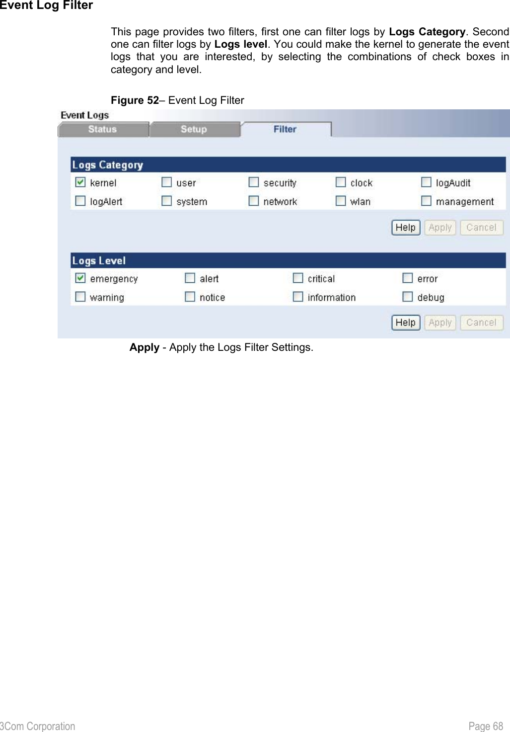
![3Com Corporation Page 66 Event Logs Event Log Status The event log system informs about internal services and provides debug messages in case of malfunctions or network problems. The trace system can help operators to locate miss configurations and system errors. Use the Event Log menu to view current Syslog messages in case of troubleshooting of one of the services: Figure 50– Event Log Status Clear – delete all displayed logged messages. Level – shows how important the event (or how critical the error) is [Emergency/Alert/Critical/Error/Warning/Notice/Info/Debug]. Facility – indicates the unique identifier of the facility that generated the event. A facility can be a hardware device, a protocol, or a module of the system software. [Kernel/User/Security/Clock/LogAudit/LogAlert/System/Network/Wlan/management] ID – indicates an internal number for the event. Description – indicates description of the event. Count – indicates the number of times this event has occurred. Time – indicates time when this event has occurred, in months, days and hours: minutes: seconds since the bridge was started.](https://usermanual.wiki/Hewlett-Packard-Enterprise/WL565/User-Guide-523544-Page-67.png)
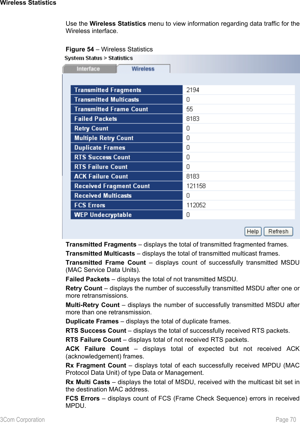
![3Com Corporation Page 69 System Status Statics Interface Statistics Use the Interface Statistics menu for a summary of interface statistics. Figure 53 – Interface Statistics Interface – indicates a unique name for each interface. Status – shows the current operational state of the interface [up/down]. InOctets – indicates the amount of received bytes on the interface, including framing characters. InUcast – totals unicast frames received at the port excluding discards. InMcast – totals multicast frames received at the port excluding discards. OutOctets – shows the total transmitted frames of the interface in bytes, including framing characters. OutUcast – totals unicast frames transmitted from the port including discards. OutMcast – totals multicast frames transmitted from the port including discards. Refresh – Refresh local page and all the statistics.](https://usermanual.wiki/Hewlett-Packard-Enterprise/WL565/User-Guide-523544-Page-70.png)
![3Com Corporation Page 78 6 GLOSSARY Symbols: 802.11: 802.11 is a family of specifications for wireless local area networks (WLANs) developed by a working group of the Institute of Electrical and Electronics Engineers (IEEE). The original specification provides for an Ethernet Media Access Controller (MAC) and several physical layer (PHY) options, the most popular of which uses GFSK modulation at 2.4GHz, enabling data rates of 1 or 2Mbps. Since its inception, two major PHY enhancements have been adopted and become "industry standards". 802.11b adds CCK modulation enabling data rates of up to 11Mbps, and 802.11a specifies OFDM modulation in frequency bands in the 5 to 6GHz range, and enables data rates up to 54Mbps. A AAA: Authentication, Authorization and Accounting. A method for transmitting roaming access requests in the form of user credentials (typically user@domain and password), service authorization, and session accounting details between devices and networks in a real-time manner. AES: Advanced Encryption Standard, a symmetric 128-bit block data encryption technique. AES works at multiple network layers simultaneously. authentication: The process of establishing the identity of another unit (client, user, device) prior to exchanging sensitive information. B backbone: The primary connectivity mechanism of a hierarchical distributed system. All systems, which have connectivity to an intermediate system on the backbone, are assured of connectivity to each other. This does not prevent systems from setting up private arrangements with each other to bypass the backbone for reasons of cost, performance, or security. Bandwidth: Technically, the difference, in Hertz (Hz), between the highest and lowest frequencies of a transmission channel. However, as typically used, the amount of data that can be sent through a given communication circuit. For example, typical Ethernet has a bandwidth of 100Mbps. bps: bits per second. A measure of the data transmission rate. D DHCP: Dynamic Host Configuration Protocol (DHCP) is a communications protocol that lets network administrators manage centrally and automate the assignment of Internet Protocol (IP) addresses in an organization's network. Using the Internet Protocol, each machine that can connect to the Internet needs a unique IP address. When an organization sets up its computer users with a connection to the Internet, an IP address must be assigned to each machine. Without DHCP, the IP address must be entered manually at each computer and, if computers move to another location in another part of the network, a new IP address must be entered. DHCP lets a network administrator supervise and distribute IP addresses from a central point and automatically sends a new IP address when a computer is plugged into a different place in the network. DNS: Domain Name Service. An Internet service that translates a domain name such as 3Com Corporation to an IP address, in the form xx.xx.xx.xx, where xx is an 8 bit hex number. E EAP: Extensible Authentication Protocol. Defined in [RFC2284] and used by IEEE 802.1x Port Based Authentication Protocol [8021x] that provides additional authentication methods. EAP-TLS (Transport Level Security) provides for mutual authentication, integrity-protected ciphersuite negotiation and key exchange between two endpoints [RFC2716]. EAP-TTLS (Tunneled TLS Authentication Protocol) provides an authentication negotiation enhancement to TLS (see Internet-Draft <draft-ietf-pppext-eap-ttls-00.txt>).](https://usermanual.wiki/Hewlett-Packard-Enterprise/WL565/User-Guide-523544-Page-79.png)