Hewlett Packard Enterprise WL605 3Com® AirConnect 9550 11n 2.4 + 5GHz PoE Access Point User Manual WP741AP
Hewlett-Packard Company 3Com® AirConnect 9550 11n 2.4 + 5GHz PoE Access Point WP741AP
UserManual.wiki
>
Hewlett Packard Enterprise
>
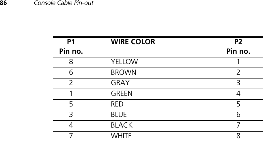
WL605 User Manual
User Manual
Navigation menu
Upload a User Manual
Namespaces
Wiki Guide
HTML
PDF
Info
Views
User Manual
Discussion / Help
Navigation

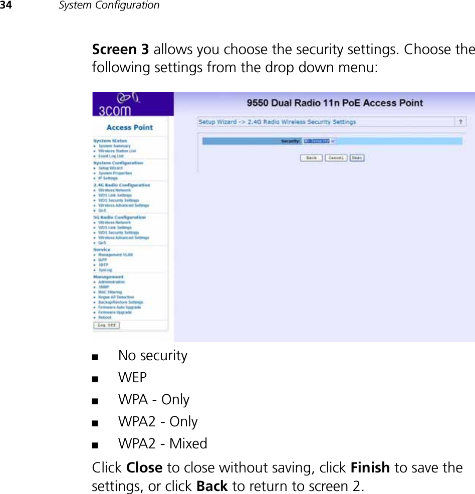
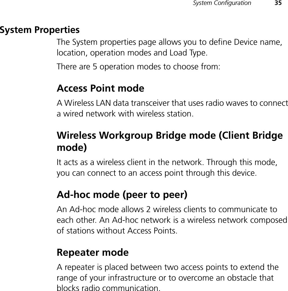
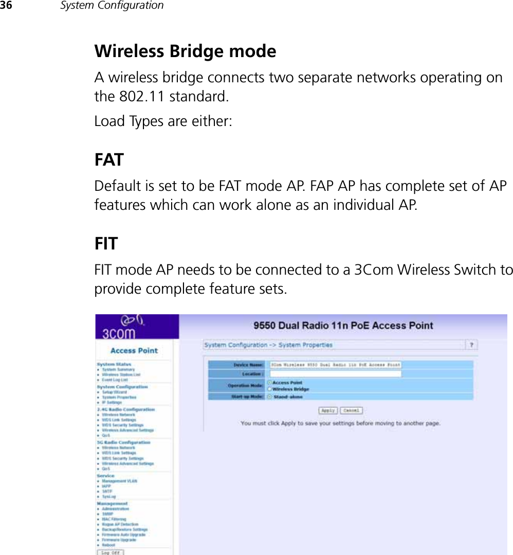
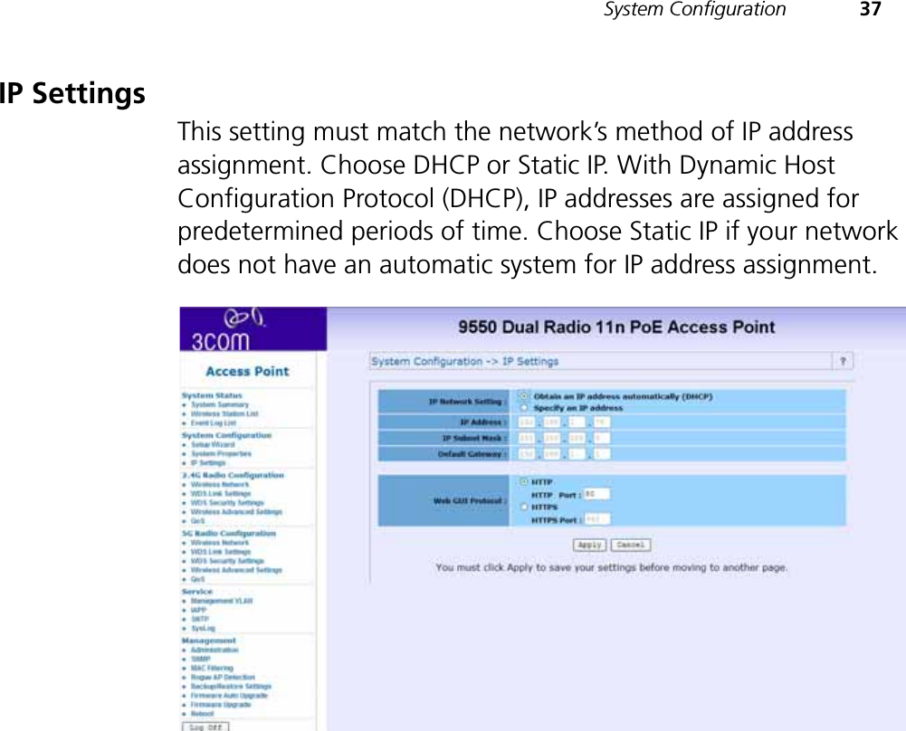
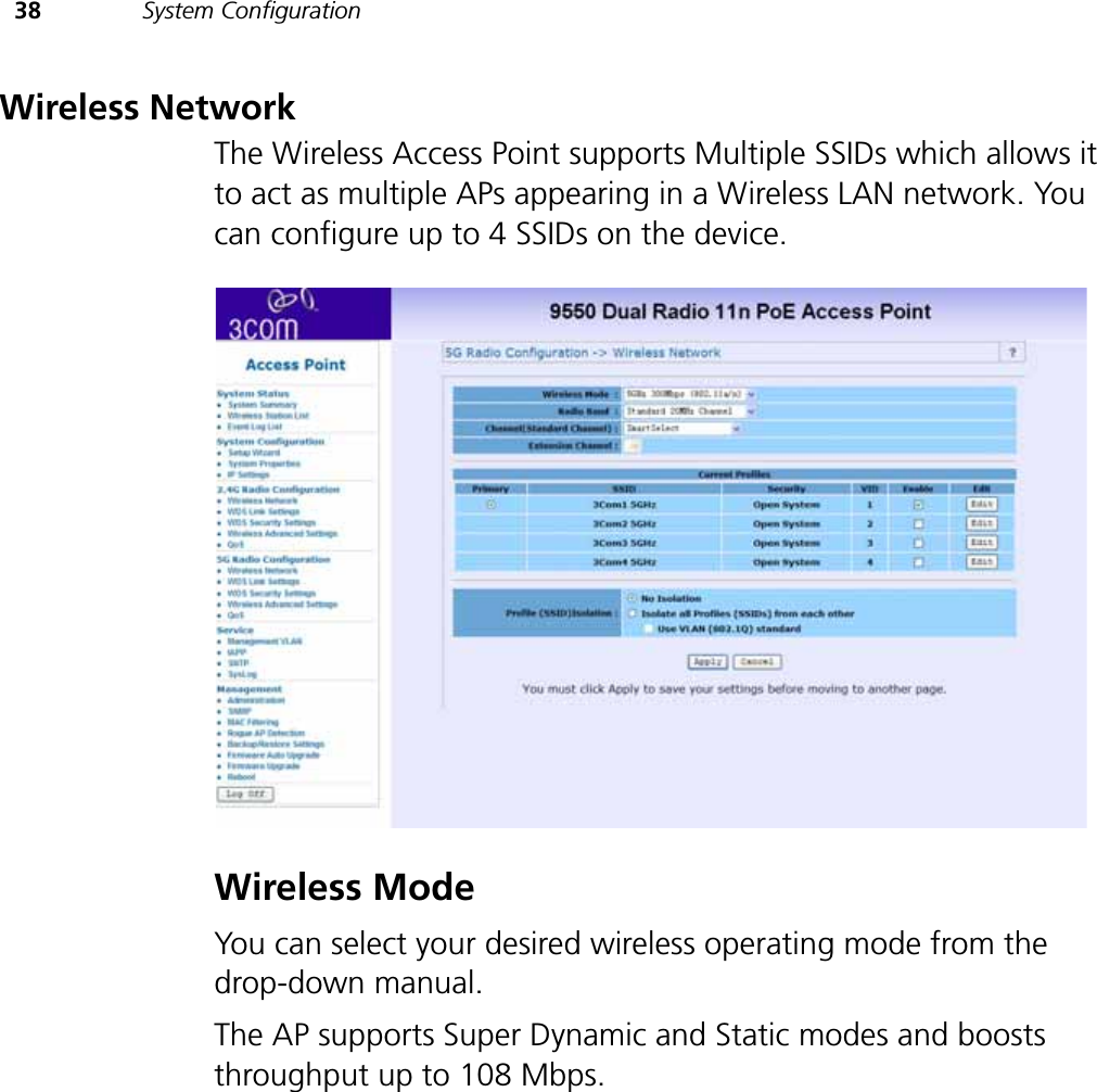
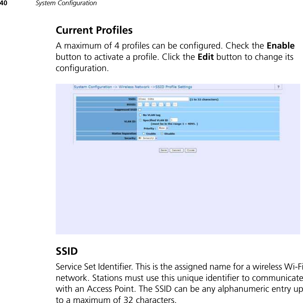
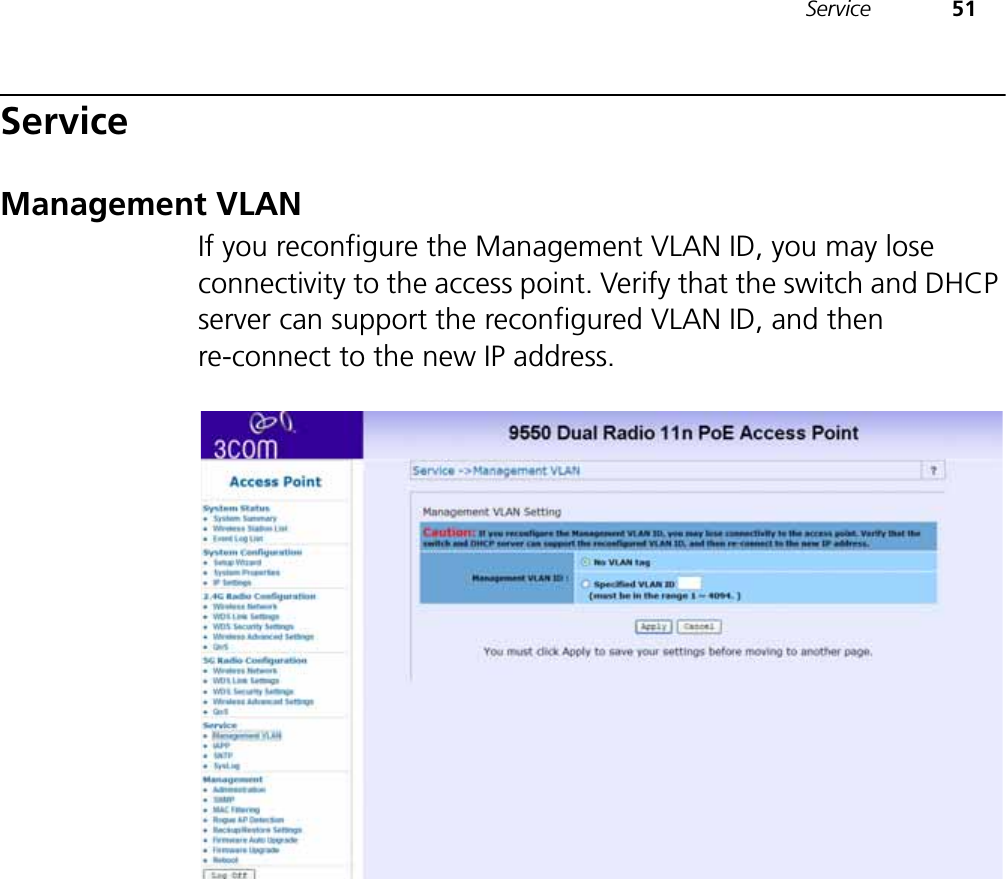
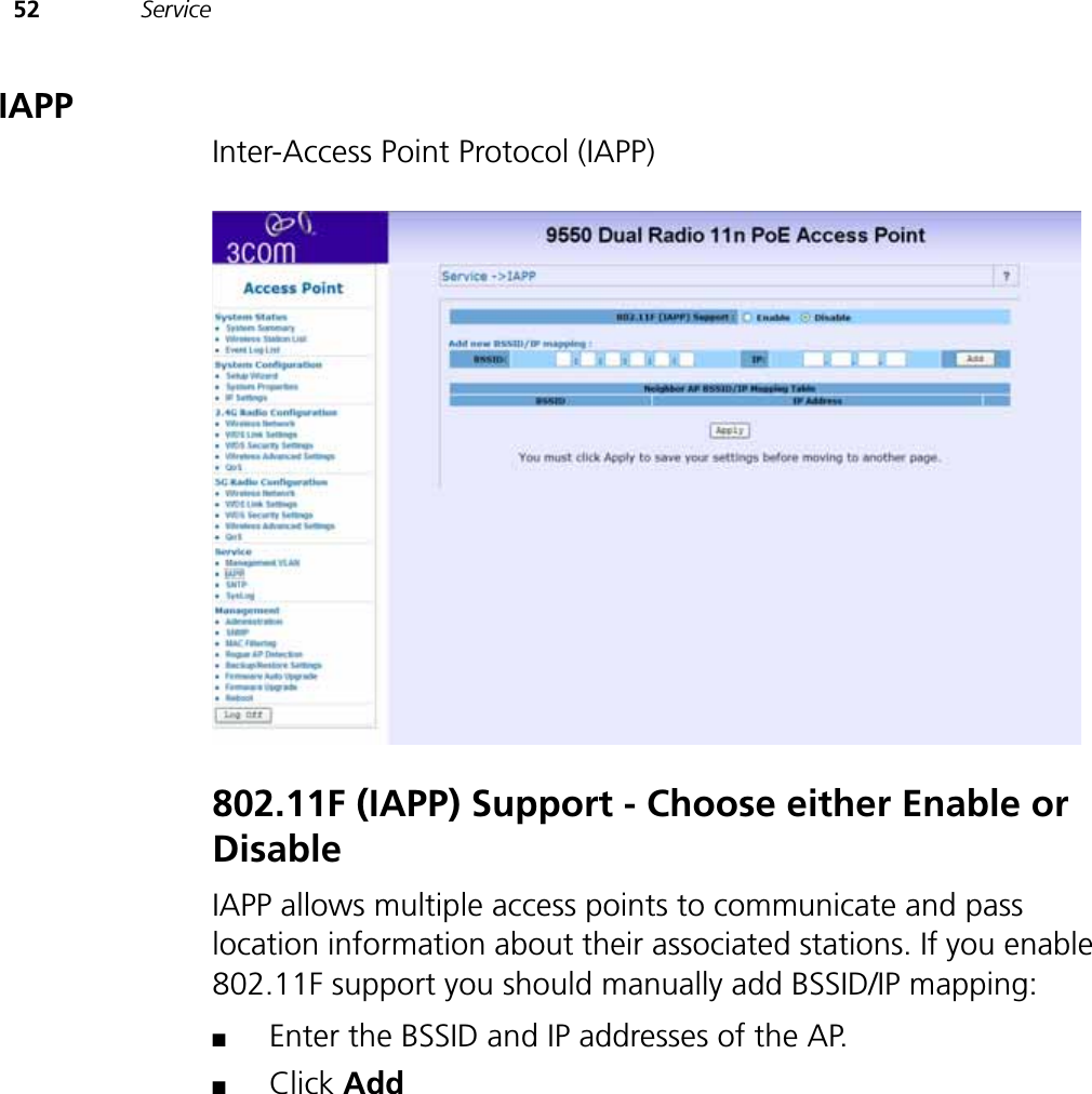
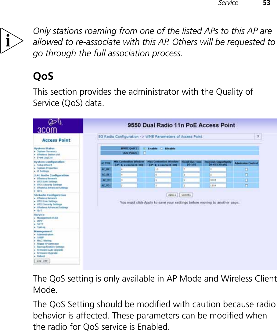
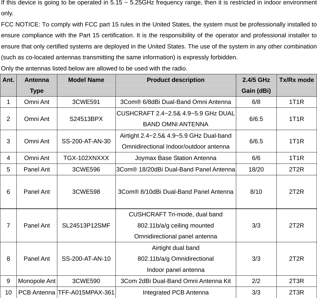
![Federal Communication Commission Interference Statement This equipment has been tested and found to comply with the limits for a Class B digital device, pursuant to Part 15 of the FCC Rules. These limits are designed to provide reasonable protection against harmful interference in a residential installation. This equipment generates, uses and can radiate radio frequency energy and, if not installed and used in accordance with the instructions, may cause harmful interference to radio communications. However, there is no guarantee that interference will not occur in a particular installation. If this equipment does cause harmful interference to radio or television reception, which can be determined by turning the equipment off and on, the user is encouraged to try to correct the interference by one of the following measures: z Reorient or relocate the receiving antenna. z Increase the separation between the equipment and receiver. z Connect the equipment into an outlet on a circuit different from that to which the receiver is connected. z Consult the dealer or an experienced radio/TV technician for help. This device complies with Part 15 of the FCC Rules. Operation is subject to the following two conditions: (1) This device may not cause harmful interference, and (2) this device must accept any interference received, including interference that may cause undesired operation. FCC Caution: Any changes or modifications not expressly approved by the party responsible for compliance could void the user's authority to operate this equipment. This device and its antenna(s) must not be co-located or operating in conjunction with any other antenna or transmitter. IMPORTANT NOTE: FCC Radiation Exposure Statement: This equipment complies with FCC / IC RSS-102 radiation exposure limits set forth for an uncontrolled environment. This equipment should be installed and operated with minimum distance 20cm between the radiator & your body. Canada C Request "Operation is subject to the following two conditions: (1) this device may not cause interference, and (2) this device must accept any interference, including interference that may cause undesired operation of the device." "To reduce potential radio interference to other users, the antenna type and its gain should be so chosen that the equivalent isotropically radiated power (EIRP) is not more than that required for successful communication" "This device has been designed to operate with an antenna having a maximum gain of 18 dBi. Antenna having a higher gain is strictly prohibited per regulations of Industry Canada. The required antenna impedance is 50 ohms." “To reduce potential radio interference to other users, the antenna type and its gain should be so chosen that the equivalent isotropically radiated power (e.i.r.p.) is not more than that permitted for successful communication.” The County Code Selection feature is disabled for products marketed in the US/Canada This Class [B] digital apparatus complies with Canadian ICES-003. Cet appareil numérique de la classe [B] est conforme à la norme NMB-003 du Canada.](https://usermanual.wiki/Hewlett-Packard-Enterprise/WL605/User-Guide-958354-Page-94.png)